

MAKELSAN BOXER BX3310, BOXER BX3330, BOXER BX3315, BOXER BX3320, BOXER BX3340 User Manual
...
USER MANUAL
BOXER SERIES
10 - 20 KVA

USER MANUAL
BOXER SERIES
10 - 20 KVA
AG–SD-109
Rev:0
AG-SD-109 Publishing Date: 13.10.2015 Revision No: 0 Rev. Date:
About The Manual
This manual is prepared for the users of Boxer 10-20 kVA.
Companion Manuals
For further information about this device and its options, please visit www.makelsan.com.tr
Updates
Please visit www.makelsan.com.tr for updates. Always use the latest manuals.
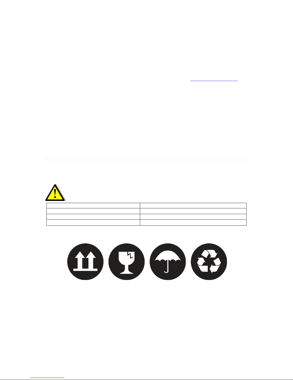
Shipment
Carrying vehicles or handling accessories must have enough features and characteristics to carry
UPS’s weight.
DO NOT LIFT HEAVY DUTY WEIGHT WITHOUT HELP
1 Person
<18 kg (<40 lb)
2 People
18-32 kg (40-70 lb)
3 People
32-55 kg (70-120 lb)
Carrying vehicles or handling accessories
>55 kg (>120 lb)
Be more careful of sudden movements, especially when batteries are inside of cabinet.

BOXER SERIES 10-20 KVA CONTENTS
AG-SD-109 Publishing Date: 13.10.2015 Revision No: 0 Rev. Date:
CONTENTS
1 SAFETY and WARNINGS ......................................................................................................................................... 1
1.1 Warnings .................................................................................................................................................................... 1
1.2 Clearance and Access ............................................................................................................................................ 2
1.3 Storage ........................................................................................................................................................................ 2
1.4 Shipment .................................................................................................................................................................... 2
2 PRODUCT DESCRIPTION ............................................................................................................................................. 4
2.1 General Information .............................................................................................................................................. 9
2.1.1 Static Transfer Switch .................................................................................................................................. 9
2.1.2 Battery Temperature Regulation .......................................................................................................... 10
2.2 UPS’s Operation Modes ..................................................................................................................................... 10
2.2.1 Normal (Online) Mode .............................................................................................................................. 10
2.2.2 Battery (Stored) Mode .............................................................................................................................. 10
2.2.3 Bypass Mode ................................................................................................................................................. 10
2.2.4 Automatic Restart Mode ........................................................................................................................... 11
2.2.5 Maintenance Mode ..................................................................................................................................... 11
2.3 Battery Management ......................................................................................................................................... 11
2.3.1 Advanced Level Functions (Automatic Battery Test) .................................................................. 12
2.4 User Panel ............................................................................................................................................................... 13
2.4.1 Opening Screen ............................................................................................................................................ 15
2.4.2 Main Menu ...................................................................................................................................................... 15
2.4.3 Navigating Through the Menus ............................................................................................................. 15
2.4.4 Password Protected Menus .................................................................................................................... 16
2.4.5 Control Menu ................................................................................................................................................ 16
2.4.6 Status Menu ................................................................................................................................................... 16
2.4.7 Setup Menu .................................................................................................................................................... 17
2.4.8 Logging Menu ................................................................................................................................................ 20
3 INSTALLATION ............................................................................................................................................................. 21
3.1 Single Module Installation ............................................................................................................................... 21
3.1.1 Warnings ......................................................................................................................................................... 21
3.1.2 Pre-Installation Check Up ........................................................................................................................ 22
3.1.3 Positioning ..................................................................................................................................................... 22
3.1.3.1 Positioning the UPS ............................................................................................................................ 22
3.1.3.2 Configuration of Internal Batteries .............................................................................................. 23

BOXER SERIES 10-20 KVA CONTENTS
AG-SD-109 Publishing Date: 13.10.2015 Revision No: 0 Rev. Date:
3.1.3.3 Placing External Batteries ............................................................................................................... 24
3.1.4 Transportation Type of Cabinets .......................................................................................................... 26
3.1.5 Mains, Load and Battery Connections ................................................................................................ 26
3.1.5.1 External Protections .......................................................................................................................... 26
3.1.5.2 Cable and Fuse Configuration ........................................................................................................ 27
3.1.5.3 Cable Connections ............................................................................................................................... 27
3.1.5.4 Connecting Batteries .......................................................................................................................... 31
3.1.5.4.1 Internal Battery Installation Procedure and Connection ........................................... 31
3.1.5.4.2 External Battery Installation Procedure and Connection .......................................... 32
3.1.5.5 Control and Communication Cable Connections .................................................................... 34
3.2 Parallel Setup ........................................................................................................................................................ 35
4 OPERATION ................................................................................................................................................................... 39
4.1 Operation Procedure ......................................................................................................................................... 39
4.1.1 Circuit Breakers ........................................................................................................................................... 39
4.1.2 First Start-Up................................................................................................................................................. 39
4.1.3 Testing the Operation Modes of the UPS ........................................................................................... 41
4.1.3.1 Switching from Normal Mode to Battery Mode ...................................................................... 41
4.1.3.2 Switching from Normal Mode to Static Bypass Mode .......................................................... 41
4.1.3.3 Switching from Static Bypass Mode to Normal Mode .......................................................... 42
4.1.3.4 Switching from Normal Mode to Maintenance Bypass Mode ........................................... 42
4.1.4 Performing a Complete Shutdown ....................................................................................................... 44
4.1.5 EPO (Emergency Power OFF) ................................................................................................................ 45
4.1.6 RS232 Serial Communication Installation and Examination .................................................... 45
5 EXPLANATIONS of LOGGING .................................................................................................................................. 46
6 TABLE of TECHNICAL SPECIFICATIONS ........................................................................................................... 52
7 CONTACT INFORMATION ........................................................................................................................................ 54
BOXER SERIES 10-20 KVA SAFETY AND WARNINGS
AG-SD-109 Publishing Date: 13.10.2015 Revision No: 0 Rev. Date:
1 SAFETY and WARNINGS
1.1 Warnings
This manual must definitely be read and understood before installing the UPS. The installation
and first start-up can be performed only by an authorized MAKELSAN staff.
Installation and start-up by unauthorized persons may cause serious injury and/or result in
death.
The UPS is designed to be used in continuous vertical position in fixed-positioned applications.
THE UPS MUST BE USED WITH GROUND CONNECTION.
Connect the ground cable before connecting the mains.
The ground leakage current may rise up to 0,4A.
THE UPS MUST BE DISCONNECTED FROM THE MAINS AND BATTERIES
BEFORE SERVICING. ALSO WAIT FOR AT LEAST 5 MINUTES FOR THE DC BUS
CAPACITORS TO DISCHARGE AFTER POWER OFF.
Service-Maintenance
All service and maintenance operations are performed internally. All parts of UPS can be
serviced and replaced only by a trained personnel.
Performing regular protective maintenance at least once a year is
recommended beginning from the first installation. (This service will be
provided for a fee by authorized MAKELSAN staff.)
BATTERY VOLTAGE MAY RISE UP TO 450 VDC!
Battery voltages are in deadly levels (450Vdc). Batteries must not be touched except the trained
staff.
Batteries certainly must not be thrown into fire. Regarding the topic of batteries which are dead
and defected: The waste batteries must definitely not be thrown to nature. They must be
delivered to MAKELSAN authorized technicians or to the foundations which are authorized for
collecting waste batteries by the Ministry of Environment.
Fire extinguishing equipment must be kept nearby the UPS.
BOXER SERIES 10-20 KVA SAFETY AND WARNINGS
AG-SD-109 Publishing Date: 13.10.2015 Revision No: 0 Rev. Date:
1.2 Clearance and Access
Clearance
There exist no air inlet or outlet grilles on the sides of 10-20 kVA UPS. All air is taken through
front and evacuated through fan grids on the back side. There must be 1 m clearance at least at
front side and 1.2 m clearance at least at rear side of UPS. There should not be permanent or
temporary use within the limits specified. Otherwise, the UPS’s performance will decrease.
Access
Operator can reach the inside of UPS through front panel on our products in the range of 10-20
kVA.Therefore, enough area must be left for operator. Furthermore, the device can be accessed
through the back side for service and maintenance. Thus, sufficient area must always be left in
the back side in order that service staff can work.
1.3 Storage
UPS should be kept in a room or area where is protected from excessive moisture and heat
before commissioning.
Unused batteries must be charged at regular intervals. This time interval is
determined by the battery supplier. Charging batteries can be performed
periodically by connecting to a proper mains for a while.
1.4 Shipment
Carrying vehicles or handling accessories must have enough features and characteristics to carry
UPS’s weight.
BOXER SERIES 10-20 KVA SAFETY AND WARNINGS
AG-SD-109 Publishing Date: 13.10.2015 Revision No: 0 Rev. Date:
The cabinet is equipped with four wheels. By this means, it can be easily moved and placed.
These wheels must only be used on smooth surfaces.
After the UPS has been placed on an appropriate position, front wheels must be locked. Back
wheels are fixed. Be more careful of sudden movements, especially when batteries are inside of
cabinet.
Move the UPS as rarely as possible.
BOXER SERIES 10-20 KVA PRODUCT DESCRIPTION
AG-SD-109 Publishing Date: 13.10.2015 Revision No: 0 Rev. Date:
2 PRODUCT DESCRIPTION
General View
BOXER SERIES 10-20 KVA PRODUCT DESCRIPTION
AG-SD-109 Publishing Date: 13.10.2015 Revision No: 0 Rev. Date:
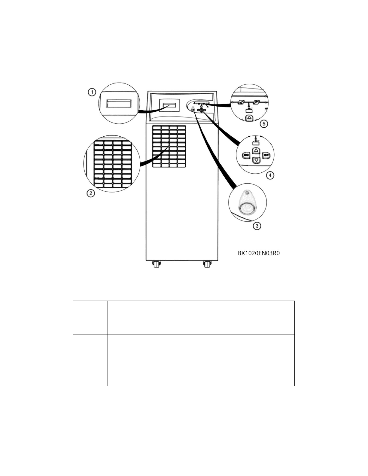
Front View
1
LCD Display
2
Fresh Air Vacuum Grid
3
EPO (Emergency Power Off) Button
4
Menu Navigation Keys
5
Mimic Diagram
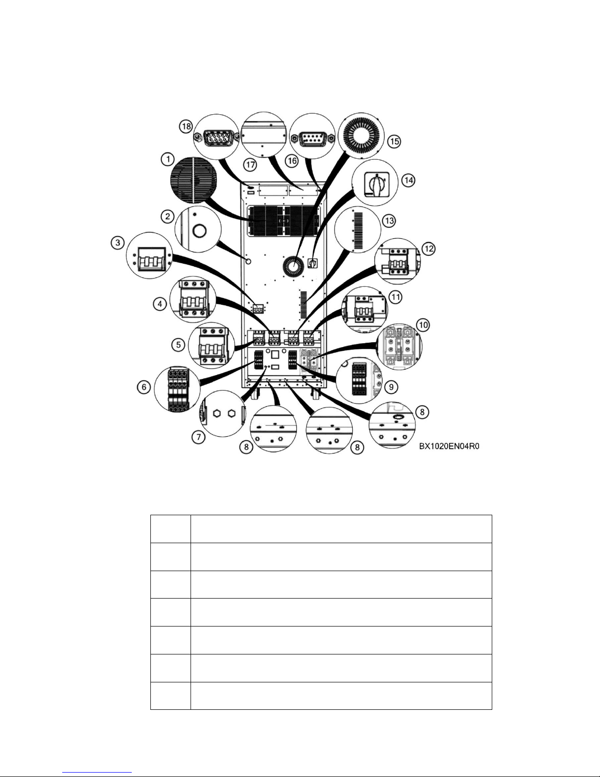
Back View
BOXER SERIES 10-20 KVA PRODUCT DESCRIPTION
AG-SD-109 Publishing Date: 13.10.2015 Revision No: 0 Rev. Date:
1
Rectifier/Charger-Inverter Cooling Fans
2
Bus Bar Charging Button
3
Optional External Bypass Switch
4
Maintenance Bypass Switch
5
Mains Switch
6
Mains Connecting Terminal
7
Ground Connection

BOXER SERIES 10-20 KVA PRODUCT DESCRIPTION
AG-SD-109 Publishing Date: 13.10.2015 Revision No: 0 Rev. Date:
8
Input-Output-Battery Cable Fixing Connectors
9
Output Connecting Terminal
10
Battery Fast Circuit Breakers and Connecting Terminals
11
Battery Commissioning Switch
12
Output Switch
13
Thyristor Hot Air Evacuation Channel
14
Optional Cold Start(Starting through battery) Switch
15
Winding Hot Air Evacuation Channel
16
RS232 Terminal for Communication Software
17
Optional Card Slots
18
Optional Parallel Connection Terminal
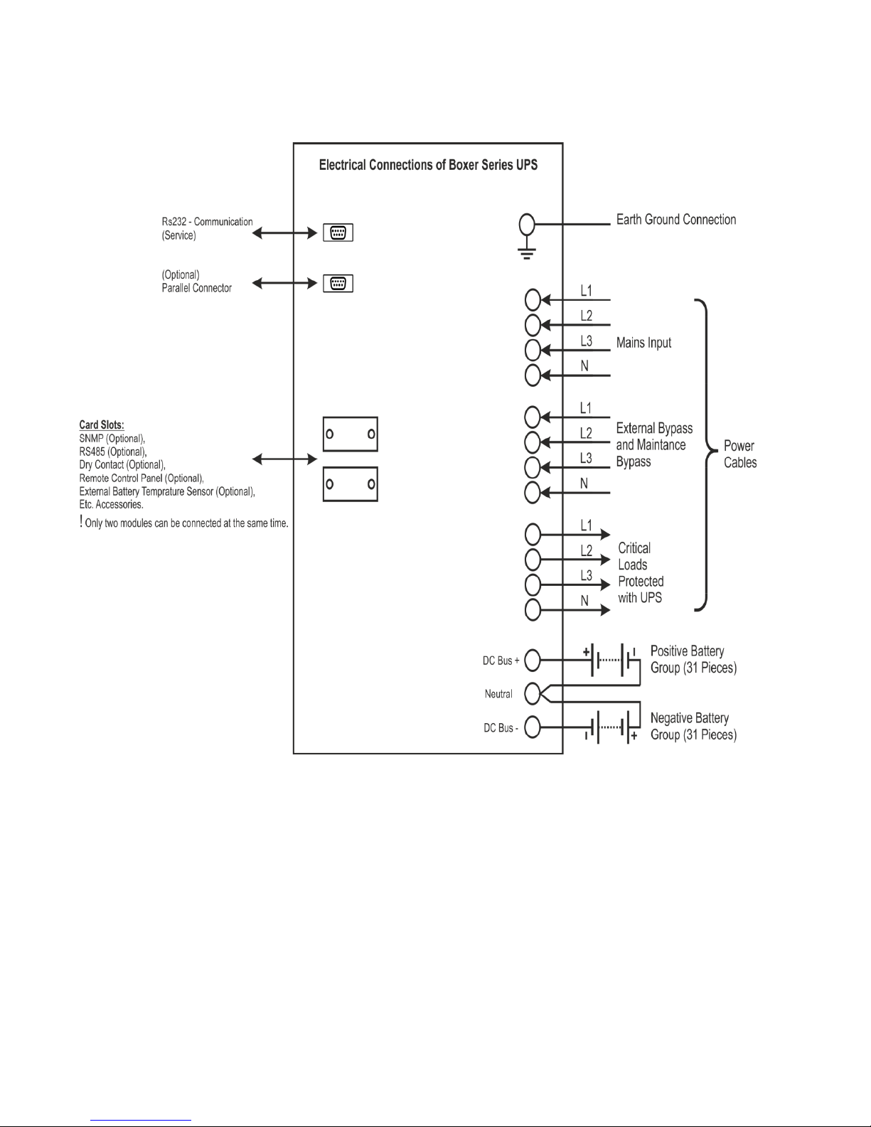
Electrical Connections
BOXER SERIES 10-20 KVA PRODUCT DESCRIPTION
AG-SD-109 Publishing Date: 13.10.2015 Revision No: 0 Rev. Date:
BOXER SERIES 10-20 KVA PRODUCT DESCRIPTION
AG-SD-109 Publishing Date: 13.10.2015 Revision No: 0 Rev. Date:
2.1 General Information
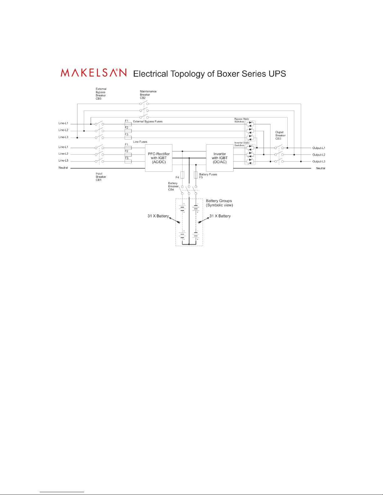
General operation topology of Boxer Series UPS can be recognized as follows:
The UPS is connected to the mains voltage through the CB1 breaker. After this energy has filled
DC bus condensers, the rectifier operates. The rectifier converts the AC mains energy to DC
voltage and charges the batteries in a controlled manner. When there exists no mains, sufficient
level DC bus voltage is created, using battery voltage. DC bus voltage is converted to mains
synchronized AC voltage by the inverter. This is a high quality voltage. Generated AC power are
applied to the loads through the static semi-conductor transfer switches and output (load)
circuit breakers.
When maintenance or repair are needed, before input(CB1) and output (CB3)circuit breakers
are switched to open circuit (OFF), switch the UPS from normal mode to static bypass mode(see
4.1.3.2). Afterwards, the maintenance circuit breaker (CB2) is switched to closed circuit (ON).
After that, output (CB3) and input (CB1) circuit breakers of the UPS are taken to the off position
respectively.
2.1.1 Static Transfer Switch
Some blocks are named as static switches as can be seen above. These blocks consist of inverse
parallel connected thyristors. These switches, which are under the control of the mainboard
control unit, provides controlling of feeding the loads through either mains or inverters. The
loads are fed through inverter during the normal operating mode. Therefore, inverter static
switches are active if there is no problem with the system.
System provides the loads to be fed smooth and seamless by mains or inverter. In order to
manage this process at minimum risk, UPS synchronizes the inverter output and mains bypass

BOXER SERIES 10-20 KVA PRODUCT DESCRIPTION
AG-SD-109 Publishing Date: 13.10.2015 Revision No: 0 Rev. Date:
as the same phase and frequency. Therefore, inverter frequency is the same as mains frequency
as long as it is acceptable within frequency limit.
User can switch between mains and inverter, using the front panel. Loads, operating from the
mains with user instruction, will automatically undertake the load in the event that the mains
cuts off or is out of tolerance.
2.1.2 Battery Temperature Regulation
Our products, in the range of 10-20 kVA, have spaces to place internal battery in their cabinets.
There exists temperature sensor in external battery cabinets. Temperature of these batteries is
measured by this “temperature sensor”. The UPS adjusts battery charge parameters according to
the information of the detected temperature. These parameters can easily be adjusted via LCD in
the system or TELNET interface by authorized staff.
This sensor and the UPS regulates charge parameters in the same way. In this case, we advise
you to order “External Battery Temperature Sensor Kit” for temperature detection of the
UPS.
2.2 UPS’s Operation Modes
Boxer SERIES UPS's on-line and has a double loop structure. Our products operate in the
following modes:
Normal (Online) Mode
Battery Mode
Bypass Mode
Auto Restart Mode
Maintenance Mode
2.2.1 Normal (Online) Mode
In this mode, UPS supplies the load through the inverters. Rectifier unit is fed by the AC mains.
Inverter and battery charger units can be fed by the generated DC supply.
2.2.2 Battery (Stored) Mode
Due to any failure of the mains, while the UPS feeds the critical loads through inverter, this
energy can be supplied from the batteries.
2.2.3 Bypass Mode
On account of UPS overload or any problem on inverter, no qualified AC output is produced and
if bypass voltage and frequency are in tolerance, loads are then fed trough bypass source. UPS
switches from inverter to AC source via static transfer switches without any interruption. The
inverter source and mains must be synchronized in order to manage this switching processes

BOXER SERIES 10-20 KVA PRODUCT DESCRIPTION
AG-SD-109 Publishing Date: 13.10.2015 Revision No: 0 Rev. Date:
without any problem. If inverter output and mains are not synchronized, this switching may take
up to 15 msec. varying according to load type.
2.2.4 Automatic Restart Mode
In case of any failure of the mains, the UPS will continue feeding the critical loads until the
batteries reaches the end of discharge voltage level. The UPS will go on working until the
batteries are drained, and then will shut down. After the mains conditions gets back to normal,
the UPS automatically starts to operate in a period to be determined. In this case, the UPS
continues to operate in normal mode as long as the mains values are in desired criteria. In the
Boxer SERIES UPS, this feature is not activated in factory settings.
2.2.5 Maintenance Mode
The UPS is equipped with a specific protection switch in order to keep the loads powered during
maintenance. This switch is designed so as to handle UPS loads completely.
2.3 Battery Management
Constant Charge Current
Constant current as 1/10 rate of the battery capacity is applied to battery, until the battery
reaches the float charge voltage.
Float Charge
Depending on the battery discharge current, 1/3 of the energy of the battery is charged at this
level. Owing to this level, batteries are kept ready for use at the highest capacity. For lead-acid
batteries, this voltage varies between the values of 2.2-2.35 V/cell. This voltage may differ
slightly due to temperature adaptation. Option of setting this coefficient is provided with our
UPS. If the temperature sensor is used, it is recommended to use.
Deep Discharge Protection
While the system is operating in the battery mode, if battery voltage has dropped below the
deep discharge voltage level, the UPS shuts down and stops absorbing energy from the batteries.
This value varies between 1.6-1.75 V/cell for Lead-Acid batteries, and between 0.9-1.1 V / cell
for Ni-Cd batteries.
Low Battery Warning Level
While the system operates in spare, in other words, battery mode, if the battery capacity drops
below its 40% value with actual loads, it will give audible and visible alarms. This value can be
adjusted by user between 20%-70%.

BOXER SERIES 10-20 KVA PRODUCT DESCRIPTION
AG-SD-109 Publishing Date: 13.10.2015 Revision No: 0 Rev. Date:
2.3.1 Advanced Level Functions (Automatic Battery Test)
The auto battery test automatically discharges 10% of the battery existing capacity in a certain
period defined (default is 90 days). The period between two tests can be adjusted by user
between 30-360 days. At the end of the test, one of these two status, “good or replace” is
determined.
At the end of this test, if batteries are reported as “replace”, then the
batteries are completely drained after the test. In this case, loads can
remain unpowered in case of mains power off.
This test can automatically be started by command from front panel monitor, via telnet interface,
via RS232 smart communication or via UPSMAN (SNMP, see the options).
As a result of all these tests, it is checked whether the batteries that are presently used can
supply the minimum needs of loads in case of the first power-off or not. It is recommended that
test results be checked at regular intervals.
BOXER SERIES 10-20 KVA PRODUCT DESCRIPTION
AG-SD-109 Publishing Date: 13.10.2015 Revision No: 0 Rev. Date:
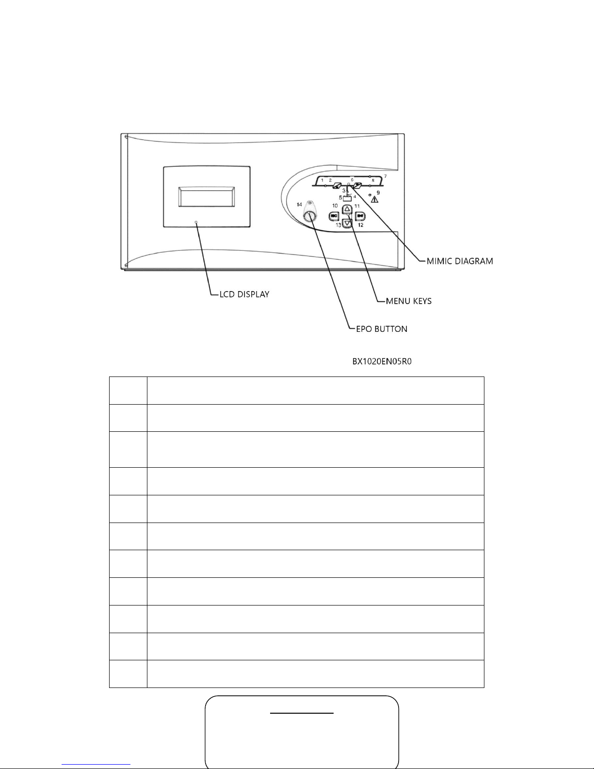
2.4 User Panel
User panel consists of mimic diagram, LCD screen, EPO button and menu keys. The UPS can be
controlled via this panel.
1
Rectifier indicator LED
It constantly illuminates when rectifier works.
2
AC/DC module (Rectifier)
3
Battery discharge indicator LED
It illuminates in battery mode and flashes when UPS is started up through
batteries.
4
Battery charge indicator LED
It illuminates while the batteries are charged.
5
Battery module
6
DC/AC module (Inverter)
7
Bypass static switch indicator LED
It illuminates while the loads are fed through bypass line.
8
Inverter static switch indicator LED
It illuminates when the load is fed by the inverter.
9
Alarm/Warning indicator LED
10-13
Menu keys
14
EPO Button
MAIN SCREEN
Manufacturer –Device Name
Battery Charge Status as Percentage
Load Status as Percentage
Period of Working from Battery

BOXER SERIES 10-20 KVA PRODUCT DESCRIPTION
AG-SD-109 Publishing Date: 13.10.2015 Revision No: 0 Rev. Date:
Menu Flow Chart
* Detailed service menu can only be opened by the authorized service staff.
Control Menu
Status Menu
Setup Menu
Logging Menu
CONTROL
Start
Stop
Switch to Bypass
Switch to UPS
Quick Battery Test
Battery Status Test
Stop Battery Test
STATUS
Mains
Output
Bypass
Battery
Temperature
Inverter
DC Bus
Alarms
SETUP
Date & Time
Battery Install Date
Auto Restart
Auto Battery Test
Screen
Warning Beep
Language
Communication
Service Menu*
Version
LOGGING
Log Code
Date
Time
Log Records
Information
MAINS
Voltage
Current
Frequency
Active Power
Reactive Power
Apparent Power
ALARMS
Actual Alarms
BATTERY
Current
Temperature
Voltage
Charge Percentage
Test Type Number
Test Date and Time
Capacity
Battery Status
Next Test Date
Next Test Time Counter
INVERTER
Voltage
Current
Active Power
TEMPERATURE
Rectifier
Inverter
Bypass
Ambient
Battery
BYPASS
Voltage
Current
Frequency
DC BUS
Voltage
Active Alarms
OUTPUT
Voltage
Current
Frequency
Active Power
Reactive Power
Power Factor
Apparent Power
Load Percentage
Crest Factor

BOXER SERIES 10-20 KVA PRODUCT DESCRIPTION
AG-SD-109 Publishing Date: 13.10.2015 Revision No: 0 Rev. Date:
2.4.1 Opening Screen
When the front panel monitor is turned
on, firstly opening screen is observed.
Model name, charge status, load status
and remaining back-up time are
displayed. In case of any alarm case,
alarms are shown as scrolling text in the
first line. If no button is pressed for 5
minutes, system returns to the opening
screen.
2.4.2 Main Menu
Switch from opening screen to the main
menu through ENT button.
2.4.3 Navigating Through the
Menus
Press UP/DOWN keys to move the
cursor arrow in the screen.
Open a sub-menu with ENT button, go
back to the previous menu with ESC
button. Control sub-menu is
shown on left. Some menus consist of
more than one page. Switch among the
pages with UP/DOWN buttons.
Some menus have changeable options
like ON/OFF, durations or quantities.
To change setup in such menus, choose
variable with ENT, set new value with
UP/DOWN buttons and save it with
ENT button. Cancel with ESC button.

BOXER SERIES 10-20 KVA PRODUCT DESCRIPTION
AG-SD-109 Publishing Date: 13.10.2015 Revision No: 0 Rev. Date:
2.4.4 Password Protected Menus
Some menus such as the control menu
are password protected. To enter
password choose each digit with
UP/DOWN buttons and confirm with
ENT button.
User level password is: 0000
2.4.5 Control Menu
The followings can be done in the control menu:
Start Start the UPS.
Stop Stop the UPS.
Switch to BYPASS Switch to static BYPASS mode.
Switch to UPS Switch to online mode.
Bat. Quick Test Start the quick battery test.
Bat. Capacity Test Start the deep battery test.
Stop Battery Test Stop the battery test.
Battery status test, drains the 10% of battery energy and reports batteries which has more
capacity than 10% as “Good”, less capacity than 10% as “Replace” according to the test results.
After the device is started and every 24 hours, it automatically performs a quick battery test, if
test counter value is zero.
Note: Batteries must have been fully charged and kept in floating situation for 1 hour before
performing the quick battery test.
Batteries must have been fully charged and kept in floating situation for 5 hour before
performing the battery status test.
Battery tests are performed by directing the power to the mains, independently from the loads.
If the mains values gets out of limits during the test, test is cancelled.
Following Status> Battery menu, how
many minutes left to start the test can
be observed.
If “Stop Battery Test” is chosen from
the menu, the UPS cancels the battery
test and goes back to the previous
operating state.
2.4.6 Status Menu

BOXER SERIES 10-20 KVA PRODUCT DESCRIPTION
AG-SD-109 Publishing Date: 13.10.2015 Revision No: 0 Rev. Date:
The mains, output, bypass, battery, inverter, DC bus and alarms can be displayed on this menu.
Mains
VP, A Hz Voltage (phase-neutral), current and frequency of each phase.
KW, KVA, PF Active power, reactive power and power factor of each phase.
Pt, St, VL Total active power and apparent power, voltage of each phase
(phase-phase).
Output
VP, A, Hz Voltage (phase-neutral), current and frequency of each phase.
KW, KVA, PF Active power, reactive power and power factor of each phase.
Pt, St, %L Total active power, total apparent power and load, in percentage,
of each phase.
VL, CF Voltage of each phase (phase-neutral) and crest factor.
Bypass
VP, A Hz Voltage (phase-neutral), current and frequency of each phase.
VL Voltage of each phase (phase-phase).
Battery
A, °C, V, Charge% Charge flow, temperature, voltage and charge percentage.
SXXXX, DD/MM/YY, Test type number, date and time. Batter capacity and status.
SS: DD, Capacity, Status
Next Test, time Next test date and count down for battery test in floating status.
Temperature
°C,°C,°C,°C,°C Rectifier, inverter, Bypass, ambient and battery temperatures.
Inverter
VP, A, KW Voltage (phase-neutral), current and active powers of each phase.
DC Bus
P, N Positive bus voltage, Negative bus voltage.
Alarms Active UPS alarms.
2.4.7 Setup Menu
The following adjustments can be performed via setup menu:

BOXER SERIES 10-20 KVA PRODUCT DESCRIPTION
AG-SD-109 Publishing Date: 13.10.2015 Revision No: 0 Rev. Date:
Date & Time
To set date and time, use up and down
keys to choose the variable you want to
set and press ENT.
Set the value via arrow buttons and
press ENT button again.
Battery Installation Date
When new batteries are installed, set
the battery install date via this menu.
Automatic Restart
In battery mode, the device operates
until batteries discharge and then shuts
down. Auto-restart can be used to
restart
the UPS automatically when the mains
gets back into limit values.
Open/close auto restart via the option
of ON/OFF and determine how much
time after the device will be started
after the mains is normal.
Automatic Battery Test
Use this menu to open/close automatic
battery test and to set the period
(repeat period for the regular test)
independently from user.
Screen

BOXER SERIES 10-20 KVA PRODUCT DESCRIPTION
AG-SD-109 Publishing Date: 13.10.2015 Revision No: 0 Rev. Date:
Change the screen contrast setting to make it more visible on different environmental
conditions.
Beeper
Turn the beeper sound on/off.
Language
Set the menu language.
Communication
Set the protocol for the RS232
connection. The options are SEC and
Telnet.
Service Menu
Service menu is password protected. It
can only be accessed by authorized
service staff.
Version

BOXER SERIES 10-20 KVA PRODUCT DESCRIPTION
AG-SD-109 Publishing Date: 13.10.2015 Revision No: 0 Rev. Date:
Inverter, rectifier, CPLD, front panel
software version and UPS serial no,
device apparent power (KVA), nominal
output voltage (phase-neutral), nominal
output frequency (Hz); parallel battery
handle number x series battery handle
number and battery capacity set on the
UPS can be accessed through the version menu.
2.4.8 Logging Menu
The last 500 logs can be observed in the
logging menu.
While observing any of the logs, if ENT
button is pressed, all details regarding
the moment of the event (mains,
battery, bypass, output values, alarms
etc.) can be seen.
Older/actual logs can be observed,
using UP/DOWN buttons.

BOXER SERIES10-20 KVA INSTALLATION
AG-SD-109 Publishing Date: 13.10.2015 Revision No: 0 Rev. Date:
3 INSTALLATION
3.1 Single Module Installation
In this section, warnings which you must follow and the checks which you must perform before
starting-up the device are stated. Additionally, you can find information concerning the points
you must pay attention to during carrying style for cabinets, positioning and connections.
3.1.1 Warnings
The UPS must be installed by the personnel approved by MAKELSAN.
Warranty is not valid for the devices installed by unauthorized
personnel.
BATTERY HAZARD!
In some models, during operation of battery and the UPS together, there may exist battery
terminal voltages reaching up to 450 VDC.
Precautions must be taken in order to protect eyes against electrical arcs that can result from
contacts.
ESD-protected rubber gloves should be used.
Batteries discharging or leaking must not be used, if any, it must be replaced. Uninstalled
batteries must be kept, carried and transferred to destruction points safely.
In case of skin contact with elector liquid, immediately rinse the exposed skin part with water.
Operator must remove any dangerous accessories such as ring, watch etc. before working on the
device.
The product needs three phase and four cable (+ground) supply system for input. Type of this
supply system conforms to IEC60364-3 standards. The devices have transformers which
haveability to optionally convert from three cable to four cable system. Provided that IT AC
power distribution will be installed, 4 pole-circuit breaker must be used. More detailed
explanations concerning the topic can be found in the standard named as IEC60364-3.

BOXER SERIES10-20 KVA INSTALLATION
AG-SD-109 Publishing Date: 13.10.2015 Revision No: 0 Rev. Date:
3.1.2 Pre-Installation Check Up
Before installing the UPS product, the following checks should be carried on. These are the first
and important steps in the operation of the product correctly.
Definitely check whether or not any damage was done to internal and external structures
of the UPS, accessories and batteries during transportation or shipment. Report any
damages before receiving.
Make sure that the product is the right model. Check whether the label behind the device
matches with the product ordered or not.
3.1.3 Positioning
The UPS and the batteries are designed for indoor use, and must be placed on a clean area with
cool air flow.
3.1.3.1 Positioning the UPS
For the Boxer 10-20 KVA Series, fresh and cool air enters the device from the front side and goes
out through the fans on the back side of the device. Air entrance and exit points should never be
closed. It must be positioned on a place where is protected from water or similar liquid contact
risks.
If the area is very dusty, filters optional provided must be used. Usage of these filters must be
done according to the relevant instructions.
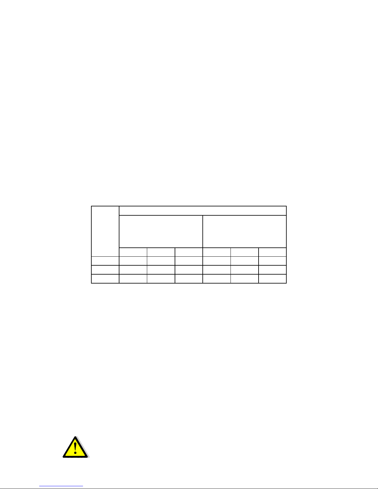
The UPS is structurally a losing-energy system. Lost energy occurs as temperature. How forced
air cooling system is needed is provided in the following table. Using the table, what capacity of
air conditioned should be used to cool the place where the UPS is can be determined.
Device
BTU/h amount for
cooling
Estimated BTU/h value
For 100%Bridge Load
(Non-Linear Load) Operation
10KVA
2,663
3,196
15KVA
3,790
4,548
20KVA
3,892
4,670

BOXER SERIES10-20 KVA INSTALLATION
AG-SD-109 Publishing Date: 13.10.2015 Revision No: 0 Rev. Date:
3.1.3.2 Configuration of Internal Batteries
The 10-20 kVA UPS can be configured through 64 4,5Ah, 7Ah or 9Ah standard batteries as seen
in the following table:
BOXER INTERNAL BATTERY USAGE TABLE
Device Power (KVA)
10
15
20
Series Battery Number
31
31
31
Battery Group 2 2
2
Total Battery Number
62
62
62
I_bat.max @V_bat_cutoff(A)
12,5
18,8
25,1
Recommended Internal Fuse (A)
20
32
40
Recommended Rear Cover Fuse(A)
20
32
40
* These cells are battery configurations recommended.
*Type being able to perform fast and semi-conductor protection is used in battery fuses.
Positioning forms of 7/9 Ah and 4, 5 Ah batteries inside the UPS can be seen in detail in the
following figures:

BOXER SERIES10-20 KVA INSTALLATION
AG-SD-109 Publishing Date: 13.10.2015 Revision No: 0 Rev. Date:
3.1.3.3 Placing External Batteries
Batteries should be mounted in an environment where the temperature is consistent and even
over the whole battery. Temperature is a major factor directly affecting the battery life and
capacity. In general, battery manufacturers recommend that batteries be used in 20-25 °C.
Furthermore, battery manufacturer companies indicate the performance of batteries according
to the said temperature range. If the temperature exceeds the said range, the life of the battery
will decrease. On the contrary, again if the temperature drops the said range, the capacity of the
battery will seriously decline. Therefore, expected time will not be obtained during back up. As a
result, keep batteries away from heat sources and serious air flows. Pay attention to the said
factors and be careful about and observe the following points in terms of external connections of
the batteries:
Keep batteries away from main heat sources.
Keep batteries away from serious air flows.
Keep batteries away from the humid places. Hereby batteries can be prevented from
terminal oxidations and possible leakage currents.
Please use aR or gR semi-conductor type fuse at the battery rooms and cabinets.
If it is possible, please use breaker switch without fuse for the battery cabinet.
Keep battery cabinets and shelves high above the ground. UPS should be protected
against possible floods or liquid contacts.

BOXER SERIES10-20 KVA INSTALLATION
AG-SD-109 Publishing Date: 13.10.2015 Revision No: 0 Rev. Date:
Battery rooms should be properly ventilated.
Shelves will be accessible in touch if batteries are in battery room. Therefore, please
keep restricted accessing to battery rooms. Use necessary safety writings and strips.
Especially, for the external cabinet batteries system of UPS, fuses must definitely be used. These
fuses must be mounted as close as possible to the batteries. This closeness will increase the
electrical operation safety with the battery.
BOXER EXTERNAL BATTERY CABINET CONFIGURATION
Device Rating (kVA)
10
15
20
Batteries in series
31
31
31
Independent Group Number
2 2 2
Total number of Battery
62
62
62
I_charge_max@V_bat._max(A)
2,3
3,4
4,5
I_bat._max@V_bat._cut off(A)
13
19
26
Recommended external cabinet fuse (A)
20
32
40
External battery cabinet and battery room applications are given below as an example. The
application form may vary according to the customer.

BOXER SERIES10-20 KVA INSTALLATION
AG-SD-109 Publishing Date: 13.10.2015 Revision No: 0 Rev. Date:
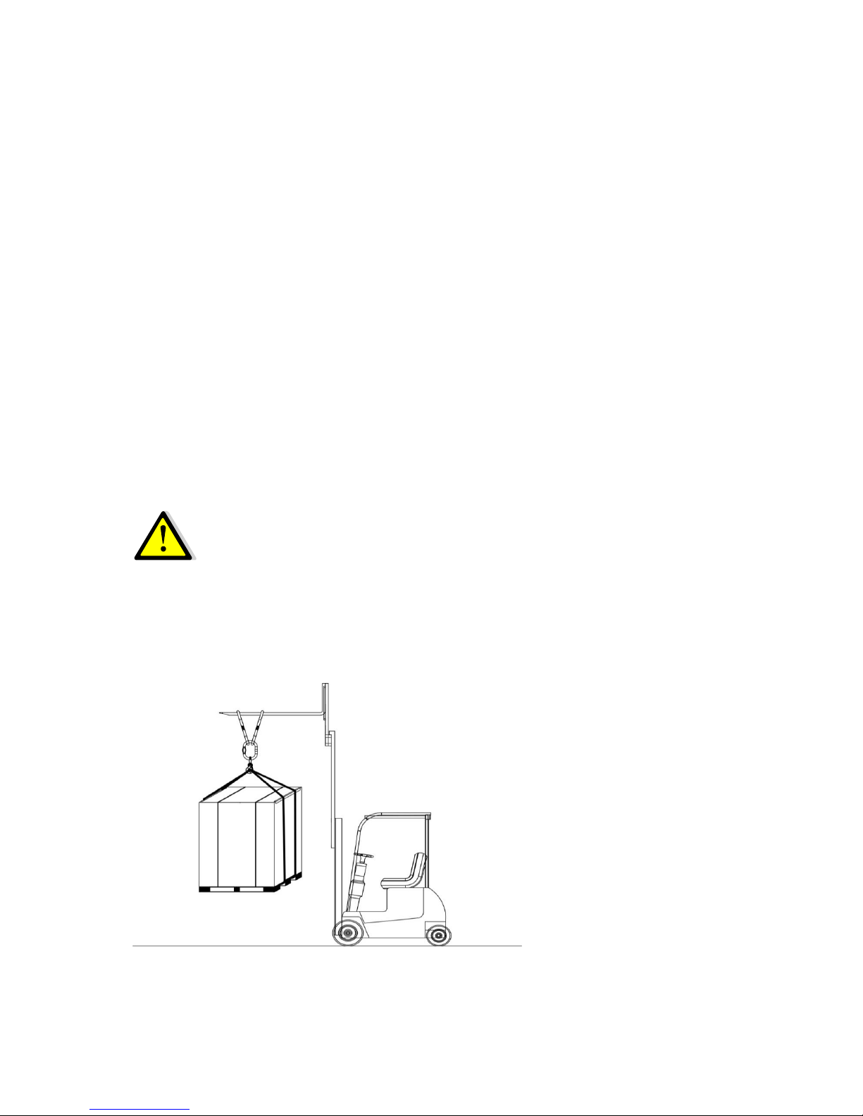
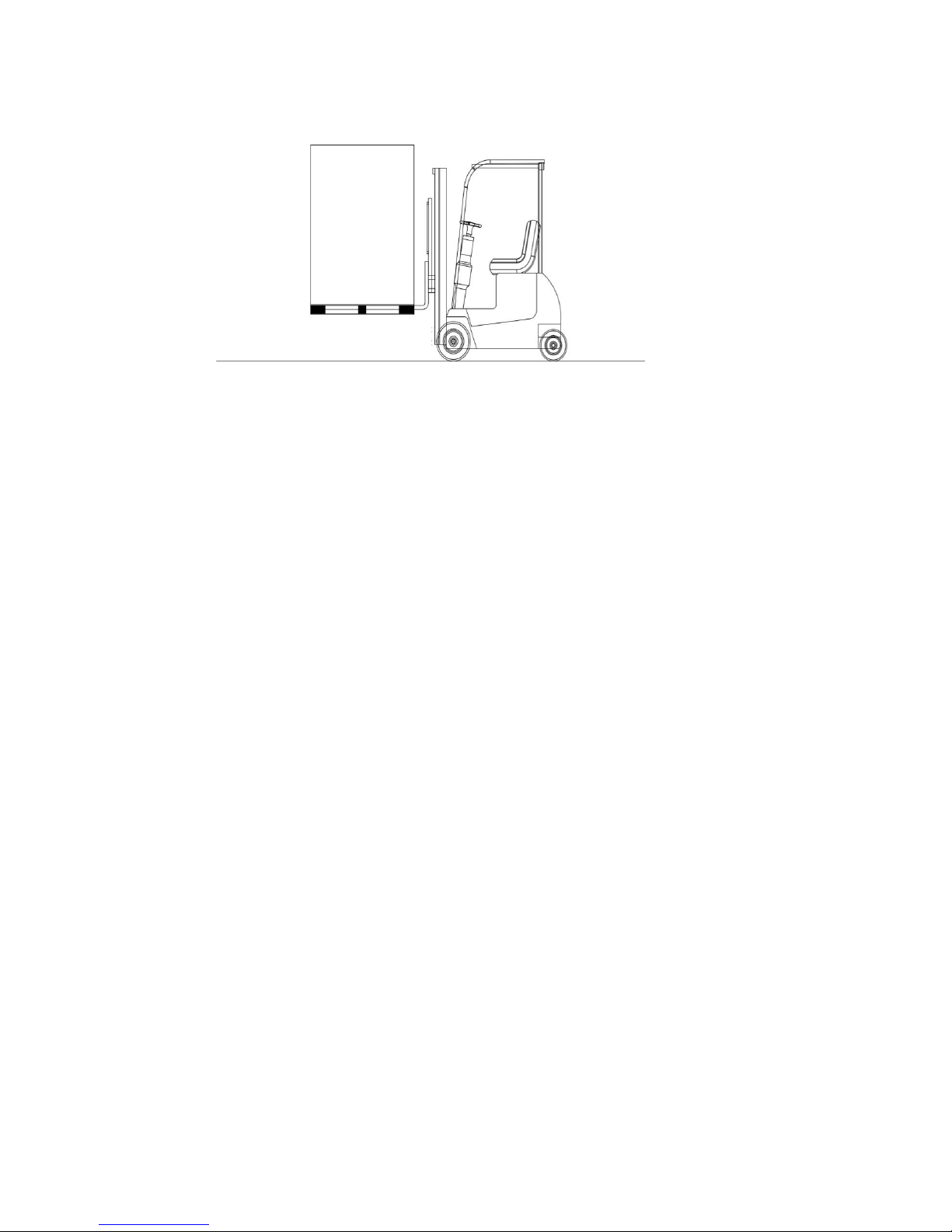
3.1.4 Transportation Type of Cabinets
Pay attention that carrying vehicles or handling accessories must have enough features and
characteristics to carry the weight of the UPS.
UPS and optional battery cabinets are designed to be carried by a forklift or similar vehicles.
In addition, the UPS can be carried through its own wheels in short distances. Be more careful of
sudden movements, especially when batteries are inside of cabinet.
Move the UPS as rarely as possible.
3.1.5 Mains, Load and Battery Connections
Distribution board is recommended for the UPS outputs. Load protection fuses and breakers
must be used in such distribution board. Additionally, fuses with various speeds may be needed
according to load. A-B type fuses or magnetic breakers are recommended to be used if the load is
suitable.
3.1.5.1 External Protections
To protect the AC inputs, thermal magnetic breakers or V-automat breakers must be
independently installed on the distribution board. Herein, the cable intersections and fuse values
must be determined and connected by an expert authorized person.
BOXER SERIES10-20 KVA INSTALLATION
AG-SD-109 Publishing Date: 13.10.2015 Revision No: 0 Rev. Date:
Over current protecting must be installed on mains input board. This protection must be
selected in conformity with the bearing capacity of over current and over load of the UPS.
The fuses in the board must be chosen as 135% higher rated than the current values given in the
table below, and the fuses must be C-type (slow).
Ground leakages flow to the ground through the EMI filters on the input and the output of the
UPS. Accordingly, MAKELSAN recommends a residual current relay over 300mA.
The residual current relays to be placed in the UPS input must also be:
Resistant to both positive and negative DC pulses,
Not sensitive to transient currents.
Must be sensitive to currents which is average between 0, 3-1 ampere.
3.1.5.2 Cable and Fuse Configuration
Cable designs must be compatible to current and voltage values stated herein, additionally local
instructions must be obeyed about these topics.
UPS
Rating
(KVA)
Rated Currents (A)
Mains Currents at Maximum
Battery Charge (3 phase +
neutral)
Output Currents under Full
Load (3 phase + neutral)
380V
400V
415V
380V
400V
415V
10
17,1
16,2
15,7
15,4
14,6
14,1
15
25,6
24,4
23,5
23,1
21,9
21,1
20
34,2
32,5
31,3
30,8
29,2
28,2
Non-linear loads (loads such as computer) may affect cable section design. Their neutral
currents might be more than phase currents, even may rise up to 1.5 times the phase current.
Each cabinet must be, directly and as short as possible, to ground line by means of protection
ground cable. Typical ground cable cross sections are 2,5 mm2 for 10 kVA and 6 mm2 for 15 kVA
and 10 mm2for 20 kVA. It is recommended that cable length not exceed 5 meters.
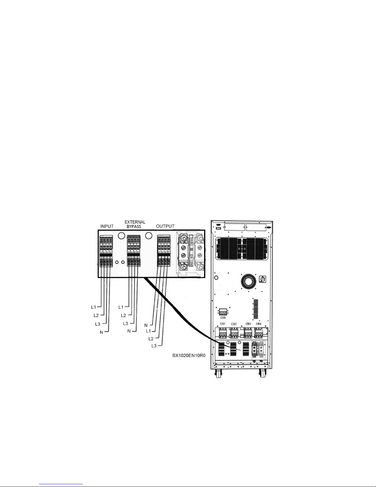
3.1.5.3 Cable Connections
UPS input, output and battery connection inlets are made from the rear side of the UPS. Cable
connections are performed after the big cover at the back of the device has been removed.

BOXER SERIES10-20 KVA INSTALLATION
AG-SD-109 Publishing Date: 13.10.2015 Revision No: 0 Rev. Date:
ATTENTION! 3 pole-circuit breakers (switch) are used for the input and
output of the UPS, Neutral line is not interrupted.
Please, follow the steps below for electrical
connections:
1. Take all the breakers in the distribution boards
open circuit (OFF) position and make sure that loads
and the mains are isolated from cables
2. Remove the screws of the metal cover at the back of the UPS and take the board from its place.

BOXER SERIES10-20 KVA INSTALLATION
AG-SD-109 Publishing Date: 13.10.2015 Revision No: 0 Rev. Date:
3. Connect the ground cable.
4. Make sure that all the circuit breakers are in the open circuit (OFF) position. The use of these
circuit breakers are explained in the next sections.
BOXER SERIES10-20 KVA INSTALLATION
AG-SD-109 Publishing Date: 13.10.2015 Revision No: 0 Rev. Date:
5. Connect the input cables:
R phase to INPUT L1,
S phase to INPUT L2,
T phase to INPUT L3,
N(Neutral) to Input N.
6. Check the phase sequence.
7.Repeat steps 4-5 for output cables.
8. Place the metal cover back and tighten its screws.
Use the cable clips to stabilize the cables when the connections are done.

BOXER SERIES10-20 KVA INSTALLATION
AG-SD-109 Publishing Date: 13.10.2015 Revision No: 0 Rev. Date:
Make sure that the loads in the output of the UPS prepared are isolated
during the connection if they are not ready to be connected yet.
Before the UPS is started, make sure that cable connections have been made
in accordance with the warnings in boards. Additionally, check if there is
isolated transformer at the input of UPS and consider the local directions.
Make sure that grounding has been made properly. Wrong works or
grounding made may damage the UPS and other systems in the installation.
3.1.5.4 Connecting Batteries
You can find details about internal and external batteries installation procedure and connections
in this section.
3.1.5.4.1 Internal Battery Installation Procedure and Connection
Battery Installation Procedure
Follow the procedure below while commissioning internal batteries:
1. Remove battery fuse.
2. Make sure that serial and parallel connections of internal batteries are proper.
3. Connect the “- terminal” of the battery to the freed cable inside, named as “-BAT”, properly.
4. Connect the “+ terminal” of the battery to the freed cable inside, named as “+BAT”, properly.
5. Check battery connections once more and make sure that the poles are properly connected.
Avoid short circuiting batteries.
Exploding batteries can damage you and your environment!
Battery terminal may rise up to 450 Vdc!
6. Place the rear cover back and screw on completely.
Internal Battery Temperature Sensor
Information concerning temperature of internal batteries is read through NTC placed in the J26
socket of the main control board.

BOXER SERIES10-20 KVA INSTALLATION
AG-SD-109 Publishing Date: 13.10.2015 Revision No: 0 Rev. Date:
See the chapter of options for control of external batteries.
3.1.5.4.2 External Battery Installation Procedure and Connection
You can find details about how to configure the external batteries under “External Batteries
Configuration” title above. The information about connection of external batteries and UPS is
given in this section.
Avoid short circuiting batteries.
Exploding batteries can damage you and your environment!
Battery terminal may rise up to 450 Vdc!
1. Switch “CB4” breaker on the UPS to the position of open circuit (OFF).

BOXER SERIES10-20 KVA INSTALLATION
AG-SD-109 Publishing Date: 13.10.2015 Revision No: 0 Rev. Date:
2. If there is, switch breakers on the battery cabinet to the position of open circuit (OFF).
3. Remove the battery fuse on the battery cabinet.
4. Remove battery fuse on the UPS.
5. Make sure of serial and parallel connections of external battery packs are correct.
6. Connect the cable to terminals of two of the UPS, "N” (Battery Neutral)”, one "+BAT" and one
"- BAT" respectively.
7. Connect four cables that come from UPS to terminals on external battery cabinet or in battery
room according to external battery connection diagram below. As follows:
N(UPS) ----- Positive Battery Group "-" terminal
N(UPS) ----- Negative Battery Group "+" terminal
“+ BAT” ----- Positive Battery Group “+“ terminal
“-BAT” ----- Negative Battery Group "-" Terminal
8. Make sure that the polarities are connected correctly by checking battery connections for the
last time.
9. Replace battery fuse on UPS.
10. Replace battery fuse on battery cabinet.
11. If there is, switch breakers on the battery cabinet to the position of closed circuit (ON).
12. Check if there is appropriate battery voltages to the battery input terminals of the UPS by
means of a proper measuring device.
External battery cable selection is determined by application. Fuses which are recommended for
the UPS and battery cabinet are given. To connect to these type fuses, the lowest diameter cables
are suggested. Please, refer to the standard called EN 50525-2-31(VDE 0100-430) in this subject.
The selection should be such that the cable will allow at most 0.5 Vdc decreasing.
There exists "External Battery Temperature Measurement Kit" to provide optimization of
the batteries according to battery temperatures in the external battery cabinet application. Thus,
battery charge temperature can be optimized according to the temperature.
External battery connection scheme is given below:

BOXER SERIES10-20 KVA INSTALLATION
AG-SD-109 Publishing Date: 13.10.2015 Revision No: 0 Rev. Date:
3.1.5.5 Control and Communication Cable Connections
MAKELSAN UPS products have standard or optional connections of advanced external battery
cabinet, environmental monitoring, control panels and various intelligent monitoring.
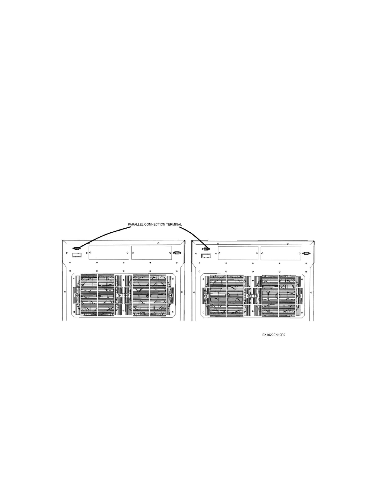
Connections at the rear side of the UPS:
One RS232 serial communication bus (Standard),
Two expansion slots (Optional),
One PARALLEL port (standard).

BOXER SERIES10-20 KVA INSTALLATION
AG-SD-109 Publishing Date: 13.10.2015 Revision No: 0 Rev. Date:
3.2 Parallel Setup
The product which you have bought can be operated in parallel; however, this feature is offered
as an option. Please contact your authorized dealer for parallel operation.
Parallel application should be made by authorized personnel assigned by
MAKELSAN!
In case of need of redundancy or more power, Boxer SERIES devices can be operated as parallel
up to the amount of 8. A principle scheme which shows a system in which two UPS are
connected in parallel is given below:

BOXER SERIES10-20 KVA INSTALLATION
AG-SD-109 Publishing Date: 13.10.2015 Revision No: 0 Rev. Date:
Input and output of more than one device are connected to each other; but definitely each
battery group is different from another, batteries cannot be used in common. The following
points should be considered while placement of devices in parallel system and their electrical
connections are made:
The devices which are connected in parallel must be from the same series and must have
the same rated power.

BOXER SERIES10-20 KVA INSTALLATION
AG-SD-109 Publishing Date: 13.10.2015 Revision No: 0 Rev. Date:
Devices must be running on the firmware with the same version and revision codes,
devices operating with old firmware must be updated.
Devices must be located as close possible as to each other (maximum 6 * 110 cm
paralleling cables.)
Each device must have its own neutral cable.
Each device must have its own ground cable.
Devices must be connected through the distribution board and phases must be properly
connected. (U1-U2-…-UN), (V1-V2-…-VN), (W1-W2-…-WN).
Same battery group must not be connected to devices more than one
For equal current sharing, all cables with which the devices are connected to the board
must be equal in length and cross section.
Parallel Settings
Connect the parallel cable as shown in figure below. Only use the cables provided by MAKELSAN.
BOXER SERIES10-20 KVA INSTALLATION
AG-SD-109 Publishing Date: 13.10.2015 Revision No: 0 Rev. Date:
Software settings on the user panel should be made by authorized personnel.
BOXER SERIES 10-20 KVA EXPLANATIONS OF LOGGING
AG-SD-109 Publishing Date: 13.10.2015 Revision No: 0 Rev. Date:
4 OPERATION
4.1 Operation Procedure
You can find information about circuit breaker, first start-up, types of UPS operation tests,
turning UPS off, EPO and RS232 serial communication system in this section.
4.1.1 Circuit Breakers
The UPS has four circuit breakers accessible from the rear side. These are used for the AC input,
maintenance Bypass, output and the battery connections respectively.
Three-phase AC voltage is applied through CB1 to input of UPS.
AC input voltage will be applied directly to loads through CB2. In this way, maintenance
purposed switching is done properly. Owing to the auxiliary contact detail in CB3, if it is
activated while the UPS is operating, the mains activates Bypass static switches. The system
switches to maintenance mode without any interruption.
CB3 is used to connect or separate AC voltage that come from static switches
to the loads on UPS.
External batteries are connected to UPS through CB4.
Active Breakers
Operation Mode
Explanation
CB1, CB3, CB4, CB5*
Normal Mode
UPS operates in normal mode.
CB1, CB3, CB4, CB5*
Static Bypass Mode
UPS is overload, loads will be transferred to
static bypass line temporarily.
CB2
Maintenance Mode
UPS is shut down for maintenance,
maintenance is supplied through Bypass.
*CB5-External Bypass switch is optional.
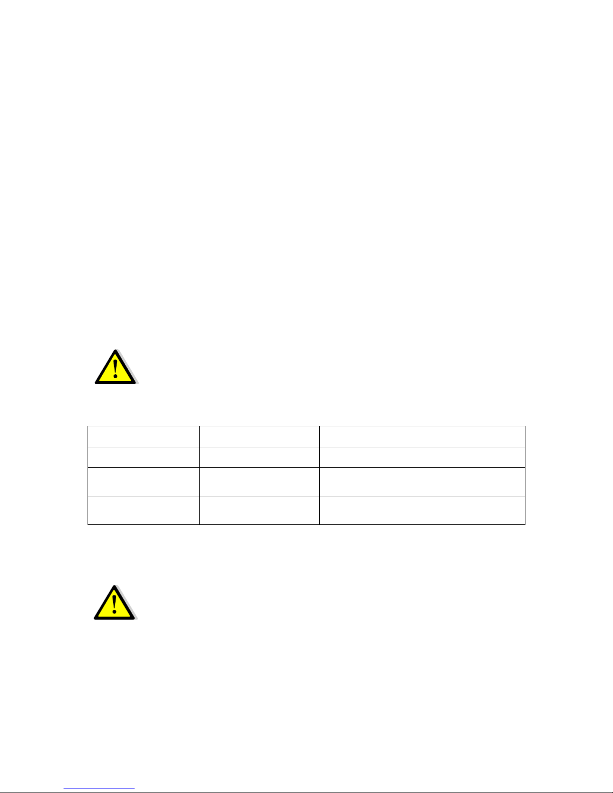
4.1.2 First Start-Up
Wait at least 5 seconds between each step.
1. Switch all the breakers to open circuit (OFF) position.
2. Push the Soft Start button (SW1) for 10 seconds at least.
BOXER SERIES 10-20 KVA EXPLANATIONS OF LOGGING
AG-SD-109 Publishing Date: 13.10.2015 Revision No: 0 Rev. Date:
3. Switch the input breaker (CB1) to closed circuit (ON) position. If there exists optional external
bypass, switch the external bypass breaker (CB5) to closed circuit (ON) position.
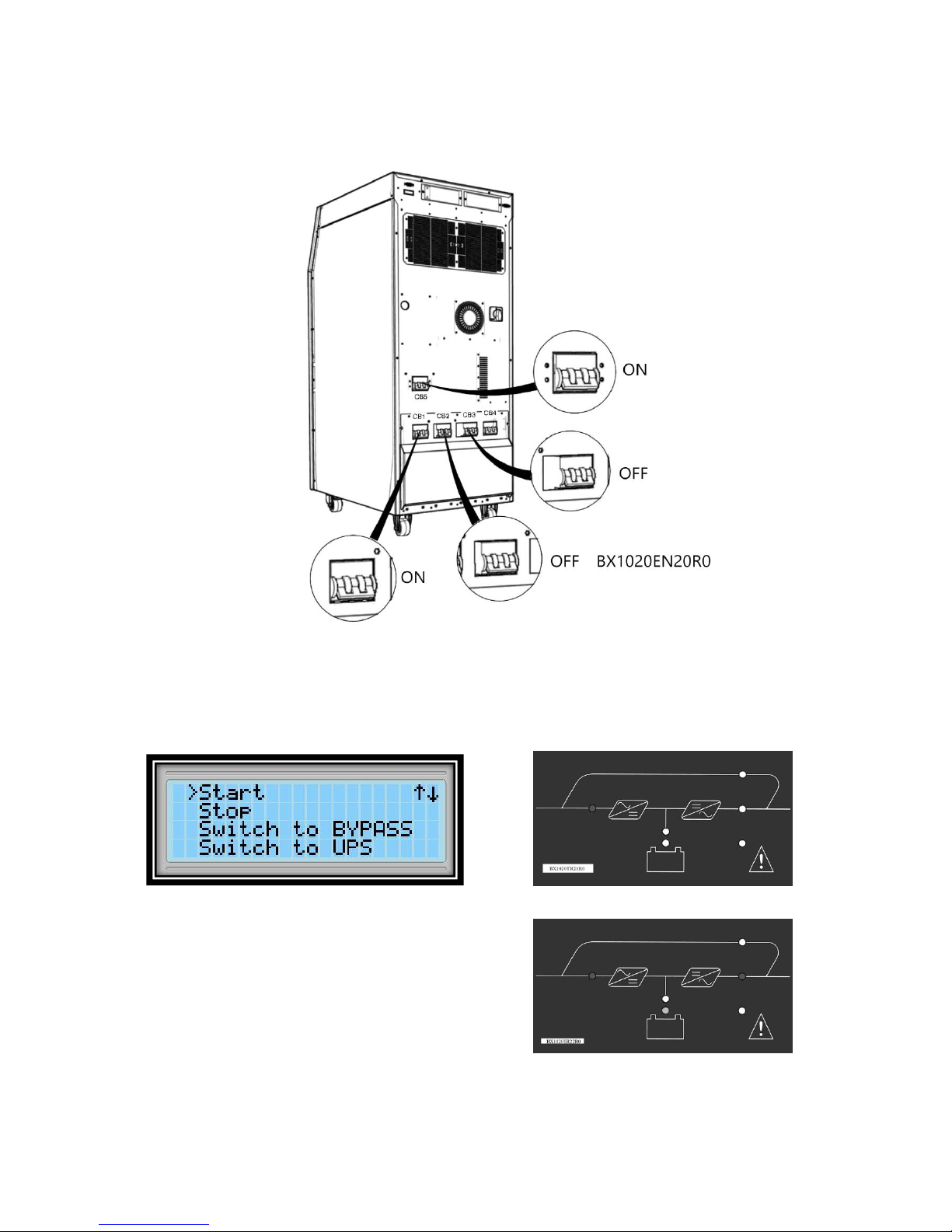
4. Start the UPS using the front panel.
Main Menu>Control>Password>Start
5. Check the device has switched to normal operation
mode, via front panel display LEDs and LCD panel.
6. Switch battery circuit breaker (CB4) to closed circuit (ON) position.

BOXER SERIES 10-20 KVA EXPLANATIONS OF LOGGING
AG-SD-109 Publishing Date: 13.10.2015 Revision No: 0 Rev. Date:
7. Switch output circuit breaker (CB3) to closed circuit (ON) position.
8. You can turn on the loads connected to the device.
After all these steps, check that load is fed through inverter static switches via mimic diagram. In
a contrary situation, check UPS total and phase loads. The UPS gives audio alerts in an overload
condition, without feeding critical AC loads.
4.1.3 Testing the Operation Modes of the UPS
After first start-up, switch among operation modes with the aim of control.
4.1.3.1 Switching from Normal Mode to Battery Mode
Take CB1 to open circuit (OFF) position. This action cuts off the mains voltage and the UPS starts
operating on battery mode. After checking the operation, take CB1 to closed circuit (ON)
position again.
4.1.3.2 Switching from Normal Mode to Static Bypass Mode
Switch the UPS to bypass mode via user panel. Check if static bypass led has flashed in mimic
diagram.

BOXER SERIES 10-20 KVA EXPLANATIONS OF LOGGING
AG-SD-109 Publishing Date: 13.10.2015 Revision No: 0 Rev. Date:
Main Menu>Control> Switch to BYPASS
Note: The UPS will not switch to bypass mode if the mains is out of limits or phases are wrongly
connected.
4.1.3.3 Switching from Static Bypass Mode to Normal Mode
Switch the device to UPS mode via user panel. Verify the case through mimic diagram.
Main Menu>Control> Switch to UPS
Note: The inverter will not undertake the load if the inverter voltage is out of limits or there is
overload or over temperature situation.
4.1.3.4 Switching from Normal Mode to Maintenance Bypass Mode
Make sure that the inverter output is synchronized with the maintenance
bypass line before switching to maintenance bypass mode. Otherwise, there
is a possibility of cutting off the load power for a short while.
Switch the device to static Bypass mode using the front panel. Check If static
bypass led has flashed in mimic diagram.

BOXER SERIES 10-20 KVA EXPLANATIONS OF LOGGING
AG-SD-109 Publishing Date: 13.10.2015 Revision No: 0 Rev. Date:
Main Menu>Control> Switch to BYPASS
1. Take CB2 to closed circuit (ON) position.
2. Stop the UPS using the front panel.
Main Menu>Control >Password>Stop

BOXER SERIES 10-20 KVA EXPLANATIONS OF LOGGING
AG-SD-109 Publishing Date: 13.10.2015 Revision No: 0 Rev. Date:
3. Switch CB1, CB3 and CB4 to open circuit (OFF) position.
FOR SAFETY, WAIT 5 MINUTES AT LEAST BEFORE OPENING UP THE DEVICE
AFTER YOU HAVE SWITCHED THE DEVICE TO THE MAINTENANCE BYPASS
MODE.
4.1.4 Performing a Complete Shutdown
1. Turn off the loads connected to the device.
2. Stop the device using the front panel.
Main Menu>Control >Password>Stop

BOXER SERIES 10-20 KVA EXPLANATIONS OF LOGGING
AG-SD-109 Publishing Date: 13.10.2015 Revision No: 0 Rev. Date:
3. Check the UPS has switched to bypass mode, via mimic diagram LEDs and LCD panel.
4. Switch output (CB3), battery (CB4),input(CB1)and external battery (CB5) breakers to open
circuit (OFF) position respectively.
MAKE SURE THAT THERE ARE NO CRITICAL LOADS ON THE UPS OUTPUT
BEFORE PERFORMING A COMPLETE SHUTDOWN.
4.1.5 EPO (Emergency Power OFF)
By pressing the EPO button, the UPS turns the rectifier and the inverter off respectively. If the
output breaker turn off option is set, the UPS completely disconnects from the system.
4.1.6 RS232 Serial Communication Installation and Examination
Boxer series has an RS-232 interface which supports SEC and TELNET protocol as standard.
This interface is fully isolated and safe. The status of UPS can be monitored remotely via a PC or
SNMP by using this protocol. This connection works with any kind of option.

BOXER SERIES 10-20 KVA EXPLANATIONS OF LOGGING
AG-SD-109 Publishing Date: 13.10.2015 Revision No: 0 Rev. Date:
5 EXPLANATIONS of LOGGING
The UPS will beep when any problem is detected. You can see the first information about the
situation on the mimic status membrane. This may not be enough most of the time. In this case,
you can see the following warnings by making use of log screen.
Event
Explanations of Events
1
RS232 Start
Command
UPS was started by RS232 communication software.
2
RS232 Stop
Command
UPS was stopped by RS232 communication software.
3
Auto Restart
After the batteries discharge totally, UPS restarted itself
automatically after the mean time which adjusted that follows the
mains getting back to normal values.
4
UPS Startup
The main board of the UPS is energized.
5
Bus not Charged
UPS could not charge its bus to the desired value.
6
Quick Battery Test
Quick battery test has begun.
7
Deep Battery Test
Battery capacity test has begun.
8
Battery Self -Test
Periodical battery test has begun.
9
End Of Discharge
Batteries’ voltage has gone below cut off voltage value while UPS
was operating on the battery mode.
10
Overload Timeout
UPS has operated at overload more than time limit adjusted. The
Loads will be transferred to bypass line.
11
End of Battery Test
Battery test has completed. Details concerning test results can be
monitored via the battery status menu.
12
Battery Test
Aborted
Test was aborted manually or by UPS since the criteria were not
provided during battery test.
13
Manuel Switch To
BYPASS
Static switches directions were changed manually to the bypass
line via UPS command menu.
14
No Battery
UPS detected that no battery exists during operation.
15
Maintenance
BYPASS Switch On
Maintenance bypass switch has been activated.
16
Abnormal Ambient
Temperature
UPS operating ambient temperature exceeded the permitted
limits.
17
Inverter Over
Temperature
Inverter's temperature is out of limits, in the event of 5 degrees
increment more, the load will be transferred to Bypass line.
18
PFC Over
Temperature
Rectifier’s temperature is out of limits, in the event of 5 degrees
increment more, the load will be transferred to Bypass line.
19
STS Over
Temperature
Static transfer switches’ temperatures are out of limits. UPS will
be stopped.
20
Output FL1 Over
Current
Short circuit protection is activated for output L1 phase.

BOXER SERIES 10-20 KVA EXPLANATIONS OF LOGGING
AG-SD-109 Publishing Date: 13.10.2015 Revision No: 0 Rev. Date:
21
Output FL2 Over
Current
Short circuit protection is activated for output L2 phase.
22
Output FL3 Over
Current
Short circuit protection is activated for output L3 phase.
23
Bypass Voltage Bad
Bypass voltage value is out of limit while UPS was operating on
the bypass mode. UPS will switch to normal mode if temperature
and load status are normal, but if not, UPS will stop.
24
Bypass Frequency
Bad
Bypass frequency value is out of limit while UPS was operating on
the bypass mode. UPS will switch to normal mode if temperature
and load status are normal, but if not, UPS will stop.
25
Coil Over
Temperature
Over temperature is observed in UPS inverter or rectifier coils.
26
Inverter Voltage Bad
Inverter voltage limit values are exceeded. The load will be
transferred to bypass line, when inverter voltage gets back to
normal values, UPS will switch to normal mode again.
27
Overload
Output load value is over %105, overloading counter will start to
count, If UPS is on normal mode, charging will be stopped until
load value gets back to normal.
28
Maintenance
BYPASS Switch Off
Maintenance bypass switch is deactivated.
29
Normal Ambient
Temp.
UPS ambient temperature has got back to allowed limit values.
30
Normal Mains
Voltage
Mains voltage is in the limited values, UPS will switch to normal
mode.
31
Normal Inverter
Temperature
Inverter temperature is in the limited values. If load and other
temperature values are normal, UPS will switch to normal mode.
32
Normal PFC
Temperature
Rectifier temperature is in the limited values. If load and other
temperature values are normal, UPS will switch to normal mode.
33
Normal Charger
Temperature
Charger/booster module temperature is in the allowed limits,
charging will be activated again.
34
Normal STS
Temperature
Temperature of static transfer switches is in the allowed limit.
35
Normal Bypass
Voltage
Bypass voltage is within defined limits.
36
Normal Bypass
Frequency
Bypass frequency is within defined limits.
37
Normal Coil
Temperature
UPS inverter or rectifier coil temperature has got back to normal
values.
38
Normal Inverter
Voltage
Inverter voltage is in the limited values, UPS will switch to normal
mode.
39
Normal Load
Output load is under %100, If charging was shut down, it will be
activated.
40
BYPASSThyristorL1
Short Circuit
UPS has detected short circuit at bypass L1 thyristor. UPS will
shut down.

BOXER SERIES 10-20 KVA EXPLANATIONS OF LOGGING
AG-SD-109 Publishing Date: 13.10.2015 Revision No: 0 Rev. Date:
41
BYPASS Thyristor
L2 Short Circuit
UPS has detected short circuit at bypass L2 thyristor. UPS will
shut down.
42
BYPASSThyristorL3
Short Circuit
UPS has detected short circuit at bypass L3 thyristor. UPS will
shut down.
43
UPS ThyristorL1
Short Circuit
UPS has detected short circuit at inverter L1 thyristor. UPS will
shut down.
44
UPS Thyristor L2
Short Circuit
UPS has detected short circuit at inverter L2 thyristor. UPS will
shut down.
45
UPS Thyristor L3
Short Circuit
UPS has detected short circuit at inverter L3 thyristor. UPS will
shut down.
46
UPS ThyristorL1
Open Circuit
UPS has detected that inverter L1 thyristor cannot be activated.
Load will be transferred to bypass line.
47
UPS Thyristor L2
Open Circuit
UPS has detected that inverter L2 thyristor cannot be activated.
Load will be transferred to bypass line.
48
UPS Thyristor L3
Open Circuit
UPS has detected that inverter L3 thyristor cannot be activated.
Load will be transferred to bypass line.
49
BYPASS
ThyristorL1 Open
Circuit
UPS has detected that bypass L1 thyristor cannot be activated.
Load will be transferred to inverter line.
50
BYPASS
ThyristorL2Open
Circuit
UPS has detected that bypass L2 thyristor cannot be activated.
Load will be transferred to inverter line.
51
BYPASS
ThyristorL3 Open
Circuit
UPS has detected that bypass L3 thyristor cannot be activated.
Load will be transferred to inverter line.
52
Parallel System
Phase Sequence
Error
One or more of UPSs which operate in parallel mode do not match
in phase sequence.
53
Battery Start
UPS was given the command to start from the battery.
54
Parallel Start Error
One or more of UPSs which operate in parallel mode could not be
prepared to operate.
55
Inverter Error
UPS couldn't prepare the inverter voltage when it was started.
56
Output Off
Static transfer switches all disabled. The loads cannot be
energized.
57
Normal Mode
UPS is operating in the normal mode, loads are energized through
rectifier – inverter line.
58
Battery Mode
UPS is operating in the battery mode, loads are energized through
battery – inverter line.
59
Bypass Mode
UPS is operating in the bypass mode, loads are energized through
bypass line.
60
Maintenance Bypass
Mode
UPS is operating in the maintenance bypass mode, loads are
energized through maintenance bypass line.
61
Parallel Mode
2 or more UPS are operating in power sharing mode. Load is fed
through UPSs’ inverter lines.

BOXER SERIES 10-20 KVA EXPLANATIONS OF LOGGING
AG-SD-109 Publishing Date: 13.10.2015 Revision No: 0 Rev. Date:
62
Test
Mode
UPS has switched to battery test mode, loads are energized
through rectifier- battery- inverter line as source sharing.
63
Switch to Inverter
Mode
Switching to inverter mode command has been given via front
panel.
64
Output Voltage
Error
Output voltage is detected during the period of starting UPS. UPS
has been stopped.
65
PFC Stop Command
Abnormal situation is detected during the moment of rectifier
operating. UPS has given a command to stop itself.
66
Start Command
Start command is given via UPS command menu.
67
Stop Command
Stop command is given via UPS command menu.
68
UPS Stopped
UPS has been stopped.
69
Bypass
Error
UPS has switched to bypass mode so many times in a short
period, UPS will be shut down.
70
Parameters Changed
Device-related parameters were changed on the service menu.
71
Battery Changed
Battery replacement date has been changed. Battery statistics will
be reset.
72
Load Impact
Transfer
The load which cannot be handled by inverter is activated. Loads
will be transferred to bypass line.
73
Parallel Command
An UPS which is operating in parallel mode has been given a
command to change the status of static switches.
74
No Parallel CAN
Bus
Communication
Slave UPS which is operating in parallel mode can’t reach to
master UPS from CAN bus. If UPS is operating, will be shut down.
75
Externally Start
Command
UPS which is operating in parallel mode has been received a
command to start up by another UPS.
76
Externally Stop
Command
UPS which is operating in parallel mode has been received a
command to stop by another UPS.
77
Externally Switch To
BYPASS.
UPS which is operating in parallel mode has been received a
command to transfer the load to bypass line.
78
Externally Switch To
UPS
UPS which is operating in parallel mode has been received a
command to transfer the load to inverter.
79
Parallel
Communication FE
Error
Slave UPS which is operating in parallel mode has detected a
failure of input current sharing.
80
Inverter OKEY
Inverter voltage reached needed value after UPS is started up.
UPS can feed the loads through inverter.
81
Abnormal Battery
Temperature
Battery temperature is out of defined limits, batteries can be
damaged.
82
EPO key pressed
EPO button is pressed.
83
Low Battery
Battery capacity has decreased below defined battery low limit
while UPS was operating in battery mode.
84
No Parallel 485
Communication
No RS485 communication between the parallel systems is
available.
85
STS Over Current
Time of over load in Bypass line is up.
86
BYPASS Phase
Reverse phase sequence was detected in mains at the UPS run

BOXER SERIES 10-20 KVA EXPLANATIONS OF LOGGING
AG-SD-109 Publishing Date: 13.10.2015 Revision No: 0 Rev. Date:
Sequence Error
time.
87
Output DC Voltage
Error
Inverter DC voltage limit has been exceeded. Loads will be
transferred to the bypass line.
88
Output Offset Error
One or more phases of slave devices’ output is not connected to
master device in parallel systems.
89
Normal Battery
Temperature
Battery temperature is within limits.
90
PFC Pbus Over
Voltage
Positive bus voltage limit excess.
91
PFC Nbus Over
Voltage
Negative bus voltage limit excess.
92
PFC FL1 Over
Current
Short circuit protection is activated in rectifier L1 phase.
93
PFC FL2 Over
Current
Short circuit protection is activated in rectifier L2 phase.
94
PFC FL3 Over
Current
Short circuit protection is activated in rectifier L3 phase.
95
Single Stop
Command to stop itself has been given to UPS which is operating
in parallel mode separately from parallel system.
96
Master
Changed
UPS became master device in parallel system.
97
Parallel ID
Coincidence
ID values of one or more device are the same as each other in
parallel system.
98
Stop All
Stop the whole parallel unit command was given via front panel.
99
Power Supply Error
An error signal is detected through power source circuit
debugger.
100
Generator
Mode
Signal is detected from generator mode input of dry contact
board. UPS will switch to generator mode.

BOXER SERIES 10-20 KVA EXPLANATIONS OF LOGGING
AG-SD-109 Publishing Date: 13.10.2015 Revision No: 0 Rev. Date:

BOXER SERIES 10-20 KVA TABLE OF TECHNICAL SPECIFICATIONS
AG-SD-109 Publishing Date: 13.10.2015 Revision No: 0 Rev. Date:
6 TABLE of TECHNICAL SPECIFICATIONS
Technical Specifications
Power
10kVA
15kVA
20kVA
Active Power
8Kw
12kW
16kW
INPUT
Input Voltage Range
220/380 VAC - %15 + %18 3P + N + PE
Input Power Factor
At Full Load > 0,99
Input Frequency Range
45-65 Hz (Selectable)
Rectifier
IGBT Rectifier
Total Harmonic Distortion
(THDi)
<4%
OUTPUT
Output Voltage
220/380 VAC 3P + N ± 1% Static, ± 1% Dynamic
Recovery
At 0% - 100% - 0% load maximum output tolerance 5%, 1%
back to band<40ms.
Efficiency
Up to 93%.
Output Frequency Range
In 50Hz ±0,5% range synchronous with the network, 50Hz ±
0,2% battery mode
Output Harmonic Distortion
(THDv)
Linear Load<2%
Non-Linear Load <6%
Crest Factor (CF)
3:1
Overload Capacity
At 125 % load 10 minutes, at 150 % load 1 minute.
Protections
The input voltage is out of tolerance, input frequency is out of
tolerance, input phase failure, output voltage is out of
tolerance, output frequency is out of tolerance, output phase
failure, DC component that can occur at the output voltage,
Overload that will occur at the output (out of the periods
specified), Overheating that will cause failure related to over
temperature, high voltage which will occur at DC bus voltage,
low voltage which will occur at DC bus voltage, short circuit at
the output.

BOXER SERIES 10-20 KVA TABLE OF TECHNICAL SPECIFICATIONS
AG-SD-109 Publishing Date: 13.10.2015 Revision No: 0 Rev. Date:
BATTERY
Quantity (12V DC VRLA)
62 (consists of 2 independent 31 battery groups)
Charge Value ( C )
Nominal 0.1 C, selectable.
Battery Power
25% of the device power
COMMUNICATION
Communication Port
RS232 Standard, RS485 and SNMP Adapter option
Dry Contact
Optional
Protocol
SEC, TELNET
CERTIFICATES
Quality
ISO 9001
LVD/ Safety
IEC 62040-1, IEC 60950
EMC
IEC 62040-2
GENERAL
Running Temperature
0 °C ~40 °C range (for batteries 0 ~ 25 °C)
Storage Temperature
-15 °C ~ 45 °C range (for batteries -10 ~ 60°C)
Protection Class
IP20
Chassis
Anti-Static Paint Protection
Humidity
0-95 %
Operating Altitude
<1000m, Correction Factor 1. <2000m, Correction Factor
>0,92, <3000m; Correction Factor >0,84
Logging
500 detailed event log. (Status Menu is recorded)
Parallel Operation
Parallel power increase up to 8 pieces
EPO (Emergency Power Off)
Standard
Isolation Transformer
Optional
Net Weight (Without
Battery)
100 kg
100 kg
110 kg
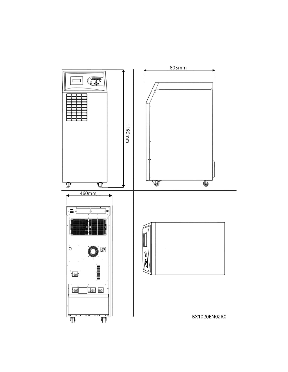
Dimensions (W x D x H)mm
460x805x1190mm

BOXER SERIES 10-20 KVA GUARANTEE
AG-SD-109 Publishing Date: 13.10.2015 Revision No: 0 Rev. Date:
7 CONTACT INFORMATION
www.makelsan.com.tr
Headquarter: İstanbul Deri Organize Sanayi Bölgesi 2. Yol I -5 Parsel 34956 Tuzla/ İstanbul
Tel : 0216 428 65 80
Fax : 0216 327 51 64
E-mail : makelsan@makelsan.com.tr
İzmir Office : Halkapınar Mah. 1348 Sok. 2AE Keremoğlu İş Merkezi Yenişehir – İzmir
Tel : 0232 469 47 00
Fax : 0232 449 47 00
E-mail : izmir@makelsan.com.tr
Ankara Office : Mustafa Kemal Mah. 2157 Sok. No:4/6 Çankaya-Ankara
Tel : 0312 219 82 35/37
Fax : 0312 219 82 36
E-mail : ankara@makelsan.com.tr

AG-SD-109 Publishing Date: 13.10.2015 Revision No: 0 Rev. Date:
www.makelsan.com.tr
Headquarter: İstanbul Deri Organize Sanayi Bölgesi 2. Yol I -5 Parsel 34956 Tuzla/ İstanbul
Tel : 0216 428 65 80
Fax : 0216 327 51 64
E-mail : makelsan@makelsan.com.tr
İzmir Office : Halkapınar Mah. 1348 Sok. 2AE Keremoğlu İş Merkezi Yenişehir – İzmir
Tel : 0232 469 47 00
Fax : 0232 449 47 00
E-mail : izmir@makelsan.com.tr
Ankara Office : Mustafa Kemal Mah. 2157 Sok. No:4/6 Çankaya-Ankara
Tel : 0312 219 82 35/37
Fax : 0312 219 82 36
E-mail : ankara@makelsan.com.tr
 Loading...