

MAKELSAN BOXER BX3310, BOXER BX3330, BOXER BX3315, BOXER BX3320, BOXER BX3340 User Manual
...
USER MANUAL
BOXER SERIES
10 - 20 KVA

USER MANUAL
BOXER SERIES
10 - 20 KVA
AG–SD-109
Rev:0
AG-SD-109 Publishing Date: 13.10.2015 Revision No: 0 Rev. Date:
About The Manual
This manual is prepared for the users of Boxer 10-20 kVA.
Companion Manuals
For further information about this device and its options, please visit www.makelsan.com.tr
Updates
Please visit www.makelsan.com.tr for updates. Always use the latest manuals.
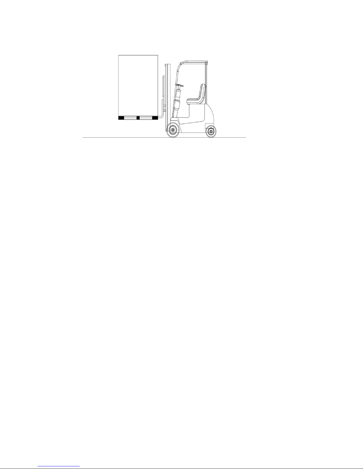
Shipment
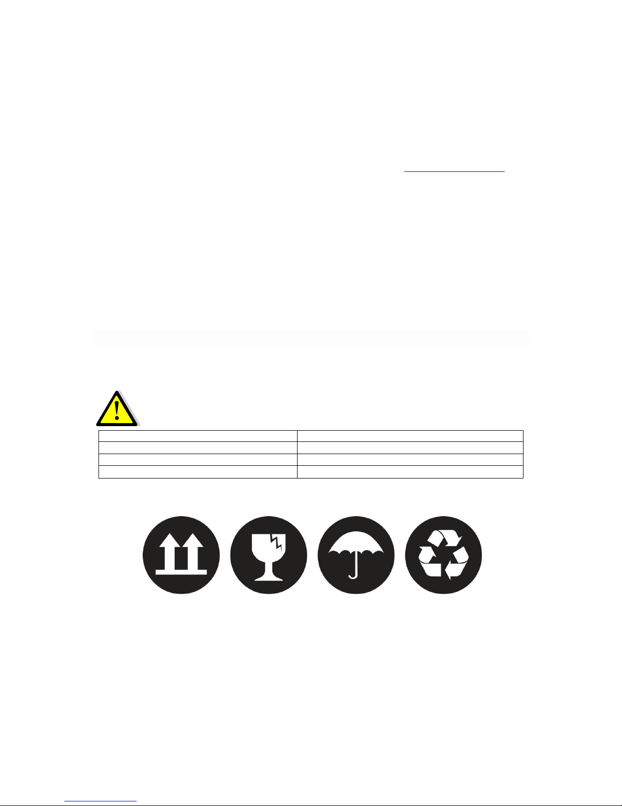
Carrying vehicles or handling accessories must have enough features and characteristics to carry
UPS’s weight.
DO NOT LIFT HEAVY DUTY WEIGHT WITHOUT HELP
1 Person
<18 kg (<40 lb)
2 People
18-32 kg (40-70 lb)
3 People
32-55 kg (70-120 lb)
Carrying vehicles or handling accessories
>55 kg (>120 lb)
Be more careful of sudden movements, especially when batteries are inside of cabinet.

BOXER SERIES 10-20 KVA CONTENTS
AG-SD-109 Publishing Date: 13.10.2015 Revision No: 0 Rev. Date:
CONTENTS
1 SAFETY and WARNINGS ......................................................................................................................................... 1
1.1 Warnings .................................................................................................................................................................... 1
1.2 Clearance and Access ............................................................................................................................................ 2
1.3 Storage ........................................................................................................................................................................ 2
1.4 Shipment .................................................................................................................................................................... 2
2 PRODUCT DESCRIPTION ............................................................................................................................................. 4
2.1 General Information .............................................................................................................................................. 9
2.1.1 Static Transfer Switch .................................................................................................................................. 9
2.1.2 Battery Temperature Regulation .......................................................................................................... 10
2.2 UPS’s Operation Modes ..................................................................................................................................... 10
2.2.1 Normal (Online) Mode .............................................................................................................................. 10
2.2.2 Battery (Stored) Mode .............................................................................................................................. 10
2.2.3 Bypass Mode ................................................................................................................................................. 10
2.2.4 Automatic Restart Mode ........................................................................................................................... 11
2.2.5 Maintenance Mode ..................................................................................................................................... 11
2.3 Battery Management ......................................................................................................................................... 11
2.3.1 Advanced Level Functions (Automatic Battery Test) .................................................................. 12
2.4 User Panel ............................................................................................................................................................... 13
2.4.1 Opening Screen ............................................................................................................................................ 15
2.4.2 Main Menu ...................................................................................................................................................... 15
2.4.3 Navigating Through the Menus ............................................................................................................. 15
2.4.4 Password Protected Menus .................................................................................................................... 16
2.4.5 Control Menu ................................................................................................................................................ 16
2.4.6 Status Menu ................................................................................................................................................... 16
2.4.7 Setup Menu .................................................................................................................................................... 17
2.4.8 Logging Menu ................................................................................................................................................ 20
3 INSTALLATION ............................................................................................................................................................. 21
3.1 Single Module Installation ............................................................................................................................... 21
3.1.1 Warnings ......................................................................................................................................................... 21
3.1.2 Pre-Installation Check Up ........................................................................................................................ 22
3.1.3 Positioning ..................................................................................................................................................... 22
3.1.3.1 Positioning the UPS ............................................................................................................................ 22
3.1.3.2 Configuration of Internal Batteries .............................................................................................. 23

BOXER SERIES 10-20 KVA CONTENTS
AG-SD-109 Publishing Date: 13.10.2015 Revision No: 0 Rev. Date:
3.1.3.3 Placing External Batteries ............................................................................................................... 24
3.1.4 Transportation Type of Cabinets .......................................................................................................... 26
3.1.5 Mains, Load and Battery Connections ................................................................................................ 26
3.1.5.1 External Protections .......................................................................................................................... 26
3.1.5.2 Cable and Fuse Configuration ........................................................................................................ 27
3.1.5.3 Cable Connections ............................................................................................................................... 27
3.1.5.4 Connecting Batteries .......................................................................................................................... 31
3.1.5.4.1 Internal Battery Installation Procedure and Connection ........................................... 31
3.1.5.4.2 External Battery Installation Procedure and Connection .......................................... 32
3.1.5.5 Control and Communication Cable Connections .................................................................... 34
3.2 Parallel Setup ........................................................................................................................................................ 35
4 OPERATION ................................................................................................................................................................... 39
4.1 Operation Procedure ......................................................................................................................................... 39
4.1.1 Circuit Breakers ........................................................................................................................................... 39
4.1.2 First Start-Up................................................................................................................................................. 39
4.1.3 Testing the Operation Modes of the UPS ........................................................................................... 41
4.1.3.1 Switching from Normal Mode to Battery Mode ...................................................................... 41
4.1.3.2 Switching from Normal Mode to Static Bypass Mode .......................................................... 41
4.1.3.3 Switching from Static Bypass Mode to Normal Mode .......................................................... 42
4.1.3.4 Switching from Normal Mode to Maintenance Bypass Mode ........................................... 42
4.1.4 Performing a Complete Shutdown ....................................................................................................... 44
4.1.5 EPO (Emergency Power OFF) ................................................................................................................ 45
4.1.6 RS232 Serial Communication Installation and Examination .................................................... 45
5 EXPLANATIONS of LOGGING .................................................................................................................................. 46
6 TABLE of TECHNICAL SPECIFICATIONS ........................................................................................................... 52
7 CONTACT INFORMATION ........................................................................................................................................ 54
BOXER SERIES 10-20 KVA SAFETY AND WARNINGS
AG-SD-109 Publishing Date: 13.10.2015 Revision No: 0 Rev. Date:
1 SAFETY and WARNINGS
1.1 Warnings
This manual must definitely be read and understood before installing the UPS. The installation
and first start-up can be performed only by an authorized MAKELSAN staff.
Installation and start-up by unauthorized persons may cause serious injury and/or result in
death.
The UPS is designed to be used in continuous vertical position in fixed-positioned applications.
THE UPS MUST BE USED WITH GROUND CONNECTION.
Connect the ground cable before connecting the mains.
The ground leakage current may rise up to 0,4A.
THE UPS MUST BE DISCONNECTED FROM THE MAINS AND BATTERIES
BEFORE SERVICING. ALSO WAIT FOR AT LEAST 5 MINUTES FOR THE DC BUS
CAPACITORS TO DISCHARGE AFTER POWER OFF.
Service-Maintenance
All service and maintenance operations are performed internally. All parts of UPS can be
serviced and replaced only by a trained personnel.
Performing regular protective maintenance at least once a year is
recommended beginning from the first installation. (This service will be
provided for a fee by authorized MAKELSAN staff.)
BATTERY VOLTAGE MAY RISE UP TO 450 VDC!
Battery voltages are in deadly levels (450Vdc). Batteries must not be touched except the trained
staff.
Batteries certainly must not be thrown into fire. Regarding the topic of batteries which are dead
and defected: The waste batteries must definitely not be thrown to nature. They must be
delivered to MAKELSAN authorized technicians or to the foundations which are authorized for
collecting waste batteries by the Ministry of Environment.
Fire extinguishing equipment must be kept nearby the UPS.
BOXER SERIES 10-20 KVA SAFETY AND WARNINGS
AG-SD-109 Publishing Date: 13.10.2015 Revision No: 0 Rev. Date:
1.2 Clearance and Access
Clearance
There exist no air inlet or outlet grilles on the sides of 10-20 kVA UPS. All air is taken through
front and evacuated through fan grids on the back side. There must be 1 m clearance at least at
front side and 1.2 m clearance at least at rear side of UPS. There should not be permanent or
temporary use within the limits specified. Otherwise, the UPS’s performance will decrease.
Access
Operator can reach the inside of UPS through front panel on our products in the range of 10-20
kVA.Therefore, enough area must be left for operator. Furthermore, the device can be accessed
through the back side for service and maintenance. Thus, sufficient area must always be left in
the back side in order that service staff can work.
1.3 Storage
UPS should be kept in a room or area where is protected from excessive moisture and heat
before commissioning.
Unused batteries must be charged at regular intervals. This time interval is
determined by the battery supplier. Charging batteries can be performed
periodically by connecting to a proper mains for a while.
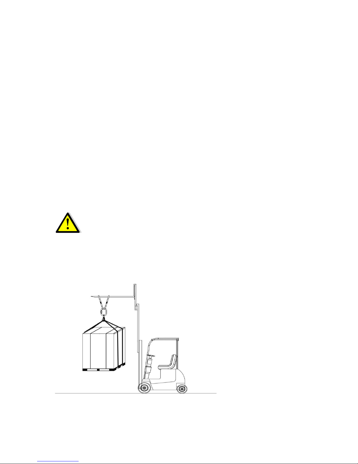
1.4 Shipment
Carrying vehicles or handling accessories must have enough features and characteristics to carry
UPS’s weight.
BOXER SERIES 10-20 KVA SAFETY AND WARNINGS
AG-SD-109 Publishing Date: 13.10.2015 Revision No: 0 Rev. Date:
The cabinet is equipped with four wheels. By this means, it can be easily moved and placed.
These wheels must only be used on smooth surfaces.
After the UPS has been placed on an appropriate position, front wheels must be locked. Back
wheels are fixed. Be more careful of sudden movements, especially when batteries are inside of
cabinet.
Move the UPS as rarely as possible.
BOXER SERIES 10-20 KVA PRODUCT DESCRIPTION
AG-SD-109 Publishing Date: 13.10.2015 Revision No: 0 Rev. Date:
2 PRODUCT DESCRIPTION
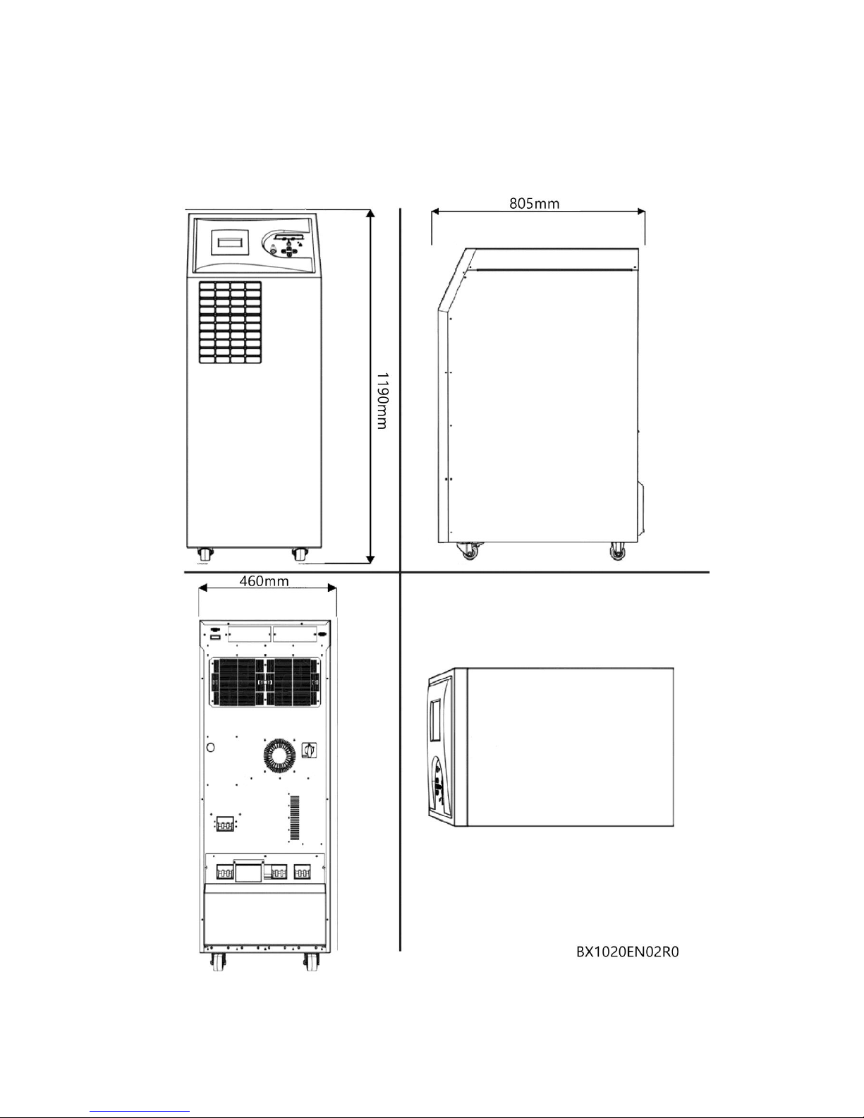
General View
BOXER SERIES 10-20 KVA PRODUCT DESCRIPTION
AG-SD-109 Publishing Date: 13.10.2015 Revision No: 0 Rev. Date:
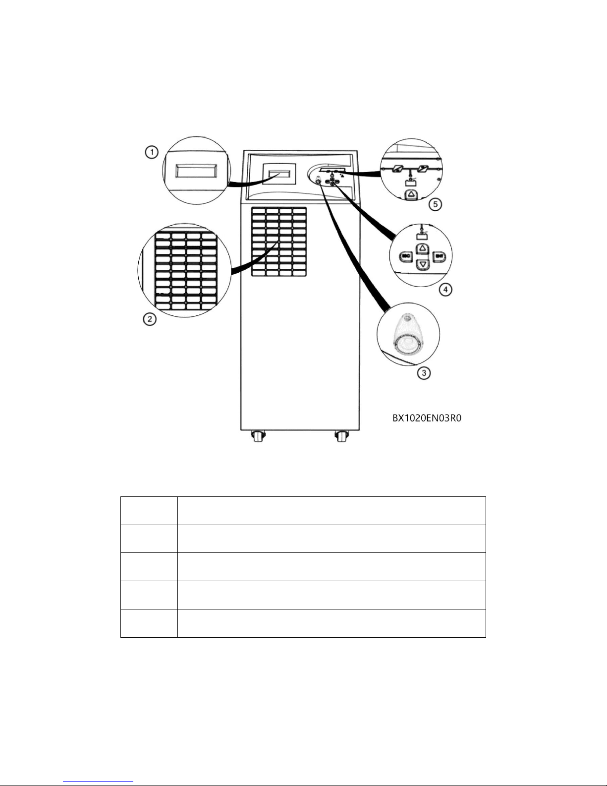
Front View
1
LCD Display
2
Fresh Air Vacuum Grid
3
EPO (Emergency Power Off) Button
4
Menu Navigation Keys
5
Mimic Diagram
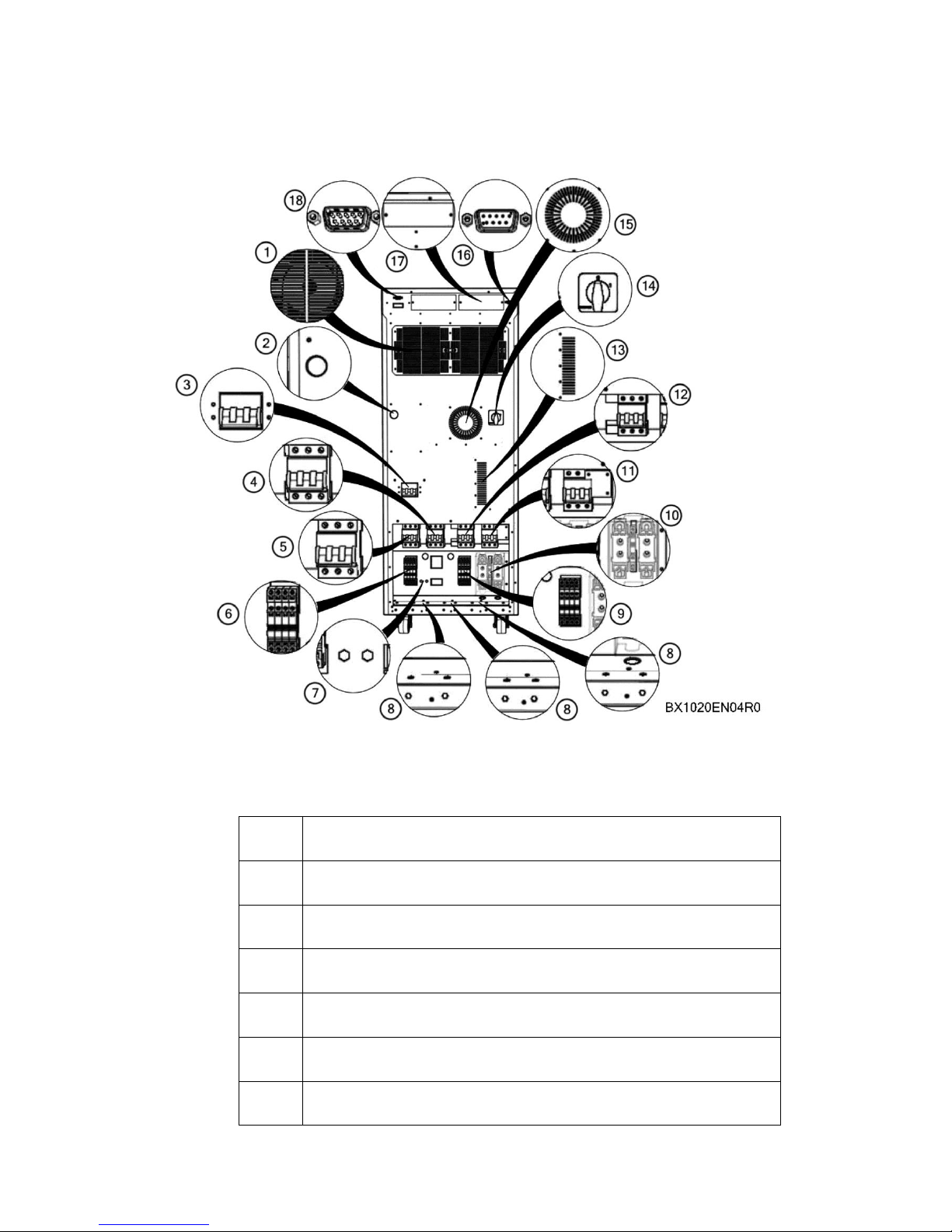
Back View
BOXER SERIES 10-20 KVA PRODUCT DESCRIPTION
AG-SD-109 Publishing Date: 13.10.2015 Revision No: 0 Rev. Date:
1
Rectifier/Charger-Inverter Cooling Fans
2
Bus Bar Charging Button
3
Optional External Bypass Switch
4
Maintenance Bypass Switch
5
Mains Switch
6
Mains Connecting Terminal
7
Ground Connection

BOXER SERIES 10-20 KVA PRODUCT DESCRIPTION
AG-SD-109 Publishing Date: 13.10.2015 Revision No: 0 Rev. Date:
8
Input-Output-Battery Cable Fixing Connectors
9
Output Connecting Terminal
10
Battery Fast Circuit Breakers and Connecting Terminals
11
Battery Commissioning Switch
12
Output Switch
13
Thyristor Hot Air Evacuation Channel
14
Optional Cold Start(Starting through battery) Switch
15
Winding Hot Air Evacuation Channel
16
RS232 Terminal for Communication Software
17
Optional Card Slots
18
Optional Parallel Connection Terminal
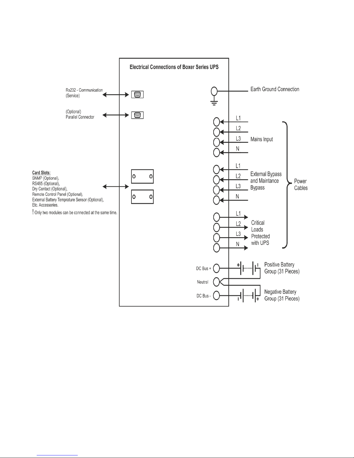
Electrical Connections
BOXER SERIES 10-20 KVA PRODUCT DESCRIPTION
AG-SD-109 Publishing Date: 13.10.2015 Revision No: 0 Rev. Date:
BOXER SERIES 10-20 KVA PRODUCT DESCRIPTION
AG-SD-109 Publishing Date: 13.10.2015 Revision No: 0 Rev. Date:
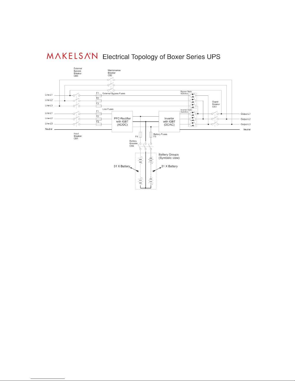
2.1 General Information
General operation topology of Boxer Series UPS can be recognized as follows:
The UPS is connected to the mains voltage through the CB1 breaker. After this energy has filled
DC bus condensers, the rectifier operates. The rectifier converts the AC mains energy to DC
voltage and charges the batteries in a controlled manner. When there exists no mains, sufficient
level DC bus voltage is created, using battery voltage. DC bus voltage is converted to mains
synchronized AC voltage by the inverter. This is a high quality voltage. Generated AC power are
applied to the loads through the static semi-conductor transfer switches and output (load)
circuit breakers.
When maintenance or repair are needed, before input(CB1) and output (CB3)circuit breakers
are switched to open circuit (OFF), switch the UPS from normal mode to static bypass mode(see
4.1.3.2). Afterwards, the maintenance circuit breaker (CB2) is switched to closed circuit (ON).
After that, output (CB3) and input (CB1) circuit breakers of the UPS are taken to the off position
respectively.
2.1.1 Static Transfer Switch
Some blocks are named as static switches as can be seen above. These blocks consist of inverse
parallel connected thyristors. These switches, which are under the control of the mainboard
control unit, provides controlling of feeding the loads through either mains or inverters. The
loads are fed through inverter during the normal operating mode. Therefore, inverter static
switches are active if there is no problem with the system.
System provides the loads to be fed smooth and seamless by mains or inverter. In order to
manage this process at minimum risk, UPS synchronizes the inverter output and mains bypass

BOXER SERIES 10-20 KVA PRODUCT DESCRIPTION
AG-SD-109 Publishing Date: 13.10.2015 Revision No: 0 Rev. Date:
as the same phase and frequency. Therefore, inverter frequency is the same as mains frequency
as long as it is acceptable within frequency limit.
User can switch between mains and inverter, using the front panel. Loads, operating from the
mains with user instruction, will automatically undertake the load in the event that the mains
cuts off or is out of tolerance.
2.1.2 Battery Temperature Regulation
Our products, in the range of 10-20 kVA, have spaces to place internal battery in their cabinets.
There exists temperature sensor in external battery cabinets. Temperature of these batteries is
measured by this “temperature sensor”. The UPS adjusts battery charge parameters according to
the information of the detected temperature. These parameters can easily be adjusted via LCD in
the system or TELNET interface by authorized staff.
This sensor and the UPS regulates charge parameters in the same way. In this case, we advise
you to order “External Battery Temperature Sensor Kit” for temperature detection of the
UPS.
2.2 UPS’s Operation Modes
Boxer SERIES UPS's on-line and has a double loop structure. Our products operate in the
following modes:
Normal (Online) Mode
Battery Mode
Bypass Mode
Auto Restart Mode
Maintenance Mode
2.2.1 Normal (Online) Mode
In this mode, UPS supplies the load through the inverters. Rectifier unit is fed by the AC mains.
Inverter and battery charger units can be fed by the generated DC supply.
2.2.2 Battery (Stored) Mode
Due to any failure of the mains, while the UPS feeds the critical loads through inverter, this
energy can be supplied from the batteries.
2.2.3 Bypass Mode
On account of UPS overload or any problem on inverter, no qualified AC output is produced and
if bypass voltage and frequency are in tolerance, loads are then fed trough bypass source. UPS
switches from inverter to AC source via static transfer switches without any interruption. The
inverter source and mains must be synchronized in order to manage this switching processes

BOXER SERIES 10-20 KVA PRODUCT DESCRIPTION
AG-SD-109 Publishing Date: 13.10.2015 Revision No: 0 Rev. Date:
without any problem. If inverter output and mains are not synchronized, this switching may take
up to 15 msec. varying according to load type.
2.2.4 Automatic Restart Mode
In case of any failure of the mains, the UPS will continue feeding the critical loads until the
batteries reaches the end of discharge voltage level. The UPS will go on working until the
batteries are drained, and then will shut down. After the mains conditions gets back to normal,
the UPS automatically starts to operate in a period to be determined. In this case, the UPS
continues to operate in normal mode as long as the mains values are in desired criteria. In the
Boxer SERIES UPS, this feature is not activated in factory settings.
2.2.5 Maintenance Mode
The UPS is equipped with a specific protection switch in order to keep the loads powered during
maintenance. This switch is designed so as to handle UPS loads completely.
2.3 Battery Management
Constant Charge Current
Constant current as 1/10 rate of the battery capacity is applied to battery, until the battery
reaches the float charge voltage.
Float Charge
Depending on the battery discharge current, 1/3 of the energy of the battery is charged at this
level. Owing to this level, batteries are kept ready for use at the highest capacity. For lead-acid
batteries, this voltage varies between the values of 2.2-2.35 V/cell. This voltage may differ
slightly due to temperature adaptation. Option of setting this coefficient is provided with our
UPS. If the temperature sensor is used, it is recommended to use.
Deep Discharge Protection
While the system is operating in the battery mode, if battery voltage has dropped below the
deep discharge voltage level, the UPS shuts down and stops absorbing energy from the batteries.
This value varies between 1.6-1.75 V/cell for Lead-Acid batteries, and between 0.9-1.1 V / cell
for Ni-Cd batteries.
Low Battery Warning Level
While the system operates in spare, in other words, battery mode, if the battery capacity drops
below its 40% value with actual loads, it will give audible and visible alarms. This value can be
adjusted by user between 20%-70%.

BOXER SERIES 10-20 KVA PRODUCT DESCRIPTION
AG-SD-109 Publishing Date: 13.10.2015 Revision No: 0 Rev. Date:
2.3.1 Advanced Level Functions (Automatic Battery Test)
The auto battery test automatically discharges 10% of the battery existing capacity in a certain
period defined (default is 90 days). The period between two tests can be adjusted by user
between 30-360 days. At the end of the test, one of these two status, “good or replace” is
determined.
At the end of this test, if batteries are reported as “replace”, then the
batteries are completely drained after the test. In this case, loads can
remain unpowered in case of mains power off.
This test can automatically be started by command from front panel monitor, via telnet interface,
via RS232 smart communication or via UPSMAN (SNMP, see the options).
As a result of all these tests, it is checked whether the batteries that are presently used can
supply the minimum needs of loads in case of the first power-off or not. It is recommended that
test results be checked at regular intervals.
BOXER SERIES 10-20 KVA PRODUCT DESCRIPTION
AG-SD-109 Publishing Date: 13.10.2015 Revision No: 0 Rev. Date:
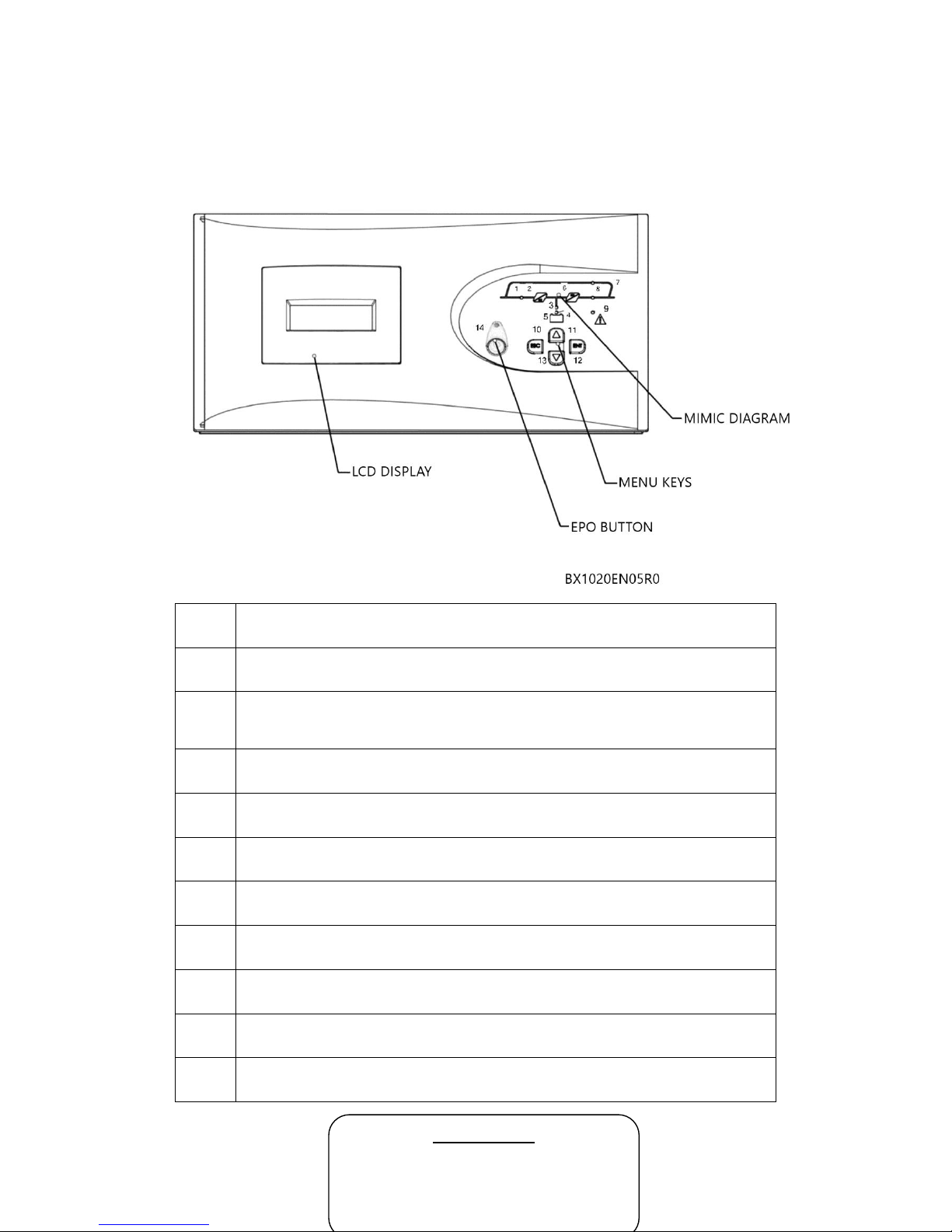
2.4 User Panel
User panel consists of mimic diagram, LCD screen, EPO button and menu keys. The UPS can be
controlled via this panel.
1
Rectifier indicator LED
It constantly illuminates when rectifier works.
2
AC/DC module (Rectifier)
3
Battery discharge indicator LED
It illuminates in battery mode and flashes when UPS is started up through
batteries.
4
Battery charge indicator LED
It illuminates while the batteries are charged.
5
Battery module
6
DC/AC module (Inverter)
7
Bypass static switch indicator LED
It illuminates while the loads are fed through bypass line.
8
Inverter static switch indicator LED
It illuminates when the load is fed by the inverter.
9
Alarm/Warning indicator LED
10-13
Menu keys
14
EPO Button
MAIN SCREEN
Manufacturer –Device Name
Battery Charge Status as Percentage
Load Status as Percentage
Period of Working from Battery
 Loading...