

MAKELSAN POWERPACK PLUS SERIES, 1KVAS, 2KVAH, 1KVAH, 3KVAS User Manual
...
POWERPACK PLUS SERIES
1-2-3 kVA
UNINTERRUPTIBLE POWER SUPPLIES
USER M ANU A L
ONL INE U P S
s
www. makelsan .com.tr

Foreword
Manual instruction
Thanks for purchasing our UPS, it is safe and reliable, so few maintenance is required.
Read this manual carefully and completely. It includes instructions of safety installation
and operation. They will help your UPS obtain the longest life and service. This manual
accounts the internal working principle and the relative protection functions. This manual
also contains information about the usage of the equipment.
Please obey the instructions and all the warning stated in the manual or on the machine.
Don’t operate the machine before finishing reading the safety and operation instructions.
Note: Because of the continuous improvements, our products may differ somewhat from the
contents included in this manual. You can contact local office to get the information when
necessary.

Content
1.Safety instruction .......................................................................................................... 1
1.1 Safety instruction ................................................................................................... 1
1.2 Symbols indication ................................................................................................ 1
2.Product Introduction ...................................................................................................... 3
2.1 The appearance of the product ............................................................................. 3
2.2 The principle of the product ................................................................................... 4
2.3 Model .................................................................................................................... 4
3.Installation ..................................................................................................................... 5
3.1 Unpacking and inspection ..................................................................................... 5
3.2 Notes ..................................................................................................................... 5
3.3 UPS input connection ............................................................................................ 5
3.4 UPS output connection ......................................................................................... 6
3.5 Long backup external battery connection .............................................................. 6
4.Panel display, operation and running ............................................................................ 8
4.1 Faceplate display illumination ............................................................................... 8
4.2 Operation ............................................................................................................ 11
4.3 Parameter setting ................................................................................................ 12
4.4 Parameters inquiring ........................................................................................... 20
4.5 Run mode ........................................................................................................... 22
5.Maintenance ............................................................................................................... 25
6.Troubleshooting and performance of product ............................................................. 26
6.1 LED indication and warning table ........................................................................ 26
6.2 Troubleshooting .................................................................................................. 28
6.3 EMC standard/Safety standard ........................................................................... 29
6.4 Product Performance .......................................................................................... 29
6.5 Communication interface .................................................................................... 30

1. Safety instruction
Abstract
This chapter mainly introduce the safety marks and notes of 1KVA-3KVA series on-line
UPS. Read this chapter carefully before operating on the equipment.
1.1 Safety instruction
There is dangerous voltage and high temperature inside the UPS. During the
installation, operation and maintenance, please abide the local safety instructions and
relative laws, otherwise it will result in personnel injury or equipment damage. Safety
instructions in this manual act as a supplementary for the local safety instructions.
Our company will not assume the liability that caused by disobey of safety instructions.
Please note the following:
1. Don’t use the UPS when the actual load exceeds the rated load.
2. There are high-capacity batteries in the standard type UPS. You mustn’t open the
enclosure or it will lead to electric shock. If it needs internal maintenance or battery
replacement, please send it to the designated site.
3. Internal short-circuit of the UPS will cause electric shock or fire. So don’t place the
containers equipped with liquid on the top of the UPS so as not to cause danger of
electric shock and so on.
4. Don’t put the UPS in a place with high temperature or humidity as well as the
corrosive gas, much dust.
5. Keep good air circulation between in-vent on front panel and out-vent on back
panel.
6. Avoid direct sunlight or near heat-dispensed objects.
7. In case that the smoke appears on the UPS, please cut off the power as soon as
possible and contact the dealer service site.
1.2 Symbols indication
The safety symbols cited in this manual are shown in table 1-1, which are used to
inform readers of safety issues that should be obeyed when installation, operation and
maintenance.
1
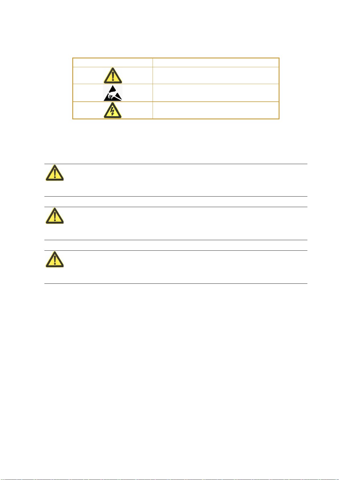
Safety Symbol Indication
Attention
Static discharge sensitive
Electric shock
There are three levers of safety grade: Dangerous, Warning and Attention. The remark
is on the right side of the safety symbol, the detailed comments is behind, shown as
following:
Dangerous
Indicate risk of serious injury or death or seriously damage the equipment
Warning:
Indicate risk of serious injury or damage the equipment.
Attention:
Indicate risk of injury or damage the equipment.
2
2. Product Introduction
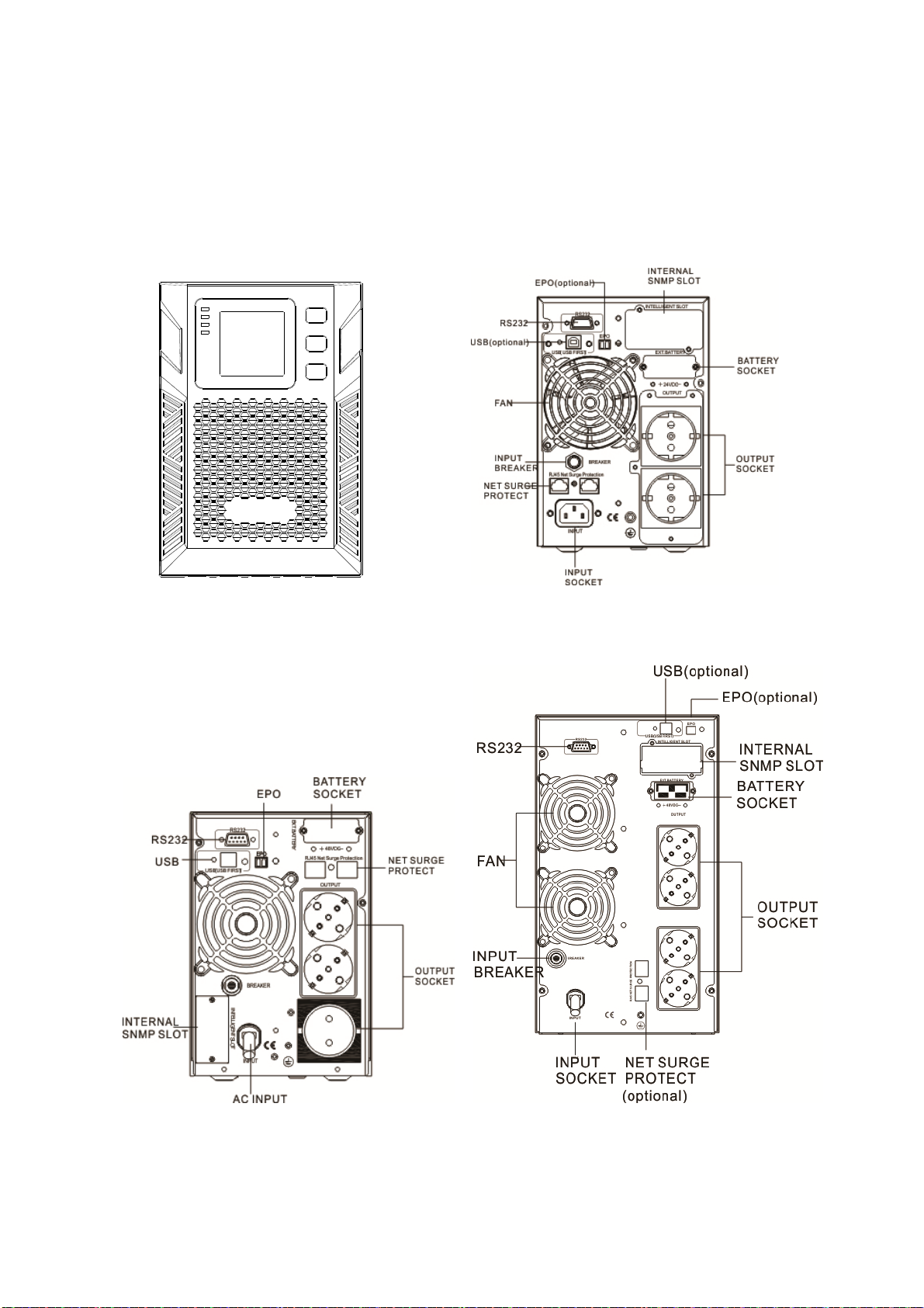
2.1 The appearance of the product
FIG.1 Front Panel view
FIG.2 1kVA Rear Panel view
3
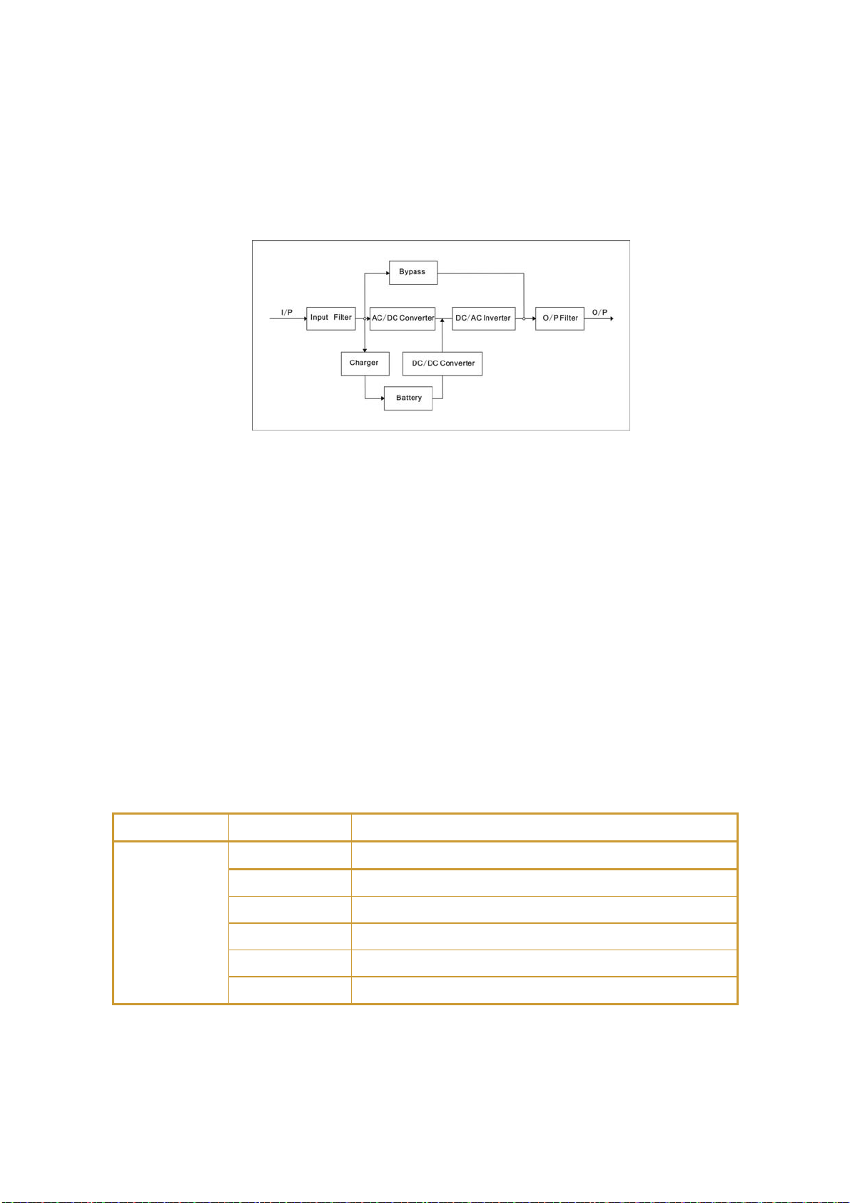
FIG.3 2/3kVA Rear Panel view
2.2 The principle of the product
FIG.4 UPS Principle Diagram
1.Input filter: Complete filtering the input AC utility power to provide the clean power
for UPS.
2. AC/DC converter: Convert the filtered AC mains to DC and boost the DC for DC/AC
inverter.
3. DC/DC booster: When the UPS works in battery mode, the circuit boosts the DC for
DC/AC inverter.
4. DC/AC inverter: Convert the boosted DC to stable AC output.
5. Bypass: When overload or failure of inverting happen in the UPS, it transfers to
bypass mode to supply power to loads.
6. Charger: Standard unit provides 1A.
7. Battery: Sealed Lead Acid Battery.
8. Output filter: Complete filtering the output of the UPS to provide the clean power for
loads.
2.3 Model
UPS sort MODEL NO Remark
1KVAS Internal 1A charger, 2 PCS 9AH batteries
1KVAH Internal 6A charger, 2 PCS batteries
Standard
unit
2KVAS Internal 1A charger, 4 PCS 9AH batteries
2KVAH Internal 6A charger, 4 PCS batteries
3KVAS Internal 1A charger, 6 PCS 9AH batteries
3KVAH Internal 6 charger, 6 PCS batteries
4

3. Installation
3.1 Unpacking and inspection
1. Unpacking the UPS and check that whether it’s damaged during the
transportation. If damaged or some parts missing, don’t start the
machine and inform the carrier and franchiser.
2. Check the annex (please consult Appendix Table 1).
3. Check if the equipment is just what you wanted to purchase. You can affirm through
inspecting the model number on back panel of the equipment.
3.2 Notes
1. Please place the UPS in a clean, stable environment, avoid the vibration, dust, too
humidity, flammable gas and liquid, corrosive.
2. The ambient temperature around UPS should keep in a range of 0℃~40℃. If UPS
works above 40℃, it is required that the rated value of the largest load decreases
12% while the temperature increases every 5℃ . The highest temperature cannot
be more than 50℃ when UPS works.
3. UPS should be placed in a sufficiently ventilated place.
3.3 UPS input connection
Connect the UPS to the mains by input power cable which is equipped
with the UPS.
5
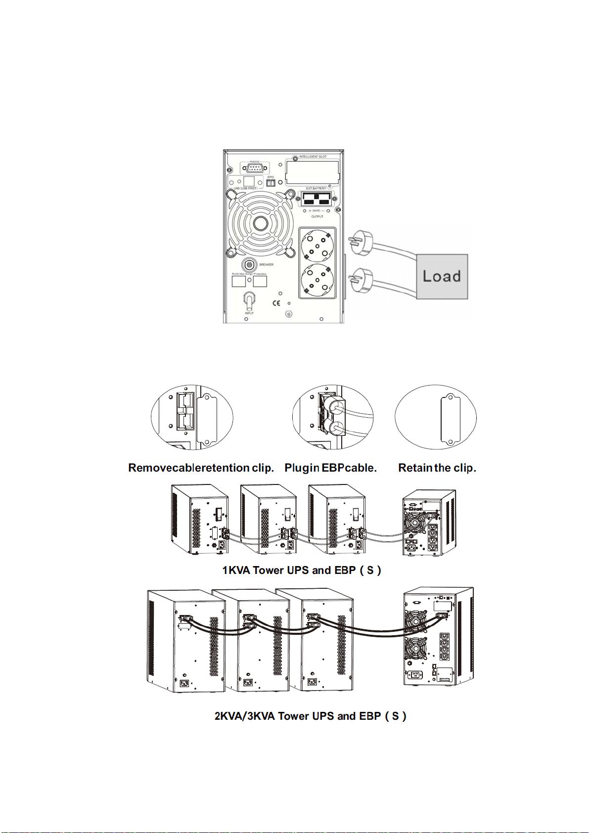
FIG.5 Input Connection
3.4 UPS output connection
FIG.6 Output connection
3.5 To install the optional EBP(s) for a UPS(Standard unit):
6
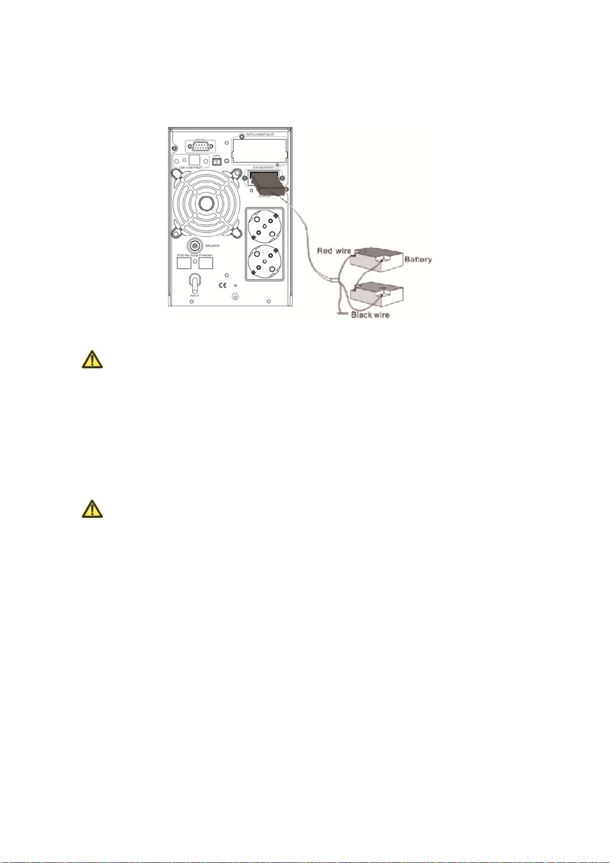
3.6 Long backup external battery connection
FIG.7 battery connection
Warning:
★
Before installing battery, make sure that UPS and breaker are all turned off. Remove
all your metallic adornment such as finger ring, watch, and so on before connecting
battery.
★
No anti-connection or short circuit between the battery anode and cathode forever.
Red cable connect with battery anode “+” and black cable connect with cathode “-”.
★
Please use the screwdriver with insulating handle. Do not lay the tools or metallic
goods on the battery.
Notice:
★
When using the external battery, It is best to use external battery cable which
matches with the equipment.
★
When connecting load to UPS, first turn off load and then connect the power cable
and finally turn on load one-by-one.
★
Inductance loads such as motor, fluorescent lamp, photocopier are strictly prohibited
connecting to UPS to avoid damage.
★
Plug UPS on the special socket with over-current protection, the power socket that
used should be connected with ground wire.
★
UPS is likely to have output voltage no matter whether the power input cable is
plugged in mains input socket. If you wish UPS have no output, first break off the
switch and then cancel the mains.
★
When connect laser printer, select the capacity of UPS according to the UPS start
power because the startup power is higher.
7
4. Panel display, operation and running
The operation is simple, operators only need to read the manual and
follow the operation instructions listed in this manual without any special training.
4.1 Faceplate display illumination
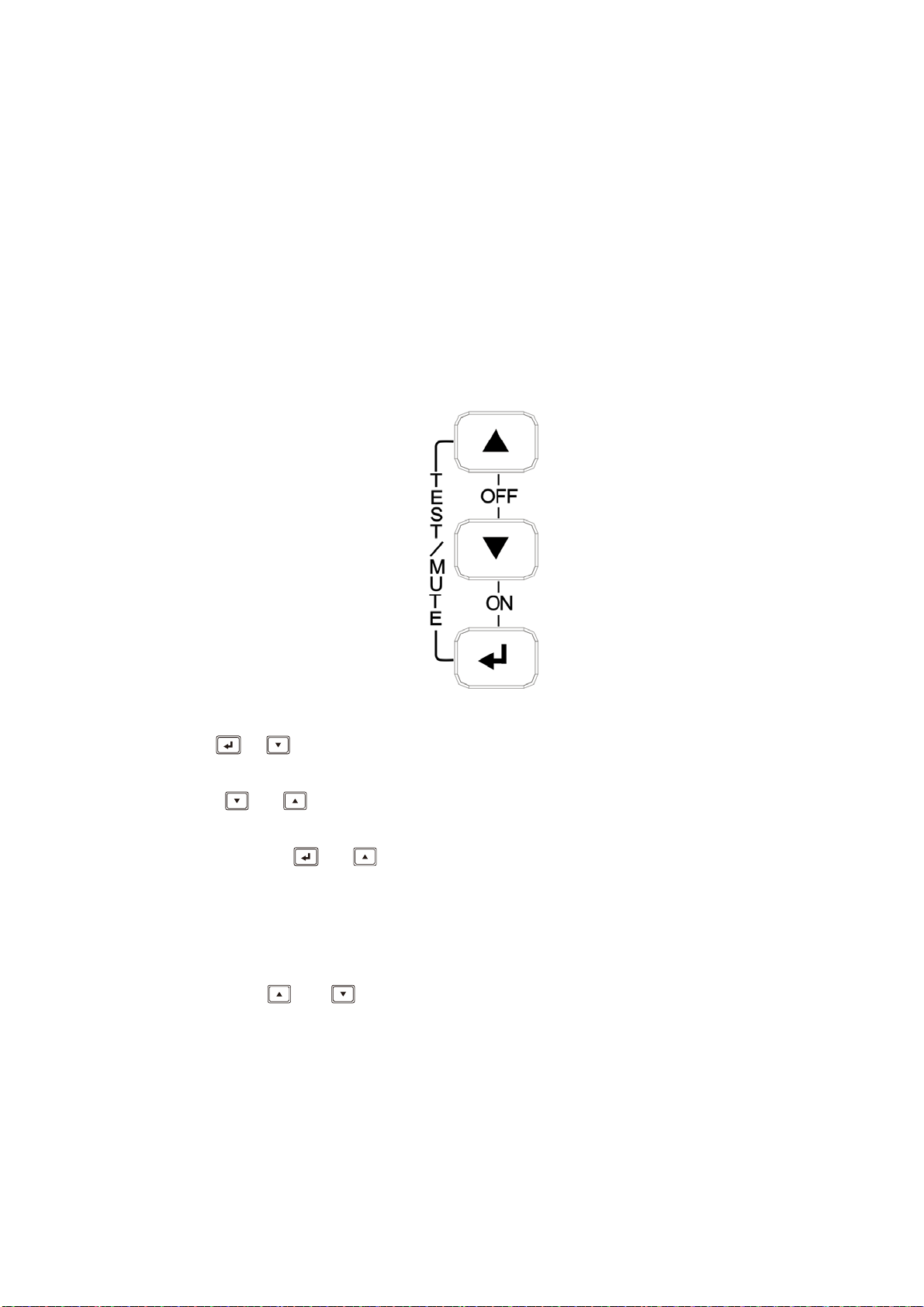
4.1.1 Keys function
FIG.8 front panel buttons instruction
ON key ( + )
Press and hold this key for more than half a second to turn on the UPS.
OFF key (
Press and hold this key for more than half a second to turn off the UPS.
TEST/MUTE key (
Press and hold the key for more than 1 second in Line mode or economical mode:
UPS runs the self-test function.
Press and hold the key for more than 1 second in battery mode: UPS runs the mute
function.
INQUIRING key or
Non-function setting mode:
Press and hold the key for more than half a second (less than 2 seconds): Indicate the
items of the LCD item section orderly.
+ )
+ )
8
Press and hold this key for more than 2 seconds: Circularly and orderly display the
items every 2 seconds, when press and hold the key for some time again, it will turn to
output status.
Function setting mode:
Press and hold the key for more than half a second (less than 2 seconds): Select the
set option.
Function setting key
Non-function setting mode:
Press and hold the key for more than 2 seconds: Function setting interface.
Function setting mode:
Press and hold the key for more than half a second (less than 2 seconds): Affirm the
set option.
Press and hold the key for more than 2 seconds, exit from this function setting
interface.
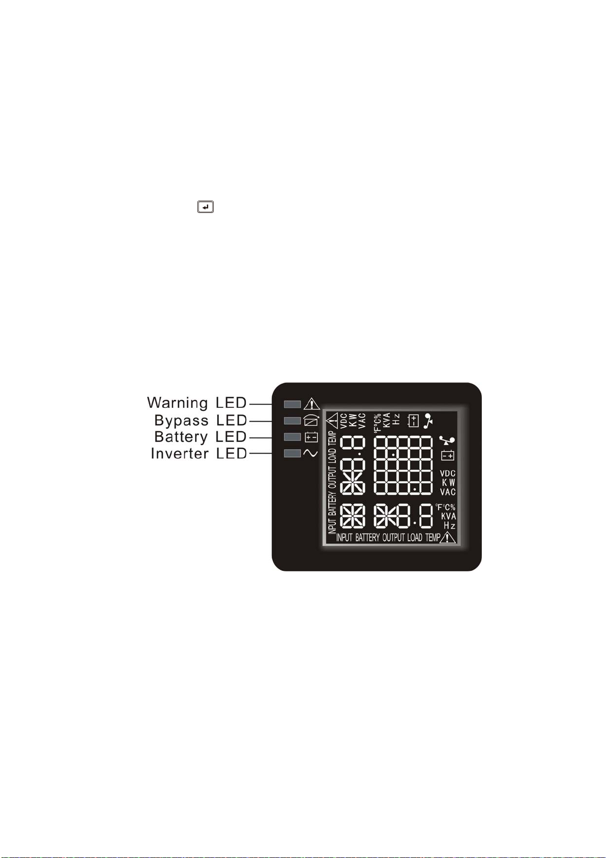
4.1.2 The function of LED indicators
Warning red LED is on: UPS is fault. For example: Overload beyond the allowed time,
inverter fault, BUS fault, over temperature fault etc.
Bypass yellow LED is on: UPS is alarming. For example: Bypass mode supply power
and etc.
Battery yellow LED is on: UPS is alarming. For example: Battery mode supply power
and etc.
Inverter green LED is on: UPS is normally powered by mains or ECO mode or battery
mode.
After starting the UPS, the four LEDs will light and go out one-by-one. It circulates
several times until starting the UPS successful.
9
 Loading...