

Makel MSA-CM Series User Manual

USER’S
MANUAL
KNX
Switch Actuator
MSAxxyy-CM
Shutter & Blinds Actuator
Device Manipulation & ETS™ Application Description
May, 2015
Revision Sheet
Release No. Date Revision Description
Rev. 0 22/05/2015 User’s Manual Created
Rev. 1 02/06/2015 Added more detailed descriptions to the functionalities
User’s Manual Page 2

USER'S MANUAL
TABLE OF CONTENTS
Page #
1 GENERAL INFORMATION................................................................................................................ 6
1.1 System Overview.............................................................................................................................6
1.2 Acronyms and Abbreviations..........................................................................................................6
2 SYSTEM SUMMARY........................................................................................................................... 8
2.1 Application Functions Overview.................................................................................................... 8
2.2 Application Communication Objects.............................................................................................9
3 GETTING STARTED.......................................................................................................................... 11
3.1 Connecting for the first time.........................................................................................................11
3.2 Downloading application with ETS™..........................................................................................11
4 DETAILED FUNCTIONS DESCRIPTION......................................................................................13
4.1 General Configuration..................................................................................................................13
4.2 Lighting Configurations................................................................................................................15
4.2.1 O[x]: General 15
4.2.2 O[x]: Measurements 25
4.2.3 O[x]: Scenes 26
4.3 Shutter and Blinds.........................................................................................................................28
4.3.1 O[x]-[x+1]: General 29
4.3.2 O[x]-[x+1]: Scenes 34
4.3.3 O[x]-[x+1]: Alarms configurations 36
Appendix A - Logic operations.................................................................................................................40
User’s Manual Page 3

I - AND (Logical Conjunction)...........................................................................................................40
II - OR (Logical Disjunction).............................................................................................................. 41
III - XOR (Exclusive disjunction).......................................................................................................41
IV - NOT (Negation)............................................................................................................................42
Appendix B - KNX Data types..................................................................................................................43
Appendix C - Detailed description of Communication objects................................................................46
I - Lighting........................................................................................................................................... 47
II - Shutter and Blinds.........................................................................................................................48
User’s Manual Page 4

1 GENERAL INFORMATION
User’s Manual Page 5

1 General Information
1 GENERAL INFORMATION
1.1 System Overview
This manual refers to the following devices for KNX bus:
• MSAxxyy-CM: xx Channels, with yy amperes of maximum current rating per channel Switch
Actuator / Shutter & Blinds actuator.
All of the variants of MSAxxyy family includes:
• 1 programming touch button with 1 LED that shows whenever programming mode is active;
• 1 Manual Mode enable/disable touch button with 1 LED that shows whenever Manual Mode is
active or not;
• xx touch buttons that controls each of the xx channels (if Manual Mode active) with xx LEDs
that shows the contact position of each of the channels.
1.2 Acronyms and Abbreviations
CO Communication Object
EIB European Installation Bus (former name to KNX; no longer in use)
GA Group Address
LED Light Emitting Diode
User’s Manual Page 6

2 SYSTEM SUMMARY
User’s Manual Page 7
2 SYSTEM SUMMARY
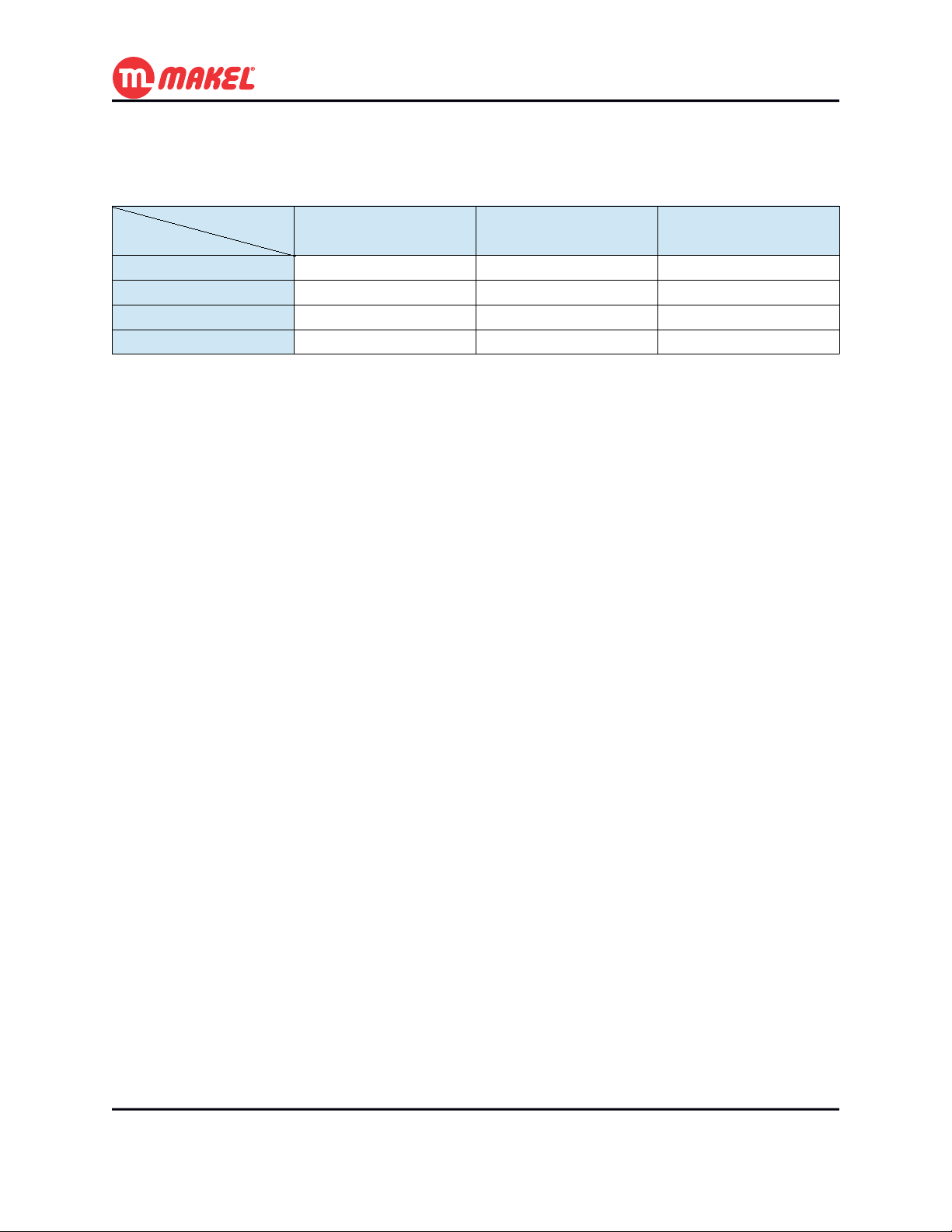
Table 1: Applications specifications
Specs
Variant
MSA04yy-CMA 62 250 250
MSA08yy-CMA 122 250 250
MSA12yy-CMA 182 250 250
MSA16yy-CMA 242 250 250
Number of
Communication Objects
Maximum number of
Group Addresses
Maximum number of
Associations
2.1 Application Functions Overview
The MSAxxyy-CMA ETS™' application provides the interface to individually configure each of the pair
of channels on the products MSAxxyy-CM with one of the following functions:
• Lighting;
• Shutters and Blinds.
Depending on the function set to each channel, the respective possible configurations and possible
available Communication Objects (COs) vary.
When configured to Lighting each of the switches (relays) is one channel, what means that one switch
can preforme the “On” and “Off” operation over a light (or group of lights under the same control).
However, when configured to Shutter and Blinds, in order to control “Up” and “Down” movements it
takes two switches (relays), one the activates the “Up” movement and other that activates the “Down”
movement.
User’s Manual Page 8
2.2 Application Communication Objects
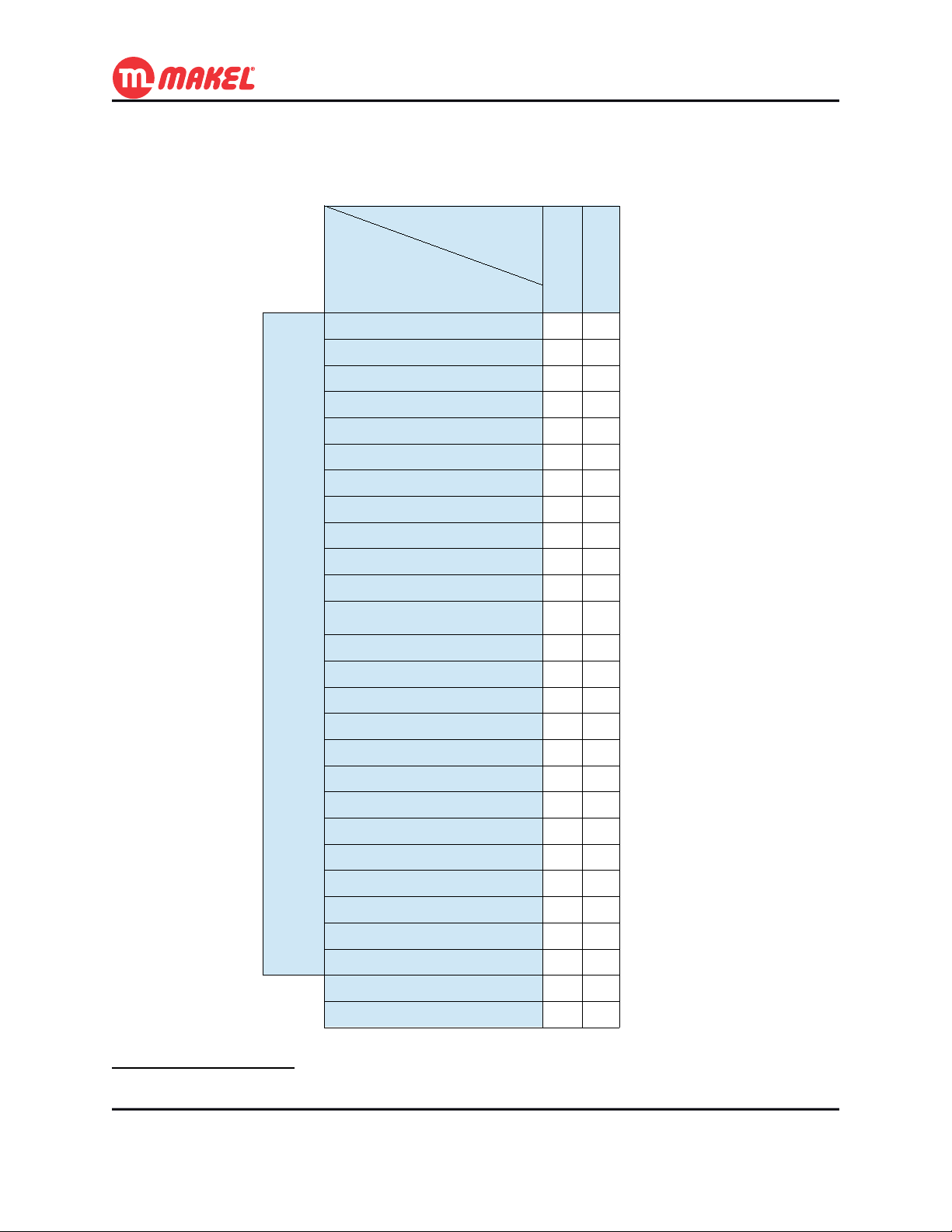
Table 2: Communication Objects existing in each Function
Function
Shutter andBlinds
Lighting
X
X
X
X
X
X
X
X
X
X
X
X
Per
Channel
Communication
Object Name
On / Off
Start / Stop Timer
Priority On / Off
Scene Control
Time Limited Toggle Switch
Reset Working Time counter
Timer delay (seconds)
Working t. limit reached Ind.
Working Timer counter Ind.
Pre-warning Indication
Status Indication
Logic – [[Inv.] Authorize / AND / OR / XOR /
NAND / NOR / XNOR]
Jamming
Move Up / Down
[Slat Angle | ]Stop Up / Down
Priority Move Up / Down
Scene Control
Shutter Position (%)
Blinds Angle (°)
Shutter Position Indication
Blinds Angle Indication
Up Status Indication
Down Status Indication
Rain Alarm
Wind Alarm
Restore Scenes
Maintenance Mode
X
X
X
X
X
X
X
X
X
X
X
X
X X
X X
X X
1
1 For further detailed information about the Communication Objects see Appendix C - Detailed description of
Communication objects.
User’s Manual Page 9

3 GETTING STARTED
User’s Manual Page 10

3 Getting Started
3 GETTING STARTED
3.1 Connecting for the first time
After connecting the MSAxxyy/CM device for the first time to the KNX/EIB bus, the user will see the
LEDs opening and closing preforming a circular sequence. This behavior means that the device hasn't
been loaded with a valid ETS™' application yet. The same behavior may be observed when an invalid
application is loaded into the device.
While signalising no application loaded, the device can be manually operated by pressing the Manual
Mode button and by pressing any of the channels' buttons. However, in this mode a couple of channels (1
and 2, 3 and 4, 5 and 6, ...) cannot not be both “On” at the same time. This is a characteristic of the
device for avoiding unintended short-circuit of shutters and blinds devices; if one of the relays from the
pair is closed and the other is asked to close, the device will first open the first and then proceed to close
the one that as been requested2.
3.2 Downloading application with ETS™
If it's the first time that the device will be programmed, you must define the Individual Address via
ETS™ interface. You must also press the programming button on the device for allowing ETS™ to
identify the target device. You will know that the device is in programming mode when the programming
LED turns on. During programming process the programming LED and the programming mode will
automatically turn off.
The Individual Address is normally written once, however if it's necessary to re-write the Individual
Address, the programming button must be pressed.
Once the device has its Individual Address, the device can be configured according to the project needs
using ETS™ application, selecting “Download Application”.
2 The minimum gap (both remain “Off” before turning “On” the requested channel) is of 40ms.
User’s Manual Page 11

4 DETAILED FUNCTIONS DESCRIPTION
User’s Manual Page 12
4 Detailed Functions Description
4 DETAILED FUNCTIONS DESCRIPTION
In this section all the functions will be introduced and explained in detail, as well as explained the ETS™
Product Database usage. This information should be enough for the installer to understand the device
operation in any of the functions and to configure it with the ETS™ database.
4.1 General Configuration
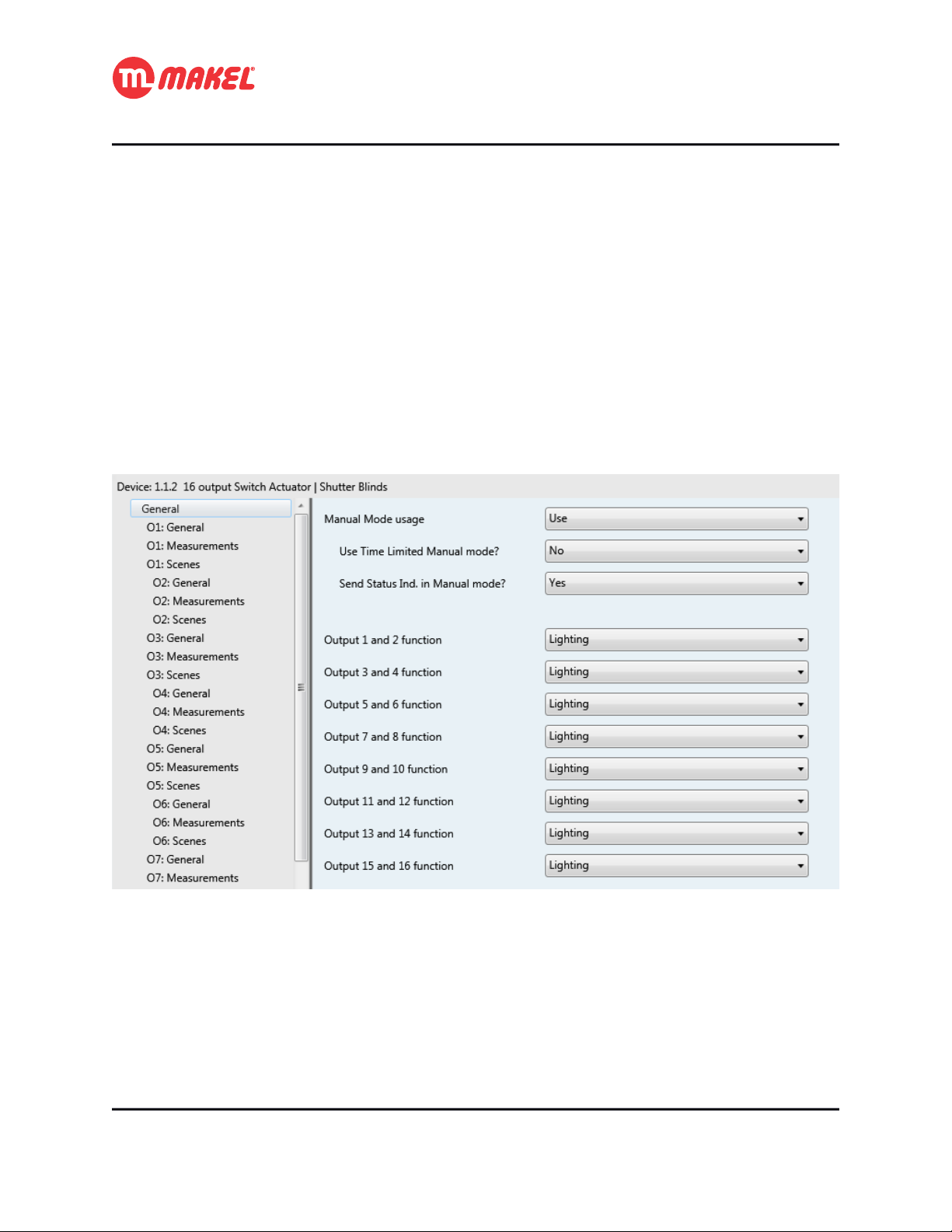
In ETS™, when the general page is selected an environment similar with the one in Figure 1 shall be
displayed. Here it's possible to configure some parameters that will affect all the system. All the
parameters are explained in the Table 3.
Figure 1: General Configurations page
User’s Manual Page 13
4 Detailed Functions Description
Table 3: General configurations' parameters description
Parameter Description Values
Manual Mode usage Selects if the device can be set to Manual
Mode operation via Manual Mode button and
via Maintenance Mode CO
3
Use Time Limited Manual mode? Should the Manual Mode operation terminate
automatically after a certain amount of time?
4
Duration Amount of time after which the Manual Mode
operation should be automatically terminated.
5
Send Status Ind. In Manual
mode?
Output [x] and [x+1] function Selects the function of a pair of channels. Possible values:
If this parameter is set to “Yes”, then, even in
Manual Mode the device will send the
channels' status to the bus.
Possible values:
*Use
Not used
Possible values:
*No
Yes
Possible values:
*5min
10min
…
1h15min
Possible values:
No
*Yes
*Lighting
Shutters and Blinds
It's convenient to explain in more detail some of the parameters present in the General configurations'
page. The “Use Time Limited Manual mode?” if set to “No”, once the device enters in Manual Mode
by pressing Manual Mode button or by sending message via “Maintenance Mode” CO it will leave
that mode just by pressing again the Manual Mode button or be sending message to the CO. However, if
the parameter is set to “Yes” the parameter “Duration” is shown; When the device is set to Manual Mode
via Manual Mode button or via CO it will leave this mode if the amount of time set in “Duration”
parameter expires or if Manual Mode button is again pressed or message is sent to the “Maintenance
Mode” CO.
The parameter “Send Status Ind. In Manual mode?” when set to “Yes” will allow the device to, when
in Manual Mode, send the channels status to the bus (all the incoming messages to device will still be
ignored). When set to “No” the device wont send the channels' status to the bus.
The “Manual Mode usage”, when configured to “Use” will make available one Communication Object:
[input] “General – Maintenance Mode”: Sending “True” sets the device to
maintenance mode.
3 Visible if “Manual Mode usage” is set to “Use”
4 Visible if “Use Time Limited Manual mode” is set to “Yes”
5 Visible if “Manual Mode usage” is set to “Use”
User’s Manual Page 14

4 Detailed Functions Description
With this communication object it's possible to set/unset the device to Manual Mode.
Depending on “Output [x] and [x+1] function” different configurations become available, depending on
if the pair of switches are configured to be 2 Lighting channels or 1 Shutter and Blinds channel.
4.2 Lighting Configurations
Here are explained the configurations for each channel in case it is chosen to Lighting function. All the
channels working as Lighting have similar configurations. Whenever from the General configurations'
page a pair of channels is set to “Lighting” function, in the tabs list (left side) three new tabs per channel
will expand:
• O[x]: General
• O[x]: Measurements
• O[x]: Scenes
4.2.1 O[x]: General
In this configuration page it's possible to make general configurations of the channel. The configuration
page is like the one presented in Figure 2. The respective detailed descriptions are presented in Table 4.
The Channel's general COs are:
[input] “On / Off”: Controls the output's status6;
[input] “Priority On / Off”: Makes higher priority control of the output's status;
[input] “Jamming”: Sending “True” makes the channel to enter in blocking mode;
[output] “Status Indication”: Informs the output's status.
6 Further explanations in 4.2.1b
User’s Manual Page 15
 Loading...