

Page 1

USER’S
MANUAL
KNX
Switch Actuator
MSAxxyy-CM
Shutter & Blinds Actuator
Device Manipulation & ETS™ Application Description
May, 2015
Page 2

Revision Sheet
Release No. Date Revision Description
Rev. 0 22/05/2015 User’s Manual Created
Rev. 1 02/06/2015 Added more detailed descriptions to the functionalities
User’s Manual Page 2
Page 3

USER'S MANUAL
TABLE OF CONTENTS
Page #
1 GENERAL INFORMATION................................................................................................................ 6
1.1 System Overview.............................................................................................................................6
1.2 Acronyms and Abbreviations..........................................................................................................6
2 SYSTEM SUMMARY........................................................................................................................... 8
2.1 Application Functions Overview.................................................................................................... 8
2.2 Application Communication Objects.............................................................................................9
3 GETTING STARTED.......................................................................................................................... 11
3.1 Connecting for the first time.........................................................................................................11
3.2 Downloading application with ETS™..........................................................................................11
4 DETAILED FUNCTIONS DESCRIPTION......................................................................................13
4.1 General Configuration..................................................................................................................13
4.2 Lighting Configurations................................................................................................................15
4.2.1 O[x]: General 15
4.2.2 O[x]: Measurements 25
4.2.3 O[x]: Scenes 26
4.3 Shutter and Blinds.........................................................................................................................28
4.3.1 O[x]-[x+1]: General 29
4.3.2 O[x]-[x+1]: Scenes 34
4.3.3 O[x]-[x+1]: Alarms configurations 36
Appendix A - Logic operations.................................................................................................................40
User’s Manual Page 3
Page 4

I - AND (Logical Conjunction)...........................................................................................................40
II - OR (Logical Disjunction).............................................................................................................. 41
III - XOR (Exclusive disjunction).......................................................................................................41
IV - NOT (Negation)............................................................................................................................42
Appendix B - KNX Data types..................................................................................................................43
Appendix C - Detailed description of Communication objects................................................................46
I - Lighting........................................................................................................................................... 47
II - Shutter and Blinds.........................................................................................................................48
User’s Manual Page 4
Page 5

1 GENERAL INFORMATION
User’s Manual Page 5
Page 6

1 General Information
1 GENERAL INFORMATION
1.1 System Overview
This manual refers to the following devices for KNX bus:
• MSAxxyy-CM: xx Channels, with yy amperes of maximum current rating per channel Switch
Actuator / Shutter & Blinds actuator.
All of the variants of MSAxxyy family includes:
• 1 programming touch button with 1 LED that shows whenever programming mode is active;
• 1 Manual Mode enable/disable touch button with 1 LED that shows whenever Manual Mode is
active or not;
• xx touch buttons that controls each of the xx channels (if Manual Mode active) with xx LEDs
that shows the contact position of each of the channels.
1.2 Acronyms and Abbreviations
CO Communication Object
EIB European Installation Bus (former name to KNX; no longer in use)
GA Group Address
LED Light Emitting Diode
User’s Manual Page 6
Page 7

2 SYSTEM SUMMARY
User’s Manual Page 7
Page 8

2 SYSTEM SUMMARY
Table 1: Applications specifications
Specs
Variant
MSA04yy-CMA 62 250 250
MSA08yy-CMA 122 250 250
MSA12yy-CMA 182 250 250
MSA16yy-CMA 242 250 250
Number of
Communication Objects
Maximum number of
Group Addresses
Maximum number of
Associations
2.1 Application Functions Overview
The MSAxxyy-CMA ETS™' application provides the interface to individually configure each of the pair
of channels on the products MSAxxyy-CM with one of the following functions:
• Lighting;
• Shutters and Blinds.
Depending on the function set to each channel, the respective possible configurations and possible
available Communication Objects (COs) vary.
When configured to Lighting each of the switches (relays) is one channel, what means that one switch
can preforme the “On” and “Off” operation over a light (or group of lights under the same control).
However, when configured to Shutter and Blinds, in order to control “Up” and “Down” movements it
takes two switches (relays), one the activates the “Up” movement and other that activates the “Down”
movement.
User’s Manual Page 8
Page 9
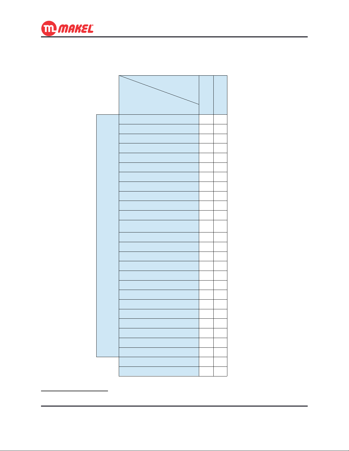
2.2 Application Communication Objects
Table 2: Communication Objects existing in each Function
Function
Shutter andBlinds
Lighting
X
X
X
X
X
X
X
X
X
X
X
X
Per
Channel
Communication
Object Name
On / Off
Start / Stop Timer
Priority On / Off
Scene Control
Time Limited Toggle Switch
Reset Working Time counter
Timer delay (seconds)
Working t. limit reached Ind.
Working Timer counter Ind.
Pre-warning Indication
Status Indication
Logic – [[Inv.] Authorize / AND / OR / XOR /
NAND / NOR / XNOR]
Jamming
Move Up / Down
[Slat Angle | ]Stop Up / Down
Priority Move Up / Down
Scene Control
Shutter Position (%)
Blinds Angle (°)
Shutter Position Indication
Blinds Angle Indication
Up Status Indication
Down Status Indication
Rain Alarm
Wind Alarm
Restore Scenes
Maintenance Mode
X
X
X
X
X
X
X
X
X
X
X
X
X X
X X
X X
1
1 For further detailed information about the Communication Objects see Appendix C - Detailed description of
Communication objects.
User’s Manual Page 9
Page 10

3 GETTING STARTED
User’s Manual Page 10
Page 11

3 Getting Started
3 GETTING STARTED
3.1 Connecting for the first time
After connecting the MSAxxyy/CM device for the first time to the KNX/EIB bus, the user will see the
LEDs opening and closing preforming a circular sequence. This behavior means that the device hasn't
been loaded with a valid ETS™' application yet. The same behavior may be observed when an invalid
application is loaded into the device.
While signalising no application loaded, the device can be manually operated by pressing the Manual
Mode button and by pressing any of the channels' buttons. However, in this mode a couple of channels (1
and 2, 3 and 4, 5 and 6, ...) cannot not be both “On” at the same time. This is a characteristic of the
device for avoiding unintended short-circuit of shutters and blinds devices; if one of the relays from the
pair is closed and the other is asked to close, the device will first open the first and then proceed to close
the one that as been requested2.
3.2 Downloading application with ETS™
If it's the first time that the device will be programmed, you must define the Individual Address via
ETS™ interface. You must also press the programming button on the device for allowing ETS™ to
identify the target device. You will know that the device is in programming mode when the programming
LED turns on. During programming process the programming LED and the programming mode will
automatically turn off.
The Individual Address is normally written once, however if it's necessary to re-write the Individual
Address, the programming button must be pressed.
Once the device has its Individual Address, the device can be configured according to the project needs
using ETS™ application, selecting “Download Application”.
2 The minimum gap (both remain “Off” before turning “On” the requested channel) is of 40ms.
User’s Manual Page 11
Page 12

4 DETAILED FUNCTIONS DESCRIPTION
User’s Manual Page 12
Page 13
4 Detailed Functions Description
4 DETAILED FUNCTIONS DESCRIPTION
In this section all the functions will be introduced and explained in detail, as well as explained the ETS™
Product Database usage. This information should be enough for the installer to understand the device
operation in any of the functions and to configure it with the ETS™ database.
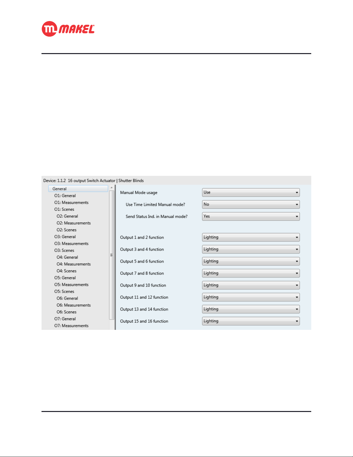
4.1 General Configuration
In ETS™, when the general page is selected an environment similar with the one in Figure 1 shall be
displayed. Here it's possible to configure some parameters that will affect all the system. All the
parameters are explained in the Table 3.
Figure 1: General Configurations page
User’s Manual Page 13
Page 14
4 Detailed Functions Description
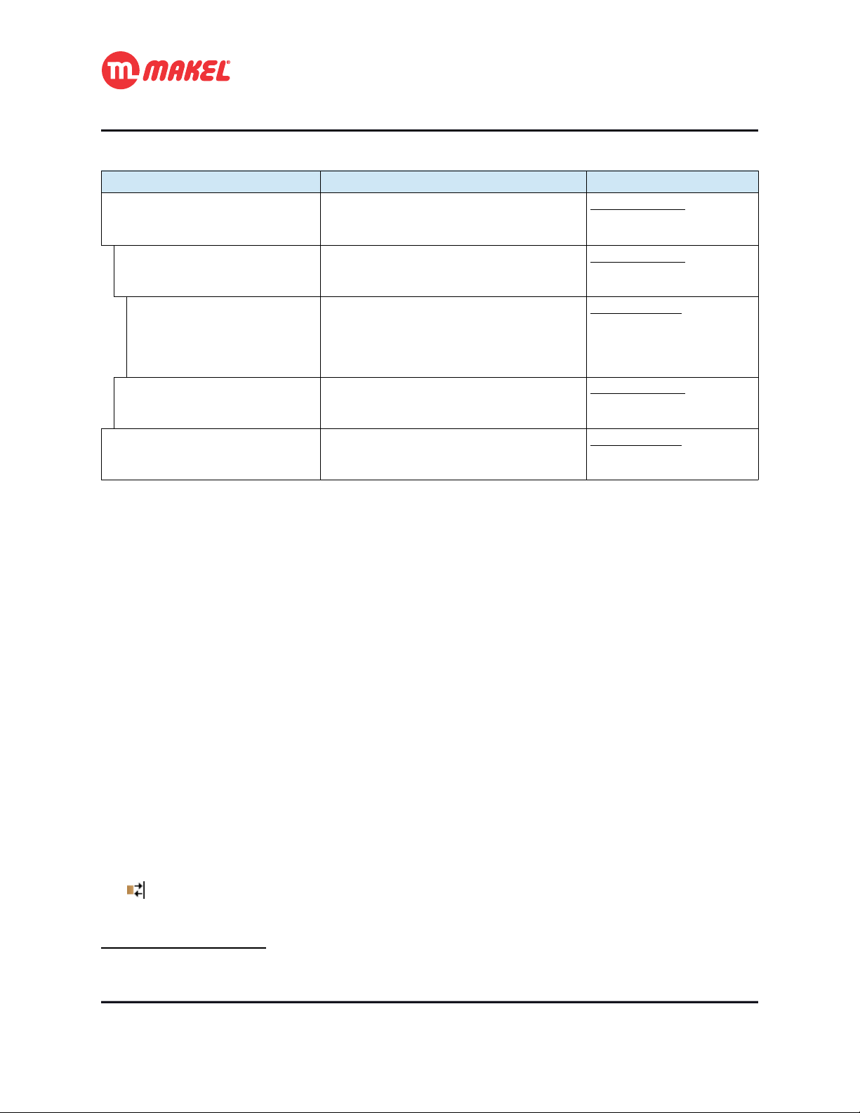
Table 3: General configurations' parameters description
Parameter Description Values
Manual Mode usage Selects if the device can be set to Manual
Mode operation via Manual Mode button and
via Maintenance Mode CO
3
Use Time Limited Manual mode? Should the Manual Mode operation terminate
automatically after a certain amount of time?
4
Duration Amount of time after which the Manual Mode
operation should be automatically terminated.
5
Send Status Ind. In Manual
mode?
Output [x] and [x+1] function Selects the function of a pair of channels. Possible values:
If this parameter is set to “Yes”, then, even in
Manual Mode the device will send the
channels' status to the bus.
Possible values:
*Use
Not used
Possible values:
*No
Yes
Possible values:
*5min
10min
…
1h15min
Possible values:
No
*Yes
*Lighting
Shutters and Blinds
It's convenient to explain in more detail some of the parameters present in the General configurations'
page. The “Use Time Limited Manual mode?” if set to “No”, once the device enters in Manual Mode
by pressing Manual Mode button or by sending message via “Maintenance Mode” CO it will leave
that mode just by pressing again the Manual Mode button or be sending message to the CO. However, if
the parameter is set to “Yes” the parameter “Duration” is shown; When the device is set to Manual Mode
via Manual Mode button or via CO it will leave this mode if the amount of time set in “Duration”
parameter expires or if Manual Mode button is again pressed or message is sent to the “Maintenance
Mode” CO.
The parameter “Send Status Ind. In Manual mode?” when set to “Yes” will allow the device to, when
in Manual Mode, send the channels status to the bus (all the incoming messages to device will still be
ignored). When set to “No” the device wont send the channels' status to the bus.
The “Manual Mode usage”, when configured to “Use” will make available one Communication Object:
[input] “General – Maintenance Mode”: Sending “True” sets the device to
maintenance mode.
3 Visible if “Manual Mode usage” is set to “Use”
4 Visible if “Use Time Limited Manual mode” is set to “Yes”
5 Visible if “Manual Mode usage” is set to “Use”
User’s Manual Page 14
Page 15

4 Detailed Functions Description
With this communication object it's possible to set/unset the device to Manual Mode.
Depending on “Output [x] and [x+1] function” different configurations become available, depending on
if the pair of switches are configured to be 2 Lighting channels or 1 Shutter and Blinds channel.
4.2 Lighting Configurations
Here are explained the configurations for each channel in case it is chosen to Lighting function. All the
channels working as Lighting have similar configurations. Whenever from the General configurations'
page a pair of channels is set to “Lighting” function, in the tabs list (left side) three new tabs per channel
will expand:
• O[x]: General
• O[x]: Measurements
• O[x]: Scenes
4.2.1 O[x]: General
In this configuration page it's possible to make general configurations of the channel. The configuration
page is like the one presented in Figure 2. The respective detailed descriptions are presented in Table 4.
The Channel's general COs are:
[input] “On / Off”: Controls the output's status6;
[input] “Priority On / Off”: Makes higher priority control of the output's status;
[input] “Jamming”: Sending “True” makes the channel to enter in blocking mode;
[output] “Status Indication”: Informs the output's status.
6 Further explanations in 4.2.1b
User’s Manual Page 15
Page 16

4 Detailed Functions Description
Figure 2: Channel's General configurations' page.
Table 4: Parameters in Channel's General configurations page.
Parameter Description Values
Use Timer? Selects if the timer functionalities are to
be activated and how.
7
Timer (default value) The length of the delay time. Possible values:
7
Timer operation mode Defines if the timer start triggers an On or
Off status.
7
Allow timer interruption with
Stop?
7
Consecutive presses multiply
time (within 10s)?
Defines if the timer can be stopped after
starting by sending Stop message.
Defines if the delay time can be
multiplied per n by send multiple Start
messages within 10 seconds.
Possible values:
*Not used
Use (normal Start=1; Stop=0)
Use (inverted Start=0; Stop=1)
1s, … *10s, ... 1min, 1min 15s, ….
2min, 3min, … 15min, 20min,
… 1h, 2h, … 1day
Possible values:
*On
Off
Possible values:
*No
Yes
Possible values:
*No
Yes
7 Visible if “Use Timer?” is set to value different than “Not used”.
User’s Manual Page 16
Page 17

7
Allow timer reset? Defines if the delay time is reset when a
Start message arrives.
7
Timer expiration Pre-Warning
usage
8
Timer expiration pre-warning The amount of time before timer
Defines how the timer expiration warning
shall be issued.
expiration that the warning must be
issued.
9
Pre-warning message type Defines the type of message to send via
“Pre-Warning” CO.
7
Timer Delay change via Com.
Obj.
Defines if the timer's delay time can be
changed via communication object, and
which is the Datapoint Type of the CO.
7
Time Limited Toggle Switch Defines the delay time for the switch-Off
10
when using the “Time Limited
Toggle Switch” CO.
“On/Off” Com.Obj. Function Defines the behaviour of the device upon
messages on the “On / Off” CO.
11
On Delay amount Defines the amount of delay to apply
between “On” message arrival and
switching the channel.
12
Off Delay amount Defines the amount of delay to apply
between “Off” message arrival and
switching the channel.
4 Detailed Functions Description
Possible values:
*No
Yes
Possible values:
Not used
Send Message via Pre-Warning CO
*Invert output (during 1s)
Send Message + Invert output
Possible values:
*15s, 30s, … 2min, 5min, 10min, …
20min
Possible values:
*On
Off
Possible values:
*Not used
DPT7.005 TimePeriodSec
(PDTUNSIGNED_INT)
DPT9.010 TimeValue
(PDT_KNX_FLOAT)
Possible values:
1s, 2s, [+1s]… *10s, ... 1min, 1min
15s, [+15s] …. 2min, 3min,
[+1min]… 15min, 20min,
[+15min]… 1h, 2h, [+1h]…
1day
Possible values:
*On / Off
Delayed On (immediate Off)
Delayed Off (immediate On)
Delayed On / Off
Timer On
Timer Off
Possible values:
1s, 2s, [+1s]… *10s, ... 1min, 1min
15s, [+15s] …. 2min, 3min,
[+1min]… 15min, 20min,
[+15min]… 1h, 2h, [+1h]…
1day
Possible values:
1s, 2s, [+1s]… *10s, ... 1min, 1min
15s, [+15s] …. 2min, 3min,
[+1min]… 15min, 20min,
[+15min]… 1h, 2h, [+1h]…
1day
8 Visible if “Timer Pre-Warning expiration usage” is set to value different than “Not used”.
9 Visible if “Timer Pre-Warning expiration usage” is set to “Send Message via Pre-Warning CO” or “Send
Message + Invert output”
10 The operation of Time Limited Toggle Switch is not affected by the previous parameters.
11 Visible if “''On/Off'' Com.Obj. Function” set to “Delayed On (immediate Off)” or “Delayed On/Off”.
12 Visible if “''On/Off'' Com.Obj. Function” set to “Delayed Off (immediate On)” or “Delayed On/Off”.
User’s Manual Page 17
Page 18

4 Detailed Functions Description
13
Delay The length of the delay time. Possible values:
1s, 2s, [+1s]… *10s, ... 1min, 1min
15s, [+15s] …. 2min, 3min,
[+1min]… 15min, 20min,
[+15min]… 1h, 2h, [+1h]…
1day
Logic input function Defines the function the channel's extra
input CO.
Status after system start Defines the behaviour of the device after
a power restore.
Output contact type Defines the relay position for the “On”
and “Off” states.
Jamming usage How should the jamming/blocking
functionalities of the channel affect the
channel.
14
Use Time Limited Jamming? Should the jamming operation terminate
automatically after a certain amount of
time?
15
Duration Amount of time after which the Manual
Mode operation should be automatically
terminated.
Status after Manual Mode
operation
Define the behaviour when the Manual
Mode operation is terminated.
Status after Priority operation Define the behaviour when the Priority
operation is terminated.
Status after jamming Define the behaviour when the jamming
is terminated.
Possible values:
*Not used
Authorize “On/Off” Com.Obj.
AND
OR
XOR
Inverted Authorize “On/Off”
Com.Obj.
NAND
NOR
XNOR
Possible values:
*Maintain
Off
On
Scene [1...32]
Possible values:
*Off = Relay Open; On = Relay
Closed
Off = Relay Closed; On = Relay
Open
Possible values:
*Not used
If '1'
If '0'
Possible values:
*No
Yes
Possible values:
*5min
10min
…
1h15min
Possible values:
*Maintain
Previous status
Invert
Theoretical status without
[manual/priority/jamming]
On
Off
13 Visible if “''On/Off'' Com.Obj. Function” set to “Timer On” or “Timer Off”.
14 Visible if “Jamming usage” set to “Yes”.
15 Visible if “Use Time Limited Jamming?” set to “Yes”.
User’s Manual Page 18
Page 19

4 Detailed Functions Description
Some of the parameters presented in Table 4 should get some more attention in order to fully understand
they functionalities and impacts on the system operation.
a) Timer
The related COs are:
[input] “Start / Stop Timer”: control of the timer;
[input] “Time Limited Toggle Switch”: control of the toggle switch timer;
[input] “Timer delay (seconds)”: for modifying the timer delay;
The “Use Timer?” parameter allows to activate the set of Timer and Time Limited Toggle Switch
functionalities.
The “Timer (default value)” parameter is where the delay time can be defined. This value can be
changed at run-time via CO if “Timer Delay change via Com. Obj.” is set to a value different than “Not
used”.
“Timer operation mode” if set to “On”, when a “Start” message is received the output switches On and
switches Off once delay time is elapsed (or timer is terminated); if set to “Off”, when a “Start” message is
received the output switches Off and switches On once the delay time is elapsed (or timer is terminated).
The parameter “Allow timer interruption with Stop?” if set to “No”, when timer is running it wont be
stopped if a “Stop” message is received.
By setting “Consecutive presses multiply time (within 10s)?” to “Yes”, sending repeatedly n “Start”
messages (within 10 seconds after the first “Start” message) will cause the delay time to be multiplied per
n.
When “Allow timer reset?” is set to “Yes” receiving a “Start” message when timer is already running
will make it to be reset.
The parameter “Consecutive presses multiply time (within 10s)?” if set to “Yes”, in the first
10 seconds “Start” messages will multiply the timer and not reset it, even if “Allow timer
reset?” is set to “Yes”.
The “Timer expiration Pre-Warning usage” parameter enables the possibility of being notified that the
timer will expire within a selectable amount of time (defined with “Timer expiration pre-warning”).
This notification can be done by toggling the output status during 1 seconds, or by sending a binary
User’s Manual Page 19
Page 20

4 Detailed Functions Description
(defined with “Pre-warning message type”) message via “Pre-Warning” CO or both. The Figure 3
suggests a possible time diagram for timer operation when “Timer (default value)” is set to T_d, “Timer
operation mode” is set to “On”, “Timer expiration Pre-Warning usage” is set to “Send message +
Invert output”, “Timer expiration pre-warning” is set to T_warn and “Pre-warning message type” is
“On”; here the timer is started due to a received “Start” message and runs until expiration.
Figure 3: Timer operation example when Pre-Warning uses output status inversion and message.
Setting “Timer Delay change via Com. Obj.” defined if the timer delay can be changed at run-time via
CO, and which is the DPT of the CO with the time delay. The operation has immediate effect, meaning
that if the timer is running and a new time delay, smaller than the already elapsed time, is sent via
“Timer delay (seconds)” CO it will cause the timer to terminate; if the a larger value is sent then
the timer will expire just when the new value is reached. Also to be considered that the pre-warning will
occur (if active) even in the case the new value is closer to expiration than the defined value for pre-
warning; in Figure 4 it's shown a possible scenario that tries to illustrate the previous situation (the device
would be making use of “Timer Delay change via Com. Obj.” and “Timer expiration Pre-Warning
usage” set to “Send Message via Pre-Warning CO”).
User’s Manual Page 20
Page 21

4 Detailed Functions Description
Figure 4: "Timer delay (seconds)" usage example - warning time impact.
No matter the selection of the timer related parameters, the operation of Time Limited Toggle Switch wont
be affected.
The parameter “Time Limited Toggle Switch” appears under the same group (“Use Timer?”), however it
implements a separated functionality, not affected by the previous parameters. This function allows to
turn On a channel for a certain amount of time, after which the channel will turn Off; sending Off
message immediately turns Off the channel.
If the Timer is running and Time Limited Toggle Switch is set “On” the Timer is immediately terminated; if
the Time Limited Toggle Switch is in process and Timer is started the Time Limited Toggle Switch is
terminated. Sending “Off” via “Time Limited Toggle Switch” CO while if it wasn't preceded
by an “On” message there will be no effect; the same applies to the Timer if a “Stop” message is sent to
“Start / Stop Timer” CO without a “Start” preceeding it.
User’s Manual Page 21
Page 22

4 Detailed Functions Description
b) “On/Off” Communication Object Functions
The COs that are related with this functionality are:
[input] “On / Off”: controls the output's status according to the selection in “''On/Off''
Com.Obj. Function”;
The function executed when a message arrives to the “On / Off” CO can be defined with the
parameter “''On/Off'' Com.Obj. Function”. When set to its default value “On/Off”, when an “On”
message is received the output switches to the On position; if an “Off” message is received the output
switches to its Off position. Three delayed modes are available: “Delayed On”, “Delayed Off” and
“Delayed On/Off”; and two timer modes: “Timer On” and “Timer Off”. If the parameter is set to
“Delayed On (immediate Off)” upon arrival of “On” message in the “On / Off” CO the output status
will switch to its On position just after the time defined in “On Delay amount”, however an “Off”
message will switch the output to its Off position immediately; for “Delayed Off (immediate On)” the
behavior is analogous; when the parameter is set to “Delayed On/Off” both On and Off output switch are
delayed. The delay is interrupted by the opposite message and restarted if the same message is sent (last
message overrides previous).
If the parameter is set to one of the “Timer” functionalities, its operation will be similar to the description
in 4.2.1a when the parameters “Allow timer interruption with Stop?” is set to “Yes”, “Consecutive
presses multiply time (within 10s)?” is set to “No”, “Allow timer reset?” set to “Yes” and without pre-
warning.
c) Logic functions
The COs related with logic functions are:
[input] “Logic - [FUNCTION]”: the input CO of the logic function;
It's possible to use one more input CO in combination with the “On / Off” CO to control the output
status. That is done by selecting the desired operation from the “Logic input function” parameter.
Chosing “Autorize ''On/Off'' Com.Obj.” will allow the operation of “On /Off” CO just if “Logic –
Authorize” CO is “True”, otherwise sending messages to “On /Off” CO has no effect; if the
parameter is set to “Inverted Autorize ''On/Off'' Com.Obj.” the operation of “On /Off” CO is enabled if
“Logic – Inv. Authorize” CO is “False”.
User’s Manual Page 22
Page 23

4 Detailed Functions Description
In case the parameter “Logic input function” is set to any other logic operation (AND, OR, XOR,
NAND, NOR, XNOR) to the “On / Off” CO is applied the selected logic operation with the logic
input CO and the “On / Off” function is processed according to the resulted value. In Figure 5 is presented
a possible scenario when “On / Off” uses “Delayed On” combined with logic input function AND.
Figure 5: "On / Off" configured to "Delayed On" and using logic "AND".
d) Channel status after system start / power recover
The behavior of each output of the device when it's started, for example after a power failure, can be
defined by setting the parameter “Status after system start” to the desired value. If the parameter is set
to “Maintain”, at power failure the device tries to save its current output status and restores it at power
restore; it can be defined the channel to turn “On” or “Off” or to set to a defined scene.
e) Channel output contact type
The definition of the “On” and “Off” position of the channel's switch is done in the parameter “Output
contact type”.
f) Jamming
The directly related COs are:
[input] “Jamming”: control of the jamming;
User’s Manual Page 23
Page 24

4 Detailed Functions Description
The channel may additionally be blocked via “Jamming” CO it “Jamming usage” is set to be used. It
can be blocked if “Jamming” CO receives “TRUE” (parameter set to “If '1'”) or blocked if
“Jamming” CO receives “FALSE” (parameter set to “If '0'”).
It's also possible to limit the time extension for which the channel remains blocked. This is is done the
setting “Use Time Limited Jamming?” to “Yes” and by selecting the duration in the parameter
“Duration”.
g) Channel status after overriding operations
Manual operation, priority and jamming are considered overriding operations since they impose a certain
output status. The status the output takes when any of those overriding operations is ended can be defined
in the parameters “Status after [Manual Mode operation/Priority operation/jamming]”. Setting this
parameter to “Maintain” causes the channel to keep that status that was imposed by the overriding
operation; if the parameter is set to “Previous status”, when the overriding operation terminates the
channel's output is set to its status just before the time the overriding operation starts; if parameter is set to
“Invert”, when the overriding operation ends the output status inverts the output imposed by the
overriding operation; setting the parameter to “On” causes the channel to go to “On” status when the
overriding operation terminates; setting the parameter to “Off” causes the channel to go to “Off” status
when the overriding operation terminates; by chosing “Theoretical status without
[manual/priority/jamming]” causes the channel's output to go to the status it would be in case the
overriding operation didn't occur.
In Figure 6 is shown the time diagram of a possible scenario in which the device is configured with
“Jamming usage” to “If '1'”, “Use Time Limited Jamming?” set to “Yes”, “Duration” set to
T_jamming; “''On/Off'' Com.Obj. Function” set to “Delayed On” with “On Delay amount” of T_d. In
this scenario, the “Jamming” CO takes a message that triggers the beginning of the channel's jamming
for a duration of T_jamming; meanwhile “On / Off” CO takes “On” message, once the jamming
period expired the “On” message is taken in consideration and the “On Delay” is initiated.
If one operation is already in course that operation will not be blocked, this means, for
instance, if a “Delayed On” operation is in course when a jamming/priority/Manual mode
message is received, that “Delayed On” operation will continue and the channel will switch.
User’s Manual Page 24
Page 25

4 Detailed Functions Description
Figure 6: Time Limited Jamming example with "Theoretical Status without jamming" and
"Delayed On" function.
4.2.2 O[x]: Measurements
The usage of this functionality makes available the following COs:
[input] “Reset Working Time counter”: Sending “True” resets the counter;
[output] “Working t. limit reached Ind.”: Sends “True” when the counter
reaches the defined limit;
[output] “Working Time counter Ind.”: Gives the counter every hour or by
reading (the counter is in seconds);
When the channel is set to “Lighting” function it is possible to measure the amount of working time of
each of the channels. Additionally it's possible to make the device issue a message whenever a certain
channel reaches a certain amount of working time. This can be useful, for example, for getting warning
that a lamp/group of lamps is reaching its end of life. The configuration page is like the one presented in
Figure 7. The respective detailed descriptions are presented in Table 5.
User’s Manual Page 25
Page 26

4 Detailed Functions Description
Figure 7: Channel's Measurements configuration page.
Table 5: Parameters in Channel's General configurations page.
Parameter Description Values
Use working duration counter? Selects if working time counter is to be
used for the channel.
16
Limit to send alert message
(hours)
16
Output status to measure Defines which is the channel status to be
16
Counter direction Defines if the counter must count from 0
The amount of time after which a
message must be sent via “Working
t. limit reached Ind.” CO.
measured.
to Limit or from Limit to 0.
Possible values:
*No
Yes
Min: 0h
Max: 500000h
Default: 1000h
Possible values:
*On
Off
Possible values:
*Increment
Decrement
The parameter “Limit to send alert message (hours)” defines the limit after which a message must be
issued informing that the limit has been reached. The parameter “Output status to measure” selects
which is the output status that must be measured as working.
4.2.3 O[x]: Scenes
The related COs are:
[input] “Scene Control”: sets a scene or requests learn;
All the Channels have available from “Scene 1” to “Scene 32” for configuration. Each of the scenes can
be configured to a specific action that may, or may not, depending on the installation settings, change at
run time. In case changes can be made after configuration with ETS, those changes are persistent, which
16 Visible if “Use working duration counter?” set to “Yes.”
User’s Manual Page 26
Page 27

4 Detailed Functions Description
means, even after a power dow followed by a power restore the changes will be kept. However, restoring
the scenes to the configuration time settings is possible via “Restore Scenes” CO; this process will
restore all the scenes form all the channels to its setting of ETS configurations deployment.
The configuration page for Scenes is as presented in Figure 8. The parameters are described in Table 6.
Figure 8: Channel's Scenes configuration page.
Table 6: Parameters in Button's configuration page for "Toggle Switch" function.
Parameter Description Values
Scene learn allowed? Defines if the device will recognise the scene
“learn” command and memorise its current
status to the respective scene.
Output status for scene [1...32] Defines the channel's behaviour for a certain
scene number.
The Communication Object “Restore Scenes” affects all the channels.
Possible values:
No
*Yes
Possible values:
*Not involved
On
Off
User’s Manual Page 27
Page 28

4 Detailed Functions Description
4.3 Shutter and Blinds
Here are explained the configurations for each channel in case it is chosen to Shutter and Blinds function.
All the channels working as Shutter and Blinds have similar configurations. Whenever from the General
configurations' page a pair of channels is set to “Shutter and Blinds” function, in the tabs list (left side)
three new tabs per pair of channel will expand:
• O[x]-[x+1]: General
• O[x]-[x+1]: Scenes
• O[x]-[x+1]: Alarms configurations
Figure 9: Shutter and Blinds control explanation.
In Figure 9 it's exposed the control of Shutter and Blinds. For initiating the down movement first the
blinds will go to 180°, just after that the down movement occurs; for the up movement first the blinds go
to 0°, just after the up movement is initiated. It's supposed the shutter and blinds actuator to be controlled
via two lines. All the position related measures are time based, which may not give good precision in
some cases, however most electric shutter and blinds don't provide means of feedback.
In next each of the configuration pages is going to be explained in more detail, as well some working
examples will be presented.
User’s Manual Page 28
Page 29

4.3.1 O[x]-[x+1]: General
The COs involved with general function of shutter and blinds control are:
[input] “Move Up / Down”: Controls the movement direction;
[input] “[Slat Angle |] Stop Up / Down”: [Steps the blinds in certain direction]
stops the movement;
[input] “Shutter Position (%)”: Sets the shutter to a specific position17;
[input] “Blinds [Position (%)/Angle (°)]”: Sets the blinds to a specific
[position/angle];
[input] “Jamming”: Blocks the channel's communication with remaining COs;
[output] “Shutter Position Indication”: Informs about the Shutter's current
position;
[output] “Blinds [Position/Angle] Indication”: Informs about the Blinds'
current [position/angle];
[output] “Up Status Indication”: Informs about the Up movement status (“True” if
moving up, “False” otherwise);
[output] “Down Status Indication”: Informs about the Down movement status
(“True” if moving down, “False” otherwise);
4 Detailed Functions Description
In Figure 10 it's shown the General configurations page's defaults for Shutter and Blinds pair of channels,
and further detailed description is given in the Table 7.
17 For this to work correctly the parameters “Time for complete [up/down] movement (s)” have to be correctly
set.
User’s Manual Page 29
Page 30

4 Detailed Functions Description
Figure 10: Channel's General configuration page (shutter and blinds).
Table 7: Parameters in General configuration page for Shutter and Blinds.
Parameter Description Values
Control also Blinds Defines if the system to be controlled
also includes blinds.
18
Blinds step time (x10ms) Defines the length of one blinds' step.
The value is multiplied per 10ms.
18
Number of blinds steps Defines the number of steps (with the
defined length) are needed for a full
movement of the blinds.
18
Blinds position control CO type Defines which datapoint type is to be
used for control the blinds position.
Time for complete up movement
(s)
Defines the amount of time it takes for
the shutter to go from totally closed to
totally opened.
Time for complete down
movement (s)
Defines the amount of time it takes for
the shutter to go from totally opened to
totally closed.
Possible values:
*No
Yes
Min: 5 (50 ms)
Max: 255 (2550 ms)
Default: 20 (200ms)
Min: 1
Max: 255
Default: 10
Possible values:
*Angle [DPT_ID Angle 5.003]
Percentage [DPT_ID Scaling 5.001]
Min: 1
Max: 65535
Default: 120
Min: 1
Max: 65535
Default: 120
18 Visible is “Control also Blinds?” set to “Yes”.
User’s Manual Page 30
Page 31

4 Detailed Functions Description
Delay for direction inversion (x100
ms)
Defines the time gap between
movements when the shutter is moving
one direction and is told to move the
opposite direction.
Min: 5 (500 ms)
Max: 255 (25500 ms)
Default: 10 (1000 ms)
a) Blinds Control
Blinds control is not enabled by default and can be enabled by setting to “Yes” the “Control also
Blinds”. Enabling blinds control requires to define three more parameters that basically define how the
blinds are controlled. The value of “Blinds step time (x10ms)” multiplied by “Number of blinds steps”
must correspond to the total time the blinds take to make a full movement (180° to 0°).
When configured to control also blinds, when “Up” message is sent to “Slat Angle | Stop Up /
Down” CO and no movement is occurring, the device will drive the Up switch for de time defined in
“Blinds step time (x10ms)”; analogous for “Down” message. If a movement is in progress the
movement is stoped, no matter if the received message is “Up” or “Down” (see Figure 11).
In Figure 12 it's presented a possible situation of shutter and blinds control. It must be assumed that
initially the shutters are totally opened (meaning 0%) and the blinds with and angle of 0°. When the down
movement is started the blinds will start towards 180° which takes T_b_180 (“Blinds step time (x10ms)”
multiplied by “Number of blinds steps”), after the device starts counting “Time for complete down
movement (s)”; once this value is reached the shutter is considered totally closed and the down
movement stops; since before the movement the blinds angle was of 0°, the MSAxxyy will restore that
position by driving the up direction from of 180° towards of 0°, which takes T_b_180; once this time is
elapsed the movement is stopped. In the occurrence of a message to the blinds angle, 120° as in the
example, the necessary time to rotate the blinds from 0° to 120° is calculated ( T_b_120) and the down
direction is driven for that amount of time
User’s Manual Page 31
Page 32

4 Detailed Functions Description
Figure 11: Usage of "Slat Angle | Stop Up / Down" CO.
User’s Manual Page 32
Page 33

4 Detailed Functions Description
Figure 12: Example of shutter and blinds operation.
b) Channel status after system start / power recover
The position of each channel when the system is (re)started, for example after a power failure, can be
defined by setting the parameter “Status after system start” to the desired value. If this parameter is set
to “Last stored position”, at power failure the device attempts to save the channel's current positions for
shutter and blinds and, in case of success, when power is restored the device will set the saved values; it's
possible to set the channel to close (shutter at 100% and blinds 18 0°) when the system (re)starts or to
User’s Manual Page 33
Page 34

4 Detailed Functions Description
open (shutter at 0% and blinds 0°) by setting the parameter to “Close” or “Open” respectively; if specific
positions for shutter and blinds are desired then the scenes must be used (see 4.3.2).
c) Jamming
The directly related COs are:
[input] “Jamming”: control of the jamming;
The channel may additionally be blocked via “Jamming” CO it “Jamming usage” is set to be used. It
can be blocked if “Jamming” CO receives “TRUE” (parameter set to “If '1'”) or blocked if
“Jamming” CO receives “FALSE” (parameter set to “If '0'”).
It's also possible to limit the time extension for which the channel remains blocked. This is is done the
setting “Use Time Limited Jamming?” to “Yes” and by selecting the duration in the parameter
“Duration”.
d) Channel status after overriding operations
Manual operation, priority and jamming are considered overriding operations since they impose a certain
output status. The status the output takes when any of those overriding operations is ended can be defined
in the parameters “Status after [Manual Mode operation/Priority operation/jamming]”. Setting this
parameter to “Maintain” causes the channel to keep that status that was imposed by the overriding
operation; if the parameter is set to “Previous status”, when the overriding operation terminates the
channel's will set the sutter (and blinds) to the status just before the time the overriding operation starts;
setting the parameter to “Close” causes the shutter (and blinds) to go to closed status (shutter 100% and
blinds 180°) when the overriding operation terminates; setting the parameter to “Open” causes the the
shutter (and blinds) to go to opened status (shutter 0% and blinds 0°) when the overriding operation
terminates; by chosing “Theoretical status without [manual/priority/jamming]” causes the channel's
output to go to the status it would be in case the overriding operation didn't occur.
4.3.2 O[x]-[x+1]: Scenes
The COs related with scenes functionality are:
[input] “Scene Control”: Controls the scenes;
Every Shutter and Blinds channel can have a specific position (for the shutters and for the blinds) for a
certain scene number. All the Channels have available from “Scene 1” to “Scene 32” for configuration.
User’s Manual Page 34
Page 35

4 Detailed Functions Description
Each of the scenes can be configured to a specific action that may, or may not, depending on the
installation settings, change at run time. In case changes can be made after configuration with ETS, those
changes are persistent, which means, even after a power dow followed by a power restore the changes
will be kept. However, restoring the scenes to the configuration time settings is possible via “Restore
Scenes” CO; this process will restore all the scenes form all the channels to its setting of ETS
configurations deployment.
Scenes configuration page in its defaults can be seen in Figure 13 and detailed information in Table 8.
Figure 13: Shutter and Blinds' Channel Scenes configuration page.
Table 8: Parameters for Shutter and Blinds' Channel Scenes configuration.
Parameter Description Values
Scene learn allowed? Defines if the device will recognise the
scene “learn” command and memorise
its current status to the respective
scene.
Output status for scene [1...32] Defines the channel's behaviour for a
certain scene number.
19
Shutter position Defines the shutter's position for the
corresponding scene.
20
Blinds position Defines the Blinds' position for the
corresponding scene.
19 Visible if “Output status for scene[1...32]” is “Position”.
20 Visible if “Output status for scene[1...32]” is “Position” and “O[x]-[x+1]: General” → “Control also
Blinds?” is “Yes”.
User’s Manual Page 35
Possible values:
No
*Yes
Possible values:
*Not involved
Close
Open
Position
Min: 0%
Max: 100%
Default: 0%
Min: 0°
Max: 180°
Default: 0°
Page 36

4 Detailed Functions Description
4.3.3 O[x]-[x+1]: Alarms configurations
The COs related with alarms functions are:
[input] “Rain Alarm”: receiving “True” makes device to set to rain alarm position;
[input] “Wind Alarm”: receiving “True” makes device to set to wind alarm position;
Every Shutter and Blinds' channel may have associated a specific position with each of the available
alarm inputs. The device can handle two alarms, by default the wind alarm and rain alarm. The
configuration page of the alarms when both are activated is presented in Figure 14 and further details are
given in Table 9.
Figure 14: Shutter and Blinds' Alarms configuration page (when alarms in usage)
User’s Manual Page 36
Page 37

4 Detailed Functions Description
Table 9: Shutter and Blinds' Alarms configurations page description.
Parameter Description Values
Use rain alarm? Defines if the rain alarm is to be used. Possible values:
*No
Yes
21
Position for rain alarm Defines the behavior of the device
when rain alarm is triggered.
21
Alarm active if Defines the polarity of the alarm signal
(active if '1' or active if '0').
21
Status after alarm Defines the behavior of the device in
pos-alarm.
Use wind alarm? Defines if the wind alarm is to be used. Possible values:
22
Position for rain alarm Defines the behavior of the device
when wind alarm is triggered.
22
Alarm active if Defines the polarity of the alarm signal
(active if '1' or active if '0').
22
Status after alarm Defines the behavior of the device in
pos-alarm.
Possible values:
*Maintain
Close
Open
Scene [1...32]
Possible values:
*On
Off
Possible values:
*Maintain
Previous status
Theoretical status without alarm
Close
Open
*No
Yes
Possible values:
*Maintain
Close
Open
Scene [1...32]
Possible values:
*On
Off
Possible values:
*Maintain
Previous status
Theoretical status without alarm
Close
Open
a) Positions at Alarm
The position the shutter and blinds should assume when a specific alarm occurs can be set in “Position
for [rain/wind] alarm”. It's possible to set it not to react when the alarm occurrence is givin by setting
the parameter to “Maintain”; set it to “closed” (shutter at 100% and blinds at 180°); set it to “opened”
(shutter at 0% and blinds at 0°); or to the position defined in a certain scene.
21 Visible if “Use rain alarm?” is “Yes”.
22 Visible if “Use wind alarm?” is “Yes”.
User’s Manual Page 37
Page 38

4 Detailed Functions Description
b) Positions after Alarm
The position the shutter and blinds assume when an alarm is terminated is also possible to determine by
setting the desired value in the parameter “Status after alarm”. The shutter and blinds will remain in
alarm position when the alarm is terminated if the parameter is set to “Maintain”; setting the parameter to
“Previous status” will set the shutter and blinds to the position it was just before the beginning of the
alarm; if the parameter is set to “Theoretical status without alarm”, once the alarm is terminated the
shutter and blinds will go to the position they would be in case the alarm hadn't occurred (the last request
related with shutter and blinds positioning is kept); it's possible to “close” (shutter 100% and blinds 180°)
after alarm or to “open” (shutter 0% and blinds 0°).
c) Alarm input mode
The alarm can be indicate active with '1' and inactive with '0' if the parameter “Alarm active if” is set to
“On”; alarm active with '0' and inactive with '1' if the parameter is set to “Off”.
User’s Manual Page 38
Page 39

Appendixes
APPENDIXES
User’s Manual
Page 40

Appendixes
A∧ B ⇔ B∧ A
A∧(B∧C )⇔( A∧B)∧C
A∧(B∨C )⇔( A∧B)∨(A∧C )
APPENDIX A - LOGIC OPERATIONS
Each of the Lighting Channels can have one logic input (see 4.2.1), that can be used to control the output
status of the channel. In here, useful theoretical information about the four logic operations will be
presented.
These functions belongs to the algebra's subarea Boolean algebra, in which the values of the variables are
the truth values TRUE and FALSE, that commonly are denoted by '1' and '0', respectively.
I - AND (Logical Conjunction)
This operator can be represented by the symbol “ ”. ∧ A n-place logical operator AND results TRUE if n of
its operands are TRUE, otherwise the value is FALSE.
Main properties:
• Commutativity:
• Associativity:
• Distributivity:
;
;
;
Table 10: Truth tables for Conjunction Operation
Input Output Output Input Output
A B A∧B A B C A∧B C∧ A B C D A∧B C D∧ ∧
0 0 0 0 0 0 0 0 0 0 0 0
0 1 0 0 0 1 0 0 0 0 1 0
1 0 0 0 1 0 0 0 0 1 0 0
1 1 1 0 1 1 0 0 0 1 1 0
1 0 0 0 0 1 0 0 0
1 0 1 0 0 1 0 1 0
1 1 0 0 0 1 1 0 0
1 1 1 1 0 1 1 1 0
1 0 0 0 0
1 0 0 1 0
1 0 1 0 0
1 0 1 1 0
1 1 0 0 0
1 1 0 1 0
1 1 1 0 0
1 1 1 1 1
User’s Manual Page 40
Page 41

Appendixes
A∨ B⇔ B∨ A
A∨(B∨C )⇔(A∨ B)∨C
A∨(B∧C )⇔(A∨ B)∧( A∨C )
A⊕ B⇔ B⊕ A
A⊕(B⊕C )⇔(A⊕B)⊕C
II - OR (Logical Disjunction)
This operator can be represented by the symbol “ ”. A ∨ n-place logical operator AND results TRUE if at
least 1 of n operands is TRUE, if n operands are FALSE, then the result is FALSE.
Main properties:
• Commutativity:
• Associativity:
• Distributivity:
;
;
;
Table 11: Truth tables for Disjunction Operation
Input Output Output Input Output
A B A∨B A B C A∨B C∨ A B C D A∨B C D∨ ∨
0 0 0 0 0 0 0 0 0 0 0 0
0 1 1 0 0 1 1 0 0 0 1 1
1 0 1 0 1 0 1 0 0 1 0 1
1 1 1 0 1 1 1 0 0 1 1 1
1 0 0 1 0 1 0 0 1
1 0 1 1 0 1 0 1 1
1 1 0 1 0 1 1 0 1
1 1 1 1 0 1 1 1 1
1 0 0 0 1
1 0 0 1 1
1 0 1 0 1
1 0 1 1 1
1 1 0 0 1
1 1 0 1 1
1 1 1 0 1
1 1 1 1 1
III - XOR (Exclusive disjunction)
This operator can be represented by the symbol “⊕”. A n-place logical operator XOR results TRUE if one
odd number of operands is TRUE, otherwise the result is FALSE.
Main properties:
• Commutativity:
• Associativity:
User’s Manual Page 41
;
;
Page 42

Table 12: Truth tables for Exclusive Disjunction Operation
¬¬A⇔ A
¬¬¬A⇔ ¬A
¬(A∨B )⇔(¬A∧¬ B)
¬(A∧B )⇔(¬A∨¬ B)
Input Output Output Input Output
A B A⊕B A B C A⊕B C⊕ A B C D A⊕B C D⊕ ⊕
0 0 0 0 0 0 0 0 0 0 0 0
0 1 1 0 0 1 1 0 0 0 1 1
1 0 1 0 1 0 1 0 0 1 0 1
1 1 0 0 1 1 0 0 0 1 1 0
1 0 0 1 0 1 0 0 1
1 0 1 0 0 1 0 1 0
1 1 0 0 0 1 1 0 0
1 1 1 1 0 1 1 1 1
1 0 0 0 1
1 0 0 1 0
1 0 1 0 0
1 0 1 1 1
1 1 0 0 0
1 1 0 1 1
1 1 1 0 1
1 1 1 1 0
Appendixes
IV - NOT (Negation)
This operator can be represented by the symbol “¬”. Negation is unary (single-argument) logical operator.
Negation function takes Falsity to Truth and vice versa.
Main properties:
• Double negation:
• Distributivity (Morgan's law):
Table 13: Truth table for NOT Operation
and
A ¬A
0 1
1 0
;
and
;
User’s Manual Page 42
Page 43

APPENDIX B - KNX DATA TYPES
Table 14: Some of the KNX Data Points Types
DPT_ID DPT_Name Size (bits)
1.001 DPT_Switch 1
1.002 DPT_Bool 1
1.003 DPT_Enable 1
1.004 DPT_Ramp 1
1.005 DPT_Alarm 1
1.006 DPT_BinaryValue 1
1.007 DPT_Step 1
1.008 DPT_UpDown 1
1.009 DPT_OpenClose 1
1.010 DPT_Start 1
1.011 DPT_State 1
1.012 DPT_Invert 1
1.013 DPT_DimSendStyle 1
1.014 DPT_InputSource 1
1.015 DPT_Reset 1
1.016 DPT_Ack 1
1.017 DPT_Trigger 1
1.018 DPT_Occupancy 1
1.019 DPT_Window_Door 1
1.021 DPT_LogicalFunction 1
1.022 DPT_Scene_AB 1
1.023 DPT_ShutterBlinds_Mode 1
1.100 DPT_eat/Cool 1
2.001 DPT_Switch_Control 2
2.002 DPT_Bool_Control 2
2.003 DPT_Enable_Control 2
2.004 DPT_Ramp_Control 2
2.005 DPT_Alarm_Control 2
2.006 DPT_BinaryValue_Control 2
2.007 DPT_Step_Control 2
2.008 DPT_Direction1_Control 2
2.009 DPT_Direction2_Control 2
2.010 DPT_Start_Control 2
2.011 DPT_State_Control 2
2.012 DPT_Invert_Control 2
3.007 DPT_Control_Dimming 4
Appendixes
User’s Manual Page 43
Page 44

Appendixes
3.008 DPT_Control_Blinds 4
4.001 DPT_Char_ASCII 8
4.002 DPT_Char_8859_1 8
5.001 DPT_Scaling 8
5.003 DPT_Angle 8
5.004 DPT_Percent_U8 8
5.005 DPT_DecimalFactor 8
5.010 DPT_Value_1_Ucount 8
6.001 DPT_Percent_V8 8
6.010 DPT_Value_1_Count 8
6.020 DPT_Status_Mode3 8
7.001 DPT_Value_2_Ucount 16
7.002 DPT_TimePeriodMsec 16
7.003 DPT_TimePeriod10MSec 16
7.004 DPT_TimePeriod100MSec 16
7.005 DPT_TimePeriodSec 16
7.006 DPT_TimePeriodMin 16
7.007 DPT_TimePeriodrs 16
7.010 DPT_PropDataType 16
7.011 DPT_Length_mm 16
7.012 DPT_UElCurrentmA 16
7.013 DPT_Brightness 16
8.001 DPT_Value_2_Count 16
8.002 DPT_DeltaTimeMsec 16
8.003 DPT_DeltaTime10MSec 16
8.004 DPT_DeltaTime100MSec 16
8.005 DPT_DeltaTimeSec 16
8.006 DPT_DeltaTimeMin 16
8.007 DPT_DeltaTimers 16
8.010 DPT_Percent_V16 16
8.011 DPT_Rotation_Angle 16
9.001 DPT_Value_Temp 16
9.002 DPT_Value_Tempd 16
9.003 DPT_Value_Tempa 16
9.004 DPT_Value_Lux 16
9.005 DPT_Value_Wsp 16
9.006 DPT_Value_Pres 16
9.007 DPT_Value_umidity 16
9.008 DPT_Value_AirQuality 16
9.010 DPT_Value_Time1 16
9.011 DPT_Value_Time2 16
User’s Manual Page 44
Page 45

9.020 DPT_Value_Volt 16
9.021 DPT_Value_Curr 16
9.022 DPT_PowerDensity 16
9.023 DPT_KelvinPerPercent 16
9.024 DPT_Power 16
9.025 DPT_Value_Volume_Flow 16
... ... ...
Appendixes
User’s Manual Page 45
Page 46

Appendixes
APPENDIX C - DETAILED DESCRIPTION OF COMMUNICATION
OBJECTS
Depending on the device, the number of COs differs, and so it does some of their numbers. However, the
numbers, from device to device change according to an offset (Δ):
• MSA04yy-CM: Δ = 60
• MSA08yy-CM: Δ = 120
• MSA12yy-CM: Δ = 180
• MSA16yy-CM: Δ = 240
Table 15: General COs specification
Function #GO23 GO Name IN/OUT DPT
Restore Scenes Δ Restore Scenes IN 1.001
Maintenance
Δ+1
Maintenance Mode IN 1.001
23 First CO is the number 0, according to ETS™.
User’s Manual Page 46
Page 47

Appendixes
I - Lighting
Since all the channels are identical, also their COs have identical characteristics, differing only in their
number. The GO number increment per channel is ∂ = 15.
Table 16: Lighting Channel x's specific COs' description (x=1...n, where n is the number of
channels available)
Function #GO GO Name IN/OUT DPT
ON / OFF 0+x*∂ On / Off IN 1.001
Start / Stop Timer 1+x*∂ Start / Stop Timer IN 1.010
Priority On / Off 2+x*∂ Priority On / Off IN 1.001
Scene Control 3+x*∂ Scene Control IN 18.001
Time Limited Toggle Switch 4+x*∂ Time Limited Toggle Switch IN 1.001
Authorize 5+x*∂ Logic - Authorize IN 1.002
AND 5+x*∂ Logic - AND IN 1.002
OR 5+x*∂ Logic - OR IN 1.002
Logic
Jamming 7+x*∂ Jamming IN 1.002
Reset Working Time Counter 8+x*∂ Reset Working Time Counter IN 1.002
Timer delay (seconds)
Working Time Limit Reached indication 11+x*∂ Working t. limit reached Ind. OUT 1.002
Working Time Counter indication 12+x*∂ Working Time counter Ind. OUT 13.100
Timer expiration pre-warning 13+x*∂ Pre-warning Indication OUT 1.002
Output Status Indication 14+x*∂ Status Indication OUT 1.001
XOR 5+x*∂ Logic - XOR IN 1.002
Inverted Authorize 5+x*∂ Logic - Inv. Authorize IN 1.002
NAND 5+x*∂ Logic - NAND IN 1.002
NOR 5+x*∂ Logic - NOR IN 1.002
XNOR 5+x*∂ Logic - XNOR IN 1.002
9+x*∂ Timer delay (seconds) IN 7.005
9+x*∂ Timer delay (seconds) IN 9.010
User’s Manual Page 47
Page 48

Appendixes
II - Shutter and Blinds
Since all the channels are identical, also their COs have identical characteristics, differing only in their
number. The GO number increment is θ = 30.
Table 17: Shutter and Blinds Channel [x]-[x+1]'s specific COs' description (x=1...n-1, where n
is the number of channels available)
Function #GO GO Name IN/OUT DPT
Up / Down Control 0+x*θ Move Up / Down IN 1.008
Wind Alarm 1+x*θ Wind Alarm IN 1.002
Scene Control 3+x*θ Scene Control IN 18.001
Slat angle Up/Down and Stop Up/Down 4+x*θ Slat Angle | Stop Up / Down IN 1.008
Shutter Position 5+x*θ Shutter Position (%) IN 5.001
Blinds Position
Jamming 7+x*θ Jamming IN 1.002
Rain Alarm 8+x*θ Rain Alarm IN 1.002
Shutter Position Indication 10+x*θ Shutter Position Indication OUT 5.001
Blinds Position Indication
Up Movement Status Indication 14+x*θ Up Status Indication OUT 1.001
Down Movement Status Indication 29+x*θ Down Status Indication OUT 1.001
6+x*θ Blinds Angle (°) IN 5.003
6+x*θ Blinds Position (%) IN 5.001
11+x*θ Blinds Angle Indication OUT 5.003
11+x*θ Blinds Position Indication OUT 5.001
User’s Manual Page 48
 Loading...