

Make Audio Monitor, Annex Bookshelf, Annex Bookshelf / Monitor Assembly Instructions Manual
Page 1
Premium Audiophile
Basic Speaker Kit
Assembly Instructions
Model: Annex Bookshelf / Monitor
Make Audio Annex Basic Kit Assembly Instructions Revision 1.0 pg. 1
Page 2
Congratulations! Thank you for purchasing our professionally engineered speaker kit designed
for maximum acoustic performance and accuracy. All the assemblies of this kit have passed our
quality control program to ensure your Make Audio speaker kit build will be successful!
All parts required to assemble this kit are included. The only tool you require for assembly is a
Philips screwdriver.
IMPORTANT: Excessive paint buildup /thickness can prevent installation of the transducers into
the precision CNC machined front baffle. We suggested limiting the paint in the transducer
mortises (recesses or areas machined to clear the flange of the transducer) to one thin coat.
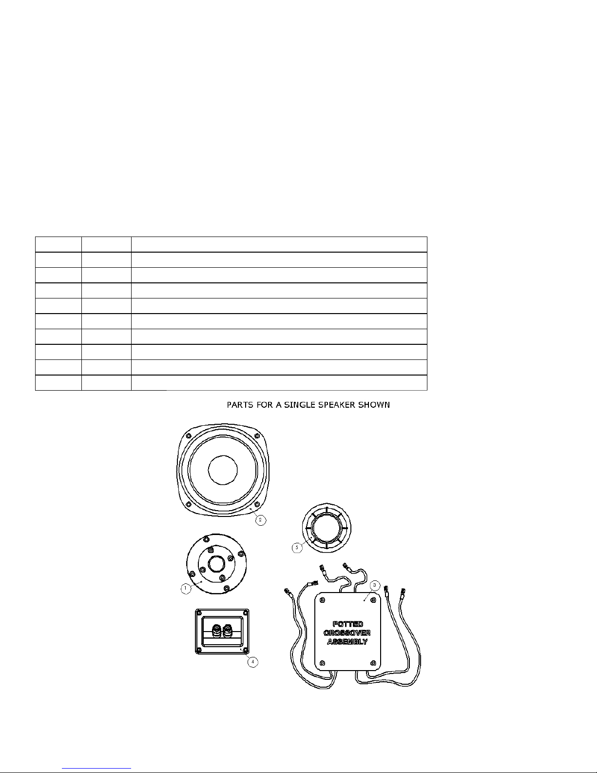
Section 1: Identify all parts in the package.
Bill of Materials
Quantity Item # Description
2 1 tweeter
2 2 woofer
2 3 crossover assembly
2 4 terminal cup
2 5 port, ABS, press fit, 2"ID x 5"
1 6 suggested cabinet drawings
1 assembly instructions (this document)
Make Audio Annex Basic Kit Assembly Instructions Revision 1.0 pg. 2
Page 3
Section 2: Speaker Sound Customization
Treble Level
Description
Low (
-
1dB
)
- Listening at high sound
pressure levels typically over 80dBA at the
- Reflective listening room; no carpets, drapes, bookshelves etc.
- Prefer less treble
Neutral ( 0dB )
- Reference level used for voicing in a calibrated average listening
- Listening at an average sound pressure level of 77
-
83 dBA
- Best balance for a wide range of music and recording qualities
High (+1dB )
- Usually listening at low sound pressure level below 77 dBA
- Listening room
acoustically treated with absorbers
- Listening to music genres that you prefer to be extra highly detailed
2.1 Treble Level
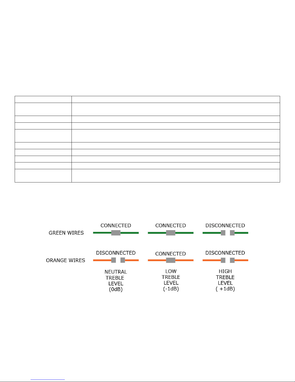
You have the option of selecting your preferred treble level before installing the crossover. Three
treble levels are available. The crossover is shipped with the treble set to the Neutral level (0dB
). By connecting/disconnecting the green and orange wire terminals highlighted below, the
treble level can be adjusted to low ( -1dB ) or high (+1dB ). The level changes are subtle but
audible.
Below is a table to help you choose the correct level.
listening position
Default
room with carpet, some drapes, furniture, etc.
and transparent
Make Audio Annex Basic Kit Assembly Instructions Revision 1.0 pg. 3
Page 4
2.2 Bass Level and Extension
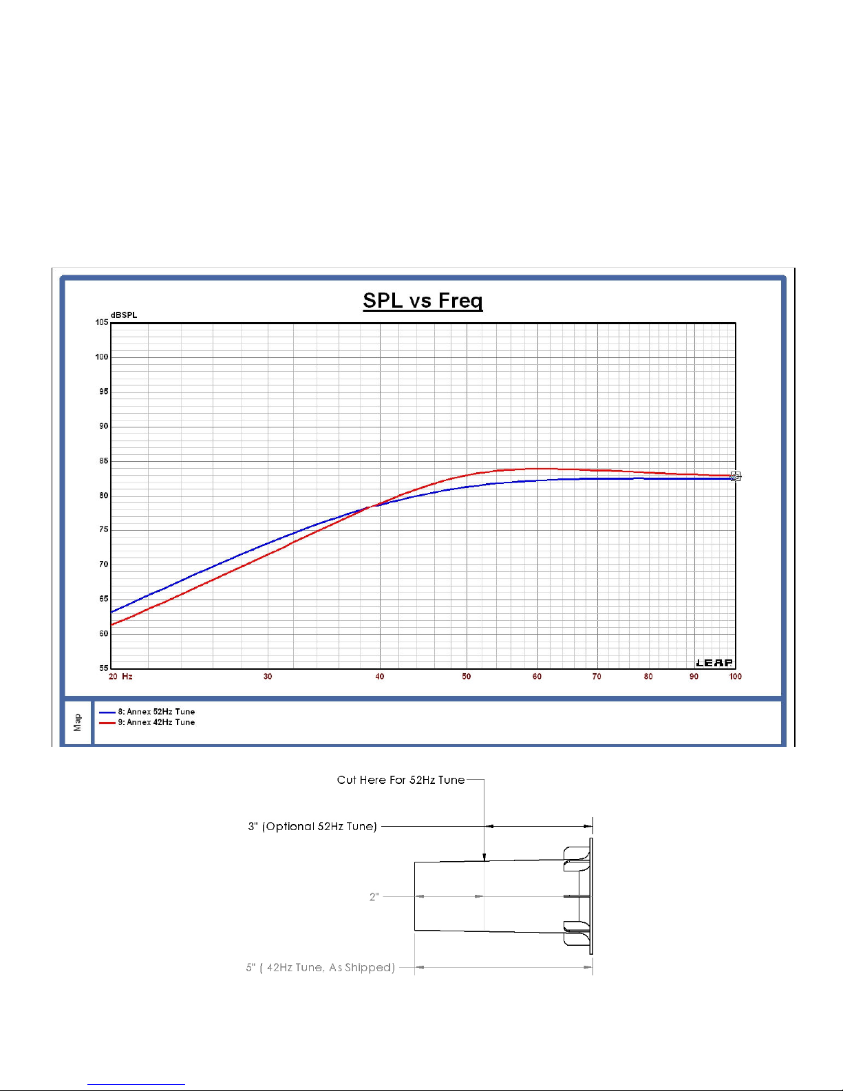
The Annex speaker bass reflex system is tuned to 42Hz using the port as shipped. This tune will
result in the best compromise between a neutral (flat) bass frequency response and optimal
transient response. If you prefer a slightly bass heavy frequency response, cutting 2” from the
smaller straight end of the port will increase the tuning to 52Hz and provide a couple DB of
additional bass output capability above this frequency however the transient response will be
slightly degraded and the lower cutoff frequency will increase. The bass effect is shown in the
graph below. The cut port can be glued back together with cynoacrylate (Crazy Glue) or joined
with duct tape.
Make Audio Annex Basic Kit Assembly Instructions Revision 1.0 pg. 4
Page 5
Section 3. Speaker Assembly
3.1 Crossover Installation
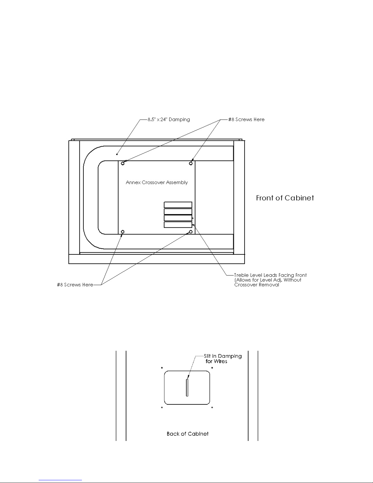
Position the crossover in the bottom of the upright cabinet and hand fit four #8 x ¾” screws
through the corners holes in the crossover and into the four holes in the bottom of the cabinet.
Once all four screws are aligned with the holes in the bottom panel, thread and tighten the
screws with a short Philips screw driver.
Only use the supplied screws and do not over-tighten them.
3.2 Damping Installation & Wiring
Position the 8.5” x 24” in the lower part of the cabinet in a u-shape as shown above. Glue is not
required to hold the damping in place. Using shape scissors, cut a 1” long slit in the damping
aligned with the rectangular opening in the back of the cabinet as shown below.
Make Audio Annex Basic Kit Assembly Instructions Revision 1.0 pg. 5
Page 6
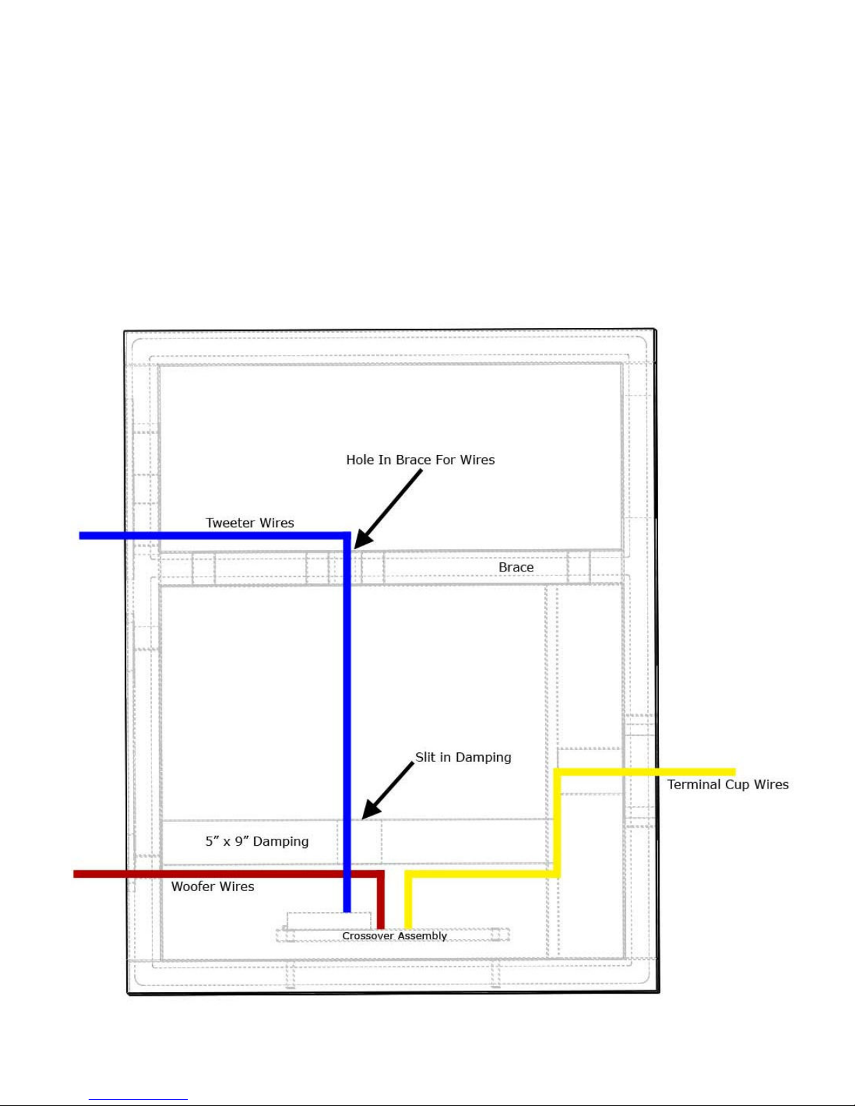
Thread the yellow+black crossover wires through the slit in the damping. Position the ends of
the red+black crossover wires at the bottom of woofer hole in the front baffle.
Cut a 1” long slit in the center of the 5” x 9” piece of damping. Tear off a ¾” x ¾” square of
damping from the corner. While threading the blue+black crossover wires through the slit,
position the 5” x 9” piece of damping on top of the crossover. Continue threading the blue+black
wires through the hole in the brace and stuff the hole with the ¾” x ¾” square of damping. Pull
the wires through the tweeter opening in the front baffle.
The wires will prevent the damping from directly on top of the crossover and a gap between
them is normal.
Make Audio Annex Basic Kit Assembly Instructions Revision 1.0 pg. 6
Page 7
3.3 Terminal Cup Installation
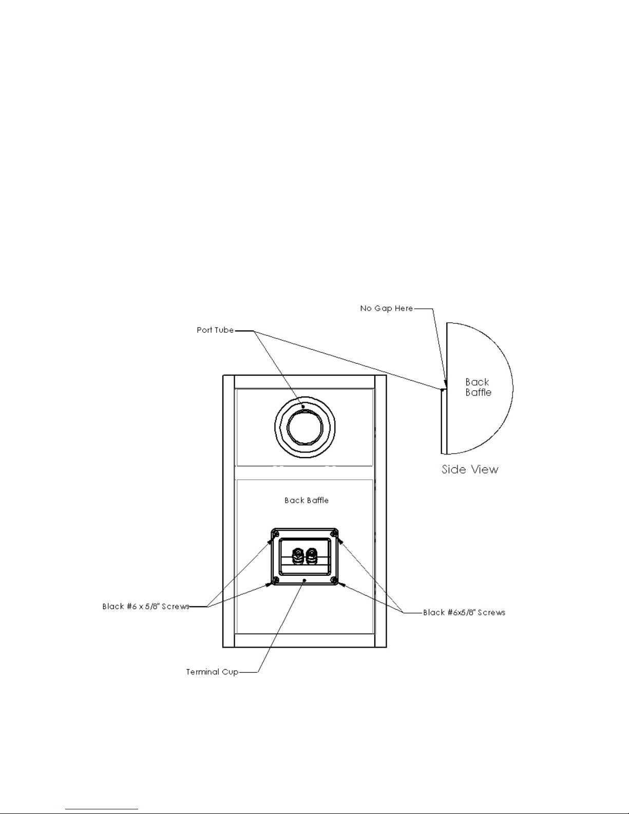
With the speaker cabinet lying front face down, push the female terminals of the yellow+black
wires on to the terminal cup male terminals with the black wire connecting to the black binding
post and the yellow wire connecting to the red binding post.
Push the terminal cup into the rectangular opening on the back baffle and secure it with four
black #6 x 5/8” screws. Do not over-tighten the screws.
3.4 Port Tube Installation
Press fit the port tube into the round opening on the back baffle. Use only the back of your hand
to apply pressure. Ensure the port is fully pushed down on the back baffle surface such that
there is no gap between the port tube flange and the baffle surface as highlighted below.
Make Audio Annex Basic Kit Assembly Instructions Revision 1.0 pg. 7
Page 8

3.5 Transducer Installation
With the speaker cabinet lying back face down, push the female terminals on the blue+black
wires on to the tweeter make terminals. To prevent excessive bending, support the back side of
the male terminal when pushing on the wire terminals.
Repeat with the red+black wires and the woofer.
Secure the transducers to the cabinet with the black #6 x 5/8” screws. Do not over-tighten the
screws. If using a cordless, ensure the torque setting is low and the transducer is protected from
a slipping bit with cardboard or your hand.
3.6 (Optional) Rubber Bumper Installation
Remove the rubber bumpers from their backing and push them on to each corner of the bottom
panel. The bumpers can also be installed on your speaker stands.
Congratulations! You have completed assembly of the Annex Bookshelf / Monitor Speaker.
If you have questions about this document or the assembly of your speaker, please contact us at
Make Audio Annex Basic Kit Assembly Instructions Revision 1.0 pg. 8
 Loading...