

Page 1
MT760
Page 2

Safety
International Safety Symbols
T
his sy
mbol, adjacent to another sy
mbol or terminal, indicates the user must refer to
the manual for further information.
T
his symbol, adjacent to a terminal, indicat es that, under normal use, hazardous
voltages may be present
D
ouble insulation
SAFETY NOTES
• Do not exceed the maximum allow
able input range of any
function
•
D
o
not apply
v
o
ltage to meter w
hen resistance function is selected.
• Set the function switch OFF when the meter is not in use.
WARNI
NGS
•
Set function sw
itch to the appropr
iate position before measuring.
• When measuring volts do not switch to current/resistance modes.
•
When changing ranges using the s elector sw
itch always disconnect the test leads from the
circuit under test.
• Do not exceed the maximum rated input limits.
CAUTIONS
Improper use of this meter can cause damage, sh ock, injury or death. Read and understand
this user manual before operating the meter.
Always remove the test leads before replacing the battery.
Inspect the condition of the test leads and the
meter itself for any
damage before operating the
meter. R
epair or replace any
damage before use.
Use great care w
hen making measurements if
the voltages are greater than 25VAC rms or
35VDC. These voltages are considered a shock hazard.
Remove the battery if the meter is to be stored for long peri ods.
Always discharge capacitors and remove power from the device under test before performing
Diode, R
esistance or Continuity
tests.
•
Voltage checks on electrical outlets can be diffi
cult and misleading because of
the uncertainty
of connection to the recessed electrical contac ts. Other means should be used to ensure that
the terminals are not "live".
• If the equipment is used in a manner not specified by the manufacturer, the protection
prov
ided by the equipment may be impaired.
Input Limits
Function
M
aximum Input
A AC, VDC
200A (PEAK 282.8A)
V DC, V AC
600V D
C/AC
Resistance, Continuity Test
600V D
C/AC
Meter Description
1. C
urrent clamp & Non-contact AC
voltage detector probe tip
2. Flashlight
3.
Non-contact AC vo
ltage(NCV) indicator light
4.
Flashlight on/off button
5.
R
o
tary
Function sw
ith
6. Cl
amp
trigger
7. LCD
display
8.
Select Peek hold, MAX/MI
N Hold
, DCA Zero,DC/ACV function button
Peak Hold function (only AC
A range)
DCA Zero (onl
y DCA rang
e)
MAX/MI
N Hold function (Use to
DCA,DCV,ACV, Resista
nce range
)
DC/ACV (s
elec
t DC Vor ACV )
9.
Data Hold & Backlight button
10.COM input jack
11.
V
jack
12.
Battery Cov
er
1 2
Page 3
I
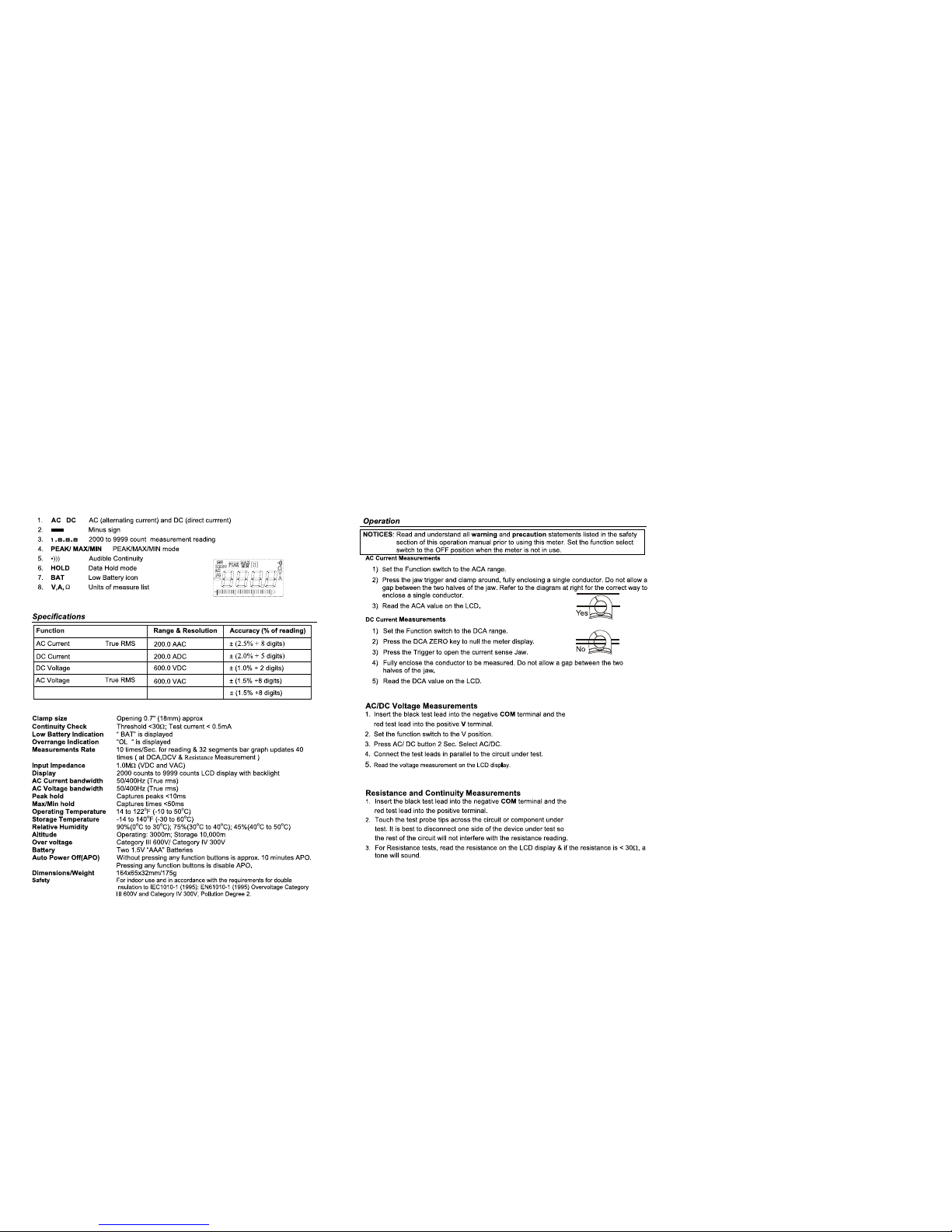
Resistance
9
99.
9
Ω
(50/60 Hz)
(50/60 Hz)
Page 4

Non-C
ontact A
C Voltage Measurements
1.Touch the probe tip to the hot conductor or inse rt into the hot side of the electrical outlet.
2.
If AC
voltage is present, the detector light will illuminate.
NOTE: The conductors in electrical cord sets are o ften tw
isted. For best results, rub the
probe tip along a length of the cord to assure placi ng the tip in close prox
imity to the
liv
e conductor.
NOTE: T
he detector is designed with high sensitiv
ity. Static electricity
or other sources of
energy
may
randomly
trip the sensor. This is normal operation
Flashlight
Press and hold the top button to turn the flashlight on. Release the button to turn the flashlight
off.
Data Hold & Backlight butto
n
To freeze the current reading on the LCD, press the “
Data Hol
d & Backlight” key
. The
w
o
rd HO
LD w
ill appear on the LCD while the meter is in the Data Hold m ode. To release the
Data Hold function and return the meter to normal opera tion, press the “H
old Backlight” key
again.
The word HOLDw
ill
switch off. The backlight function illuminates the display and is used
w
hen the ambient light to too low to permit viewing of the dis played readings. Press the Data
H
old
& Back
lig
ht button for 2 second to turn th e backlight on and press the button a
second time to turn the backlight off.
Peak Hold
(
only ACA 200A Range)
T
he Peak
Hold function captures the peak AC/DC current 10~282.8A. The meter
can c
apture peak
s as fast as <1 0 millisecond in duration.
MAX/MIN (DCA,DCV,ACV
, Resistance range
)
1. Press the
MAX/
MIN key to activate the MAX/MIN recording mode. T
he display
icon "MAX" will appear. The meter will display
and hold the m
aximum reading
and will update only w
hen a new “
max” occurs.
2. Press the MAX/MIN key and “MIN” will appear The display icon "MIN" will
appear
. The meter will display
and hold the mi
nimum reading and will update
only when a new “min”
occu
rs
3. Press
the
MAX/MIN key and a “MAX MIN” will appear. The meter will display
the present r
eading, but w
ill continue to update and store the max
and mi
n
readings.
4. To ex
it MAX/
MIN mode pr
ess
and hold the MAX/MIN key fo
r 2 sec
onds.
DCA ZERO
T
he DC Zero f
eature rem
o
ves
offs
et values
and impr
oves
accuracy
fo
r DC cur
rent
measurements. To
perform a z
ero, select ADC and w
i
th no conductor in the jaw
:
1. Press the DC ZERO
button 2 Sec. to z
ero the display
. “ZERO”will
appear in
the
display.
T
he offset v
alue is now
stored an
d removed from all measurements.
2. T
o view the stored v
alue, press the DC ZE
R
O
button. “ZERO”
will flash and the stored
v
alue will be display
ed.
3. T
o ex
it this mode, press and Hold the ZERO
button until “ZERO” is no longer in the
display
.
True RMS (ACA
or A
CV)
T
he term stands for “Root-Mean-
Squar
e,” whic
h r
epr
es
ents
the method of
calc
ulation
of the voltage or current value. Aver
age res
ponding mu
ltim
eters ar
e ca
librated to r
ead
c
o
r
rectly
only on sine waves and they will read inaccurately on non-sine wave or
distorted signals
. True r
m
s me
ters r
ead accura
tely
on either
ty
pe of signal.
Battery
Replacement
1. Remove the one rear Phillips head screw
2.
Open the battery compartment
3. Replace the Requires
t
wo “AAA” batte
ries (UM4 R03)
4. Re-assemble the meter
WARNING: Risk of Electrocuti
on.
Before use, always test the Voltage Detector on a
known live circ
ui
t t
o verify proper operation
 Loading...