

Page 1
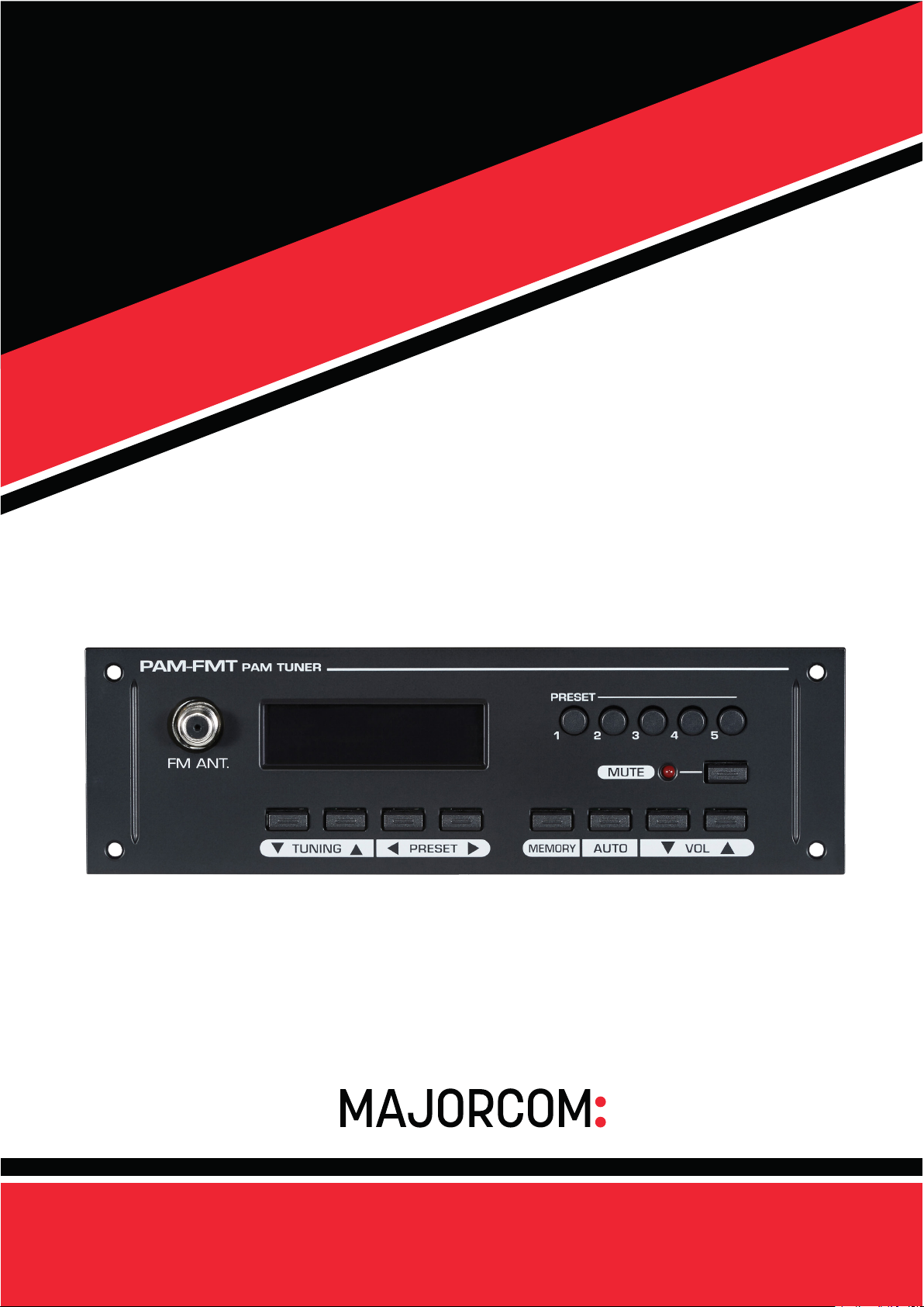
USER
MANUAL
PAM-FMT
Manual to download in PDF format on
www.majorcom.fr
Page 2
2
PAM-FMT PAM-FMT
3
Warning
CAUTION
RISK OF ELECTRIC SHOCK
DO NOT OPEN
CAUTION: TO REDUCE THE RISK OF ELECTRIC SHOCK.
DO NOT REMOVE COVER (OR BACK).
NO USER-SERVICEABLE PARTS INSIDE.
REFER SERVICING TO QUALIFIED SERVICE PERSONNEL.
WARNING
To prevent fire or shock hazard, do not expose the unit to rain or moisture.
This symbol is intended to alert the user to the presence of
uninsulated “dangerous voltage” within the product’s enclosure
that may be of sufficient magnitude to constitute a risk of electric shock to persons.
This symbol is intended to alert the user to the presence of important operation and maintenance (servicing) instructions in
the literature accompanying the appliance.
Caution: These servicing instructions are for use by qualified service person-
Attentions: Pour prévenir les chocs électriques ne pas utiliser cette fiche
*Do not install this equipment in a confined space such as a book case or
similar unit.
*The apparatus shall not be exposed to dripping or splashing and no objects
filled with liquids, such vases, shall be placed on the apparatus.
*Worded: “WARNING FOR YOUR PROTECTION PLEASE READ THE
FOLLOWING-WATER AND MOISTURE: Unit should not be used near
water(e.g. near a bathtub, washbowl, kitchen sink, laundry tub, in a wet
basement, or near a swimming pool, etc). Care should be taken so than
objects do not fall and liquids are not spilled into the enclosure through
openings.”
nel only. To reduce the risk of electric shock, do not any perform
any servicing other than that contained in the operating instructions
unless you are qualified to do so.
polarisée avec un prolongateur, une prise de courant on une
autre sortie de courant, sauf si les lames peuvent étre insérées
à fond sans en laisser aucune partie à découvert.
Contents
Welcome .............................................................................4
Unpacking ...........................................................................4
Installation
Environment.........................................................................5
Important Safety Instructions ...............................................5
Features ..............................................................................7
Contents and Accessories ..................................................7
Part Names and Function ...................................................8
How to Use the Tuner .......................................................10
Block Diagram...................................................................13
Specification......................................................................14
Service
Procedures ........................................................................15
Schematic ..........................................................................15
Parts List............................................................................15
Warranty ...............................................................................15
NOTE : This equipment has been tested and found to comply with the limits
for a Class A digital device, pursuant to Part 15 of the FCC Rules.
These limits are designed to provide reasonable protection against
harmful interference when the equipment is operated in a commercial environment. This equipment generates, uses, and can
radiate radio frequency energy and, if not installed and used in accordance with the instruction manual, may cause harmful interference to radio communications. Operation of this equipment in a
residential area is likely to cause harmful interference in which
case the user will be required to correct the interference at his own
expense.
* It can be heated up if you use this product in closed box or ill-ventilated place.
Usermanual V1.1 Usermanual V1.1
56, chemin de la Flambère · 31300 Toulouse · FRANCE · T é l . 3 3 (0)5 61 31 86 87
F a x 3 3 ( 0 ) 5 6 1 3 1 8 7 7 3 · [email protected] · www.majorcom.fr
56, chemin de la Flambère · 31300 Toulouse · FRANCE · T é l . 3 3 (0)5 61 31 86 87
F a x 3 3 ( 0 ) 5 6 1 3 1 8 7 7 3 · [email protected] · www.majorcom.fr
Page 3

4
PAM-FMT PAM-FMT
5
Welcome
A personal welcome to you from the management
and employees of Inter-M
All of the co-workers here at Inter-M are dedicated to
providing excellent products with inherently good
value, and we are delighted you have purchased
one of our products.
We sincerely trust this product will provide years
of satisfactory service, but if anything is not to your
complete satisfaction, we will endeavor to make
things right.
Welcome to Inter-M, and thank you for becoming
part of our worldwide extended family!
Unpacking
Please take a few minutes to read this manual to familiarize yourself with important information regarding installation, product features, and operation.
As with most electronic devices, ORIGINAL PACKAGING (OR EQUAL) IS REQUIRED in the unlikely event
that the product needs to be returned for servicing.
Installation
Environment
Never place this product in an environment which
could alter its performance or reduce its service life.
Such environments usually include high levels of heat,
dust, moisture, and vibration.
Important Safety Instructions
1. Read these instructions.
2. Keep these instructions.
3. Heed all warnings.
4. Follow all instructions.
5. Do not use this apparatus near water.
6. Clean only with dry cloth.
7. Do not block any ventilation openings. Install in accordance with the manufacturer’s instructions.
8. Do not install near any heat sources such as radiators, heat registers, stoves, or other apparatus (including amplifiers) that produce heat.
9. Do not defeat the safety purpose of the polarized or
grounding-type plug. A polarized plug has two
blades with one wider than the other. A grounding
type plug has two blades and a third grounding
prong. The wide blade or the third prong are provided for your safety. If the provided plug does not
fit into your outlet, consult an electrician for replacement of the obsolete outlet.
10. Protect the power cord from being walked on or
pinched particularly at plugs, convenience receptacles, and the point where they exit from the apparatus.
11. Only use attachments/accessories specified by
the manufacturer.
12. Use only with the cart, stand, tripod,
bracket, or table specified by the
manufacturer, or sold with the apparatus. When a cart is used, use
caution when moving the cart/ap-
S3125A
Usermanual V1.1 Usermanual V1.1
56, chemin de la Flambère · 31300 Toulouse · FRANCE · T é l . 3 3 (0)5 61 31 86 87
F a x 3 3 ( 0 ) 5 6 1 3 1 8 7 7 3 · [email protected] · www.majorcom.fr
56, chemin de la Flambère · 31300 Toulouse · FRANCE · T é l . 3 3 (0)5 61 31 86 87
F a x 3 3 ( 0 ) 5 6 1 3 1 8 7 7 3 · [email protected] · www.majorcom.fr
Page 4
6
PAM-FMT PAM-FMT
7
paratus combination to avoid injury from tip-over.
13. Unplug this apparatus during lightning storms or
when unused for long periods of time.
14. Refer all servicing to qualified service personnel.
Servicing is required when the apparatus has been
damaged in any way, such as power-supply cord or
plug is damaged, liquid has been spilled or objects
have fallen into the apparatus, the apparatus has
been exposed to rain or moisture, does not operate
normally, or has been dropped.
- AVOID EXCESSIVE HEAT, HUMIDITY, DUST AND VIBRATION
Keep the unit away from locations where it is likely to
be exposed to high temperatures or humidity-such as
near radiators, stoves, etc. Also avoid locations which
are subject to excessive dust accumulation, or to vibration that could cause mechanical damage.
- AVOID PHYSICAL SHOCKS
Strong physical shocks to the unit may cause damage.
Handle the unit with care.
- DO NOT OPEN THE CASE OR ATTEMPT REPAIRS
OR MODIFICATIONS YOURSELF
This product contains no user-serviceable parts. Refer
all maintenance to qualified Inter-M service personnel.
Opening the case and/or tampering with internal circuitry voids the warranty.
- ALWAYS POWER OFF BEFORE MAKING CONNECTIONS
Always turn the AC mains OFF before connecting or
disconnecting cables. This is important to prevent damage to the unit itself as well as other connected equipment.
- HANDLE CABLES CAREFULLY
Always plug and unplug cables (including the AC
mains power cord) by gripping the connector, not the
cord.
- CLEAN WITH A SOFT DRY CLOTH
Never use solvents such as benzine or paint thinner to
clean the unit. Wipe clean with a soft, dry cloth.
Features
MODULE FOR MOUNTING PAM SERIES
■
■
This is a module for mounting and is used with connecting to
PAM-SERIES.
SYSTEM INFORMATION VIA OLED DISPLAY
■
■
The system information can be checked through the OLED
display which is easy to operate.
40 TOTAL MEMORIES OF TUNER
■
■
40 total memory functions exist. It is possible to conveniently
memorize frequency of the desired broadcasting stations for
convenient use.
RADIO FREQUENCY AUTO SCAN FUNCTION
■
■
It is possible to automatically scan the radio frequency.
AUDIO VOLUME ADJUSTMENT AND MUTE FUNCTION
■
■
It is possible to adjust and mute the audio volume.
SLIDING MOUNTING METHOD (PAM-312/324/336/348)
■
■
It is convenient to install in PAM-Series by applying sliding
mounting method.
※ The PAM-510/520/120A/340A/480A systems are not sliding
mounting types. Open the top cover for this model and connect it with the inner connector.
※ It cannot be used in No.1 bay of PAM-120A.
Contents and Accessories
1. PAM-FMT x 1EA
2. Screws for PAM-Series x 4EA
3. Power and Audio Cable x 1EA
4. FM Antenna x 1EA
5. Operation Manual x 1EA
Usermanual V1.1 Usermanual V1.1
56, chemin de la Flambère · 31300 Toulouse · FRANCE · T é l . 3 3 (0)5 61 31 86 87
F a x 3 3 ( 0 ) 5 6 1 3 1 8 7 7 3 · [email protected] · www.majorcom.fr
56, chemin de la Flambère · 31300 Toulouse · FRANCE · T é l . 3 3 (0)5 61 31 86 87
F a x 3 3 ( 0 ) 5 6 1 3 1 8 7 7 3 · [email protected] · www.majorcom.fr
Page 5
8
1 3 42
8
765 9
PAM-FMT PAM-FMT
9
Part Names and Function
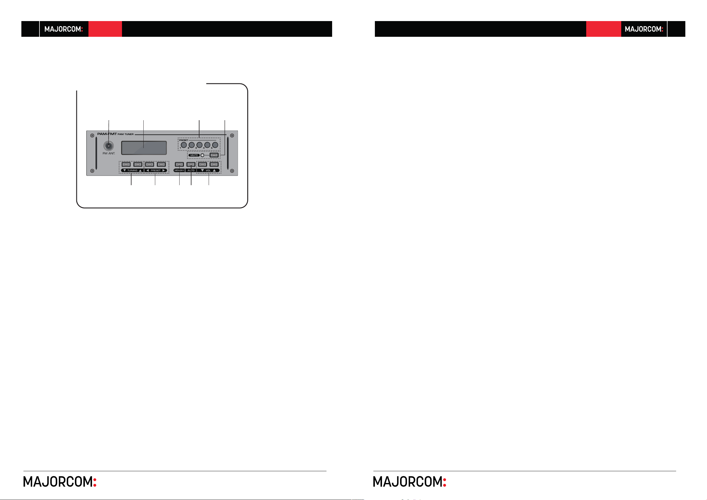
1. FM ANTENNA TERMINAL
This is a terminal to connect with FM antenna.
※ Decide the installation location and direction to make the
reception the best, and fix it firmly.
6. PRESET SELECTION BUTTON
These are buttons to browse saved PRESET. You can select
your desired PRESET from P01 to P40.
7. MEMORY BUTTON
This is a button to set PRESET.
※ For detailed information, refer to “How to Use the Tuner” on
page 10 of this manual.
8. AUTO BUTTON
This is a button to select the frequency automatically.
※ For detailed information, refer to “How to Use the Tuner” on
page 10 of this manual.
9. VOLUME BUTTON
This is a button to adjust the tuner volume. You can control the
volume between 0 and 100.
2. OLED DISPLAY
This is a window to display tuner operation information.
3. PRESET BUTTON
These are the buttons to call saved PRESET. You can call the
saved PRESET from 1 to 5.
4. MUTE BUTTON, STATUS LED
This is a button to mute the tuner. Press the button to turn on
the RED LED and mute the output. Press the button again to
turn off the LED and output the tuner sound source.
5. FREQUENCY TUNING BUTTON
This is a button to set the radio frequency as you wish by increasing or decreasing it.
Usermanual V1.1 Usermanual V1.1
56, chemin de la Flambère · 31300 Toulouse · FRANCE · T é l . 3 3 (0)5 61 31 86 87
F a x 3 3 ( 0 ) 5 6 1 3 1 8 7 7 3 · [email protected] · www.majorcom.fr
56, chemin de la Flambère · 31300 Toulouse · FRANCE · T é l . 3 3 (0)5 61 31 86 87
F a x 3 3 ( 0 ) 5 6 1 3 1 8 7 7 3 · [email protected] · www.majorcom.fr
Page 6
10
PAM-FMT PAM-FMT
How to Use the Tuner
1. HOW TO INSTALL THE MODULE
1) Turn off the PAM-Series amplifier before installation.
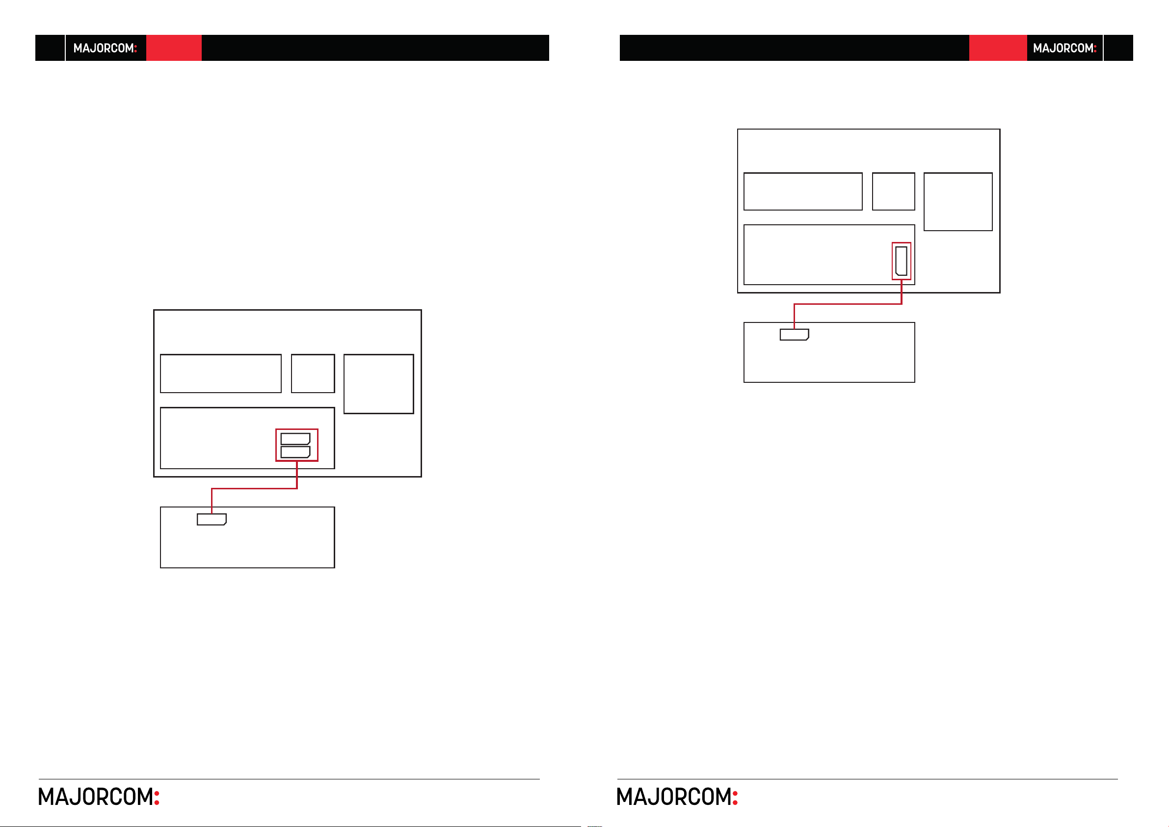
2) Connect the PAM-FMT module to the terminal of the PAMSeries main body using the enclosed 5-pin connector. Then,
slide the module into the slot until it is fully mounted. Terminal
information by product is as follows:
※ PAM-312/324 does not require an enclosed connector.
Slide the module all the way into the slot to connect the
internal connector to the module.
- PAM-340A/480A
- PAM-510/520
PAM-510/520
HEAT SINK
MAIN B’D
11
OPT
PT
CN_CD
PAM-340A/480A
HEAT SINK
MAIN B’D
CN10
CN7
CP701
PAM- FMT
OPT
CP701
PAM- F M T
PT
3) Fix the module by using the enclosed screw and turn on
the PAM-Series main body.
4) Turn on the device and check whether relevant module information is provided on the front OLED DISPLAY.
5) Adjust the volume appropriately and check whether the
sound source is output.
2. BROWSING RADIO FREQUENCY
1) Browsing Frequency
- Connect the enclosed FM antenna to the antenna con-
nection terminal.
- Press the FREQUENCY TUNING button to browse the
frequency above/below the currently displayed frequency and move to the radio frequency.
※ Each time you press the button, the frequency is
changed by 0.05 MHz(0.1MHz for Americas). You can
set the frequency from 87.5 MHz to 108 MHz.
- When the radio frequency is detected, TUNED is dis-
played in the upper-left area of the screen and the corresponding broadcast is output.
Usermanual V1.1 Usermanual V1.1
56, chemin de la Flambère · 31300 Toulouse · FRANCE · T é l . 3 3 (0)5 61 31 86 87
F a x 3 3 ( 0 ) 5 6 1 3 1 8 7 7 3 · [email protected] · www.majorcom.fr
56, chemin de la Flambère · 31300 Toulouse · FRANCE · T é l . 3 3 (0)5 61 31 86 87
F a x 3 3 ( 0 ) 5 6 1 3 1 8 7 7 3 · [email protected] · www.majorcom.fr
Page 7
12
MCU
EEPROM
Tuner Module Elec. Volume
I2C
I2C
Mute ctrl
OLED
IO Extender
SPI/Ctrl IO
Front key
+24VD
+24VA
+24VD
+24VA
20p connector for new PAM series
5p connector for old PAM series
Audio
PAM-FMT PAM-FMT
13
※ If there is a lot of noise in the radio frequency, adjust and
fix the antenna position appropriately.
2) Auto Scan
- Press the AUTO button to move to Auto Scan mode.
- When Auto Scan mode is activated, AUTO is displayed
in the upper-left area of the OLED DISPLAY.
- Press and hold the FREQUENCY TUNING button to automatically search for the best-received radio frequency
up/down the current radio frequency.
- When the search is completed, the current radio frequency is displayed and the broadcast is output.
- To deactivate Auto Scan mode, press the AUTO button
again.
3. USING THE PRESET FUNCTION
1) PRESET SETTING
- Search for the radio frequency to save.
- When the search is completed, press the MEMORY button to go to PRESET Setting mode.
- When PRESET Setting mode is activated, P is displayed
in front of the frequency and the relevant number is blinking.
- Press the PRESET button (1–5) to specify the PRESET
number to save.
※ You can save up to 40 numbers.
- If the PRESET number (P##) is one digit, specify your
desired number and press the MEMORY button to save
the PRESET. If the PRESET number is two digits, your
desired PRESET number is specified and saved at the
same time.
- When the saving process is completed, the message
PRESET SAVE OK appears on the OLED DISPLAY.
- Check the number in front of the current PRESET number (P##) to confirm whether the PRESET is correctly
set.
2) BROWSING AND CALLING PRESET
- Press the PRESET selection button to select your desired PRESET from P01 to P40.
- Press the PRESET button (1–5) to call the radio frequency of the saved PRESET.
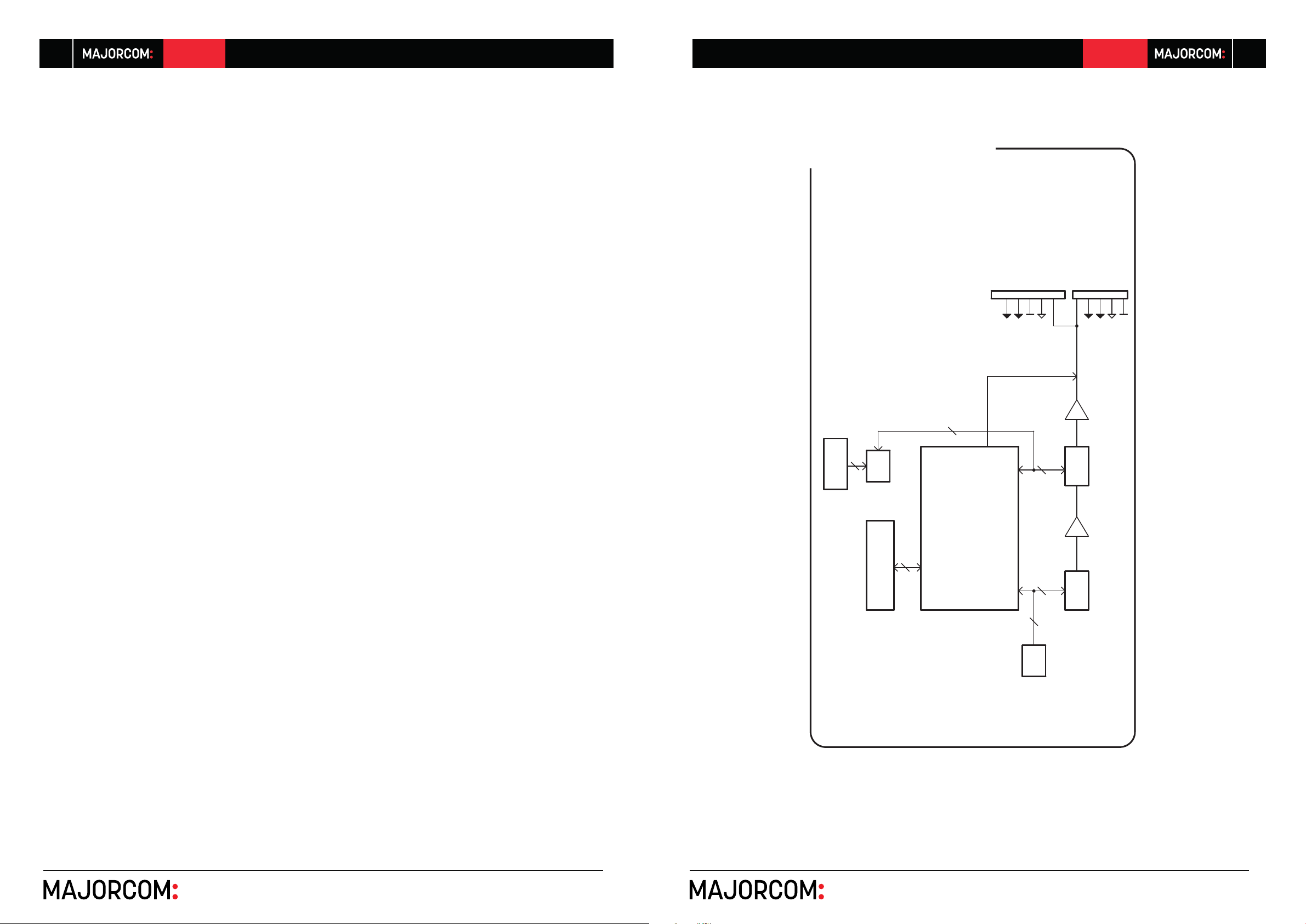
Block Diagram
Usermanual V1.1 Usermanual V1.1
56, chemin de la Flambère · 31300 Toulouse · FRANCE · T é l . 3 3 (0)5 61 31 86 87
F a x 3 3 ( 0 ) 5 6 1 3 1 8 7 7 3 · [email protected] · www.majorcom.fr
56, chemin de la Flambère · 31300 Toulouse · FRANCE · T é l . 3 3 (0)5 61 31 86 87
F a x 3 3 ( 0 ) 5 6 1 3 1 8 7 7 3 · [email protected] · www.majorcom.fr
Page 8
14
PAM-FMT PAM-FMT
15
Specification
PAM-FMT
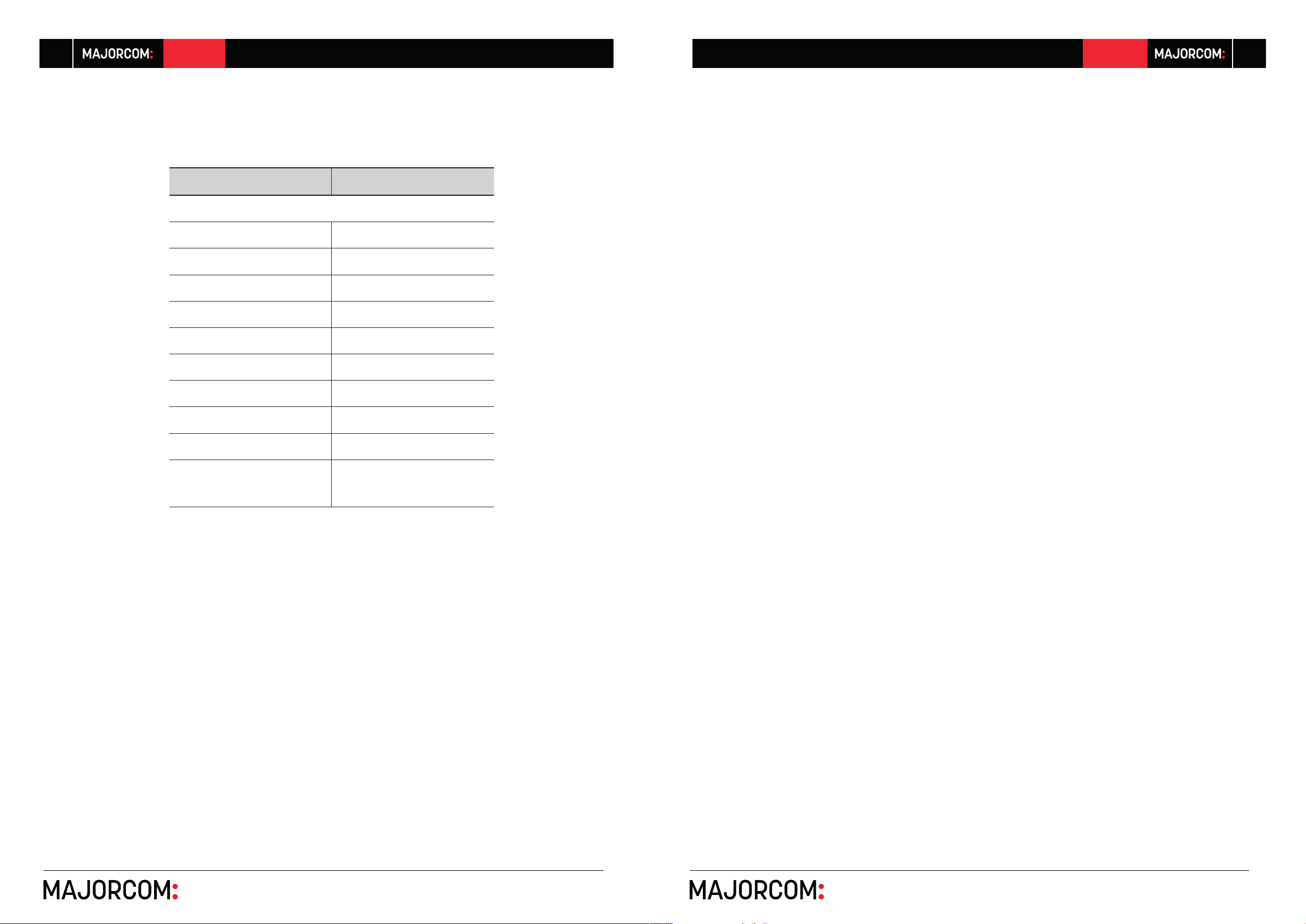
TUNER Specification
Receiving Frequency Range 87.5~108MHz
Antenna Input 75Ω Unbalanced
Frequency Response 50Hz~12KHz
THD + N (20KHz LPF) Less than 1%
S/N Ratio More than 60dB
Output Signal Level 0dBV ±3dBV
Operating temperature -10˚C~+40˚C
Power Source DC 24V
Weight(Set) 0.49kg/1.08lb
Service
Procedures
Ensure the problem is not related to operator error, or external system devices, Once it is certain that the problem
is related to the product contact your warranty provider as
described in the warranty section of this manual.
Schematic
A Schematic is available by contacting your warranty
provider.
Parts List
A Parts List is available by contacting your warranty
provider.
Dimensions(Set)
* Design and specification are subject to be changed for the improvement
of product quality without pre notice.
184(W) x 55(H) x 182(D)mm
7.24(W) x 2.16(H) x 7.16(D)in
Warranty
Warranty terms and conditions vary by country and may not
be the same for all products. Terms and conditions of warranty for a given product may be determined first by locating
the appropriate country which the product was purchased
in, then by locating the product type.
To obtain specific warranty information and available serv-
ice locations contact Inter-M directly or the authorized InterM Distributor for your specific country or region.
Usermanual V1.1 Usermanual V1.1
56, chemin de la Flambère · 31300 Toulouse · FRANCE · T é l . 3 3 (0)5 61 31 86 87
F a x 3 3 ( 0 ) 5 6 1 3 1 8 7 7 3 · [email protected] · www.majorcom.fr
56, chemin de la Flambère · 31300 Toulouse · FRANCE · T é l . 3 3 (0)5 61 31 86 87
F a x 3 3 ( 0 ) 5 6 1 3 1 8 7 7 3 · [email protected] · www.majorcom.fr
Page 9

PAM-FMT
User manual V1.1
56, chemin de la Flambère · 31300 Toulouse · FRANCE · T é l . 3 3 (0)5 61 31 86 87
F a x 3 3 ( 0 ) 5 6 1 3 1 8 7 7 3 · [email protected] · www.majorcom.fr
 Loading...