

Majorcom PA COM 13X5 User Manual
User Manual
www.majorcom.fr • commercial@majorcom.fr
Services techniques et commerciaux : 56, chemin de la Flambère - 31300 TOULOUSE (France) • Tel. +33 (0)5 61 31 86 87 • Fax. +33 (0)5 61 31 87 73
Siège Social : RN 307 - 78810 FEUCHEROLLES • S.A. Capital 80.000 € • SIRET 334 579 869 000 28 • NAF 4652 Z • TVA Intracommunautaire FR 12334579869
MAJORCOM \ QUALITE \ ENREGISTREMENT DES DOCUMENTS \ ADMINISTRATIF \ ENR-12-PEM-V02
USER MANUAL
PRE-AMPLIFICATION
ROUTING SYSTEM
PA COM 13X5
User Manual
www.majorcom.fr • commercial@majorcom.fr
Services techniques et commerciaux : 56, chemin de la Flambère - 31300 TOULOUSE (France) • Tel. +33 (0)5 61 31 86 87 • Fax. +33 (0)5 61 31 87 73
Siège Social : RN 307 - 78810 FEUCHEROLLES • S.A. Capital 80.000 € • SIRET 334 579 869 000 28 • NAF 4652 Z • TVA Intracommunautaire FR 12334579869
MAJORCOM \ QUALITE \ ENREGISTREMENT DES DOCUMENTS \ ADMINISTRATIF \ ENR-12-PEM-V02
I Functions
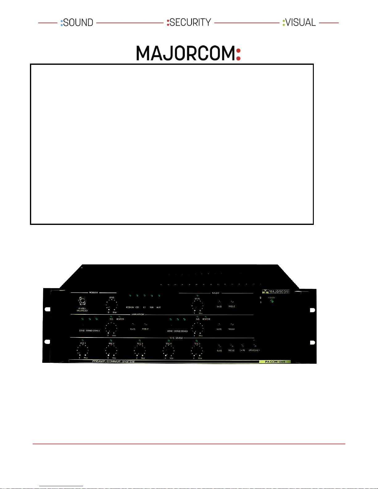
The PA COM 13X5 is a pre-amplification and routing system designed for use in public address systems in
public, commercial and leisure areas.
It is equipped with:
a high priority safety input
5 adjustable priority microphone inputs which enable the connection of 5 microphones and the routing of
announcements across 5 selected areas. A dual band equaliser allows the optimisation of the sound
broadcast.
2 AUX inputs (music) with adjustable level and switchable.
An event/podium input with adjustment dial of input level (0 to 60dB), adjustable manual or automatic
remote control, switches that allow the independent configuration of these inputs across each speaker areas,
and a bass/treble correction for each input
2 inputs for wireless microphone equipped with a trim potentiometer permitting the input’s gain from 0 dB
to –60 dB, a manual or automatic adjustable remote control, switches that can assign these inputs
independently on the first 3 areas, and a bass / treble correction for each input.
Possibility to insert advertising messages during music (LECT. PUB. optional)
Electronic chime for the pre-announcement of microphone calls
The presence of modulation on each source is signalled by LED.
Can be operated on a 24V DC emergency power supply.
II Configuration
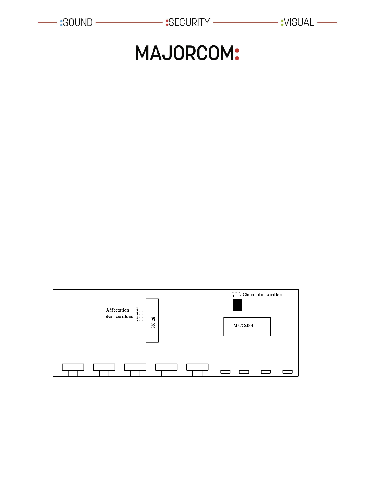
The chime can be removed from some microphones, if required. For this, remove the jumpers corresponding to
the microphone where the chime is not required. This configuration is made on the micro card, reference CI 02
7.
You can also choose between two chimes. To do this, move the jumper that is situated close to the memory
M27C4001. The jumpers are tracked down in the following way:
User Manual
www.majorcom.fr • commercial@majorcom.fr
Services techniques et commerciaux : 56, chemin de la Flambère - 31300 TOULOUSE (France) • Tel. +33 (0)5 61 31 86 87 • Fax. +33 (0)5 61 31 87 73
Siège Social : RN 307 - 78810 FEUCHEROLLES • S.A. Capital 80.000 € • SIRET 334 579 869 000 28 • NAF 4652 Z • TVA Intracommunautaire FR 12334579869
MAJORCOM \ QUALITE \ ENREGISTREMENT DES DOCUMENTS \ ADMINISTRATIF \ ENR-12-PEM-V02
III Connections
1) Connect the power supply (21).
2) Connect the 24V DC safety supply on terminals (29). The + to red and the - to black.
The device should be turned on during the connection of the batteries.
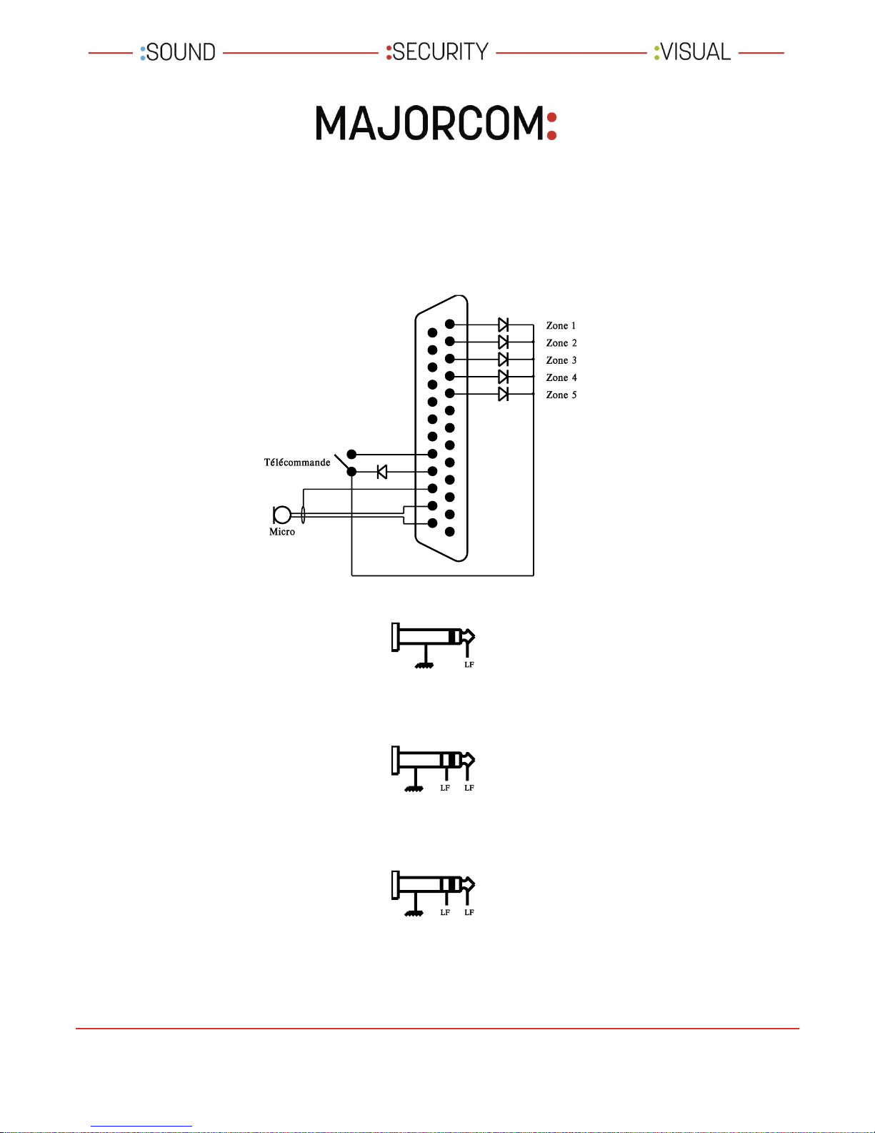
3) Connect the sub-d 25 point plug coming from a desk microphone (such as MAGPX 5) to the input (20). The
use of a 6/10, 5 pair phone shielded cable is advised. If the use of another type of microphone is required
connect the diodes on the areas where this microphone should broadcast, as follows:
4) Connect the music sources: CD, tape, radio, and the event podium AUX on a 6.35mm jack as follows:
An event podium can make a balanced connection on the rear panel (19) for permanent installation or on the
front panel (1) for temporary installation. The connection of a plug in the front socket (1) automatically
disconnects the rear.
This source must be equipped with a balanced output. If not, a 600 / 600 transformer will be required.
5) Connection of wireless event podium to 6.35 mm jack (22):
This input is balanced and must be wired as follows:
If your wireless system supplies a remote control by dry contact, link this remote to the terminal (26) and put
switch (27) to Ext. Rem.
There are two independent H.F. inputs. Proceed in the same way for the second input.
6) Connect the emergency player to the 6.35 mm jack (31) as follows (unbalanced input):
 Loading...