

Majorcom digiPRO 1200, digiPRO 2800, digiPRO 4800, digiPRO 2250, digiPRO 6800 Operating Manual
...Page 1
Operating Manual
( Manuel d’utilisation )
digiPRO - 1200
2800
4800
6800
2250
2500
4120
4240
VA- SERIES
Page 2

Page 3

• Avant usage ........................................................................................................................................................... 04
• Caractéristiques ....................................................................................................................................................... 04
• Précautions d’emploi ......................................................................................................................................... 05
• Fonctions façade avant .................................................................................................................................. 06
• Fonctions façade arrière .................................................................................................................................. 08
• Schéma Bloc .......................................................................................................................................................... 10
• Spécificités ............................................................................................................................................................ 12
Sommaire
3
Page 4
4
Merci de lire ce manuel attentivement avant usage pour garantir un bon usage du produit.
Attention, le produit peut être endommagé si :
· Le produit est exposé à une source de chaleur ou à l’humidité
· Le produit n’est pas utilisé dans un endroit ventilé et à l’abri de la poussière
· Amplificateur de type classe D à haut rendement (plus de 85%)
· Produit rackable de faible encombrement (1U)
· Alimentation AC/DC de technologie SMPS permettant de fournir une puissance élevée sur un faible
encombrement
· Il peut fonctionner sur batterie en cas de coupure secteur
· Sortie 70 et 100V sans transformateur
Avant usage
Caractéristiques
1
2
Page 5
5
· Ne pas réparer, démonter, altérer le produit
· Ne pas utiliser le produit avec les mains mouillées
· Ne pas installer le produit à un endroit poussiéreux ou humide (Risque d’électrocution)
· Ne pas nettoyer le produit à l’eau
· Nettoyer le produit avec un chiffon sec. Ne pas utiliser de produits chimiques ou détergents
· Quand vous vérifiez la sortie d’alimentation avec des instruments de mesure, il faut connecter le
filtre passe bas 20kHz sur la sortie
· Ne pas connecter d’instruments de mesure sur la sortie directement
· Brancher le prise d’alimentation fermement, ne pas tremble. Risque d’inflammation si mal branché
· Ne rien insérer de métallique dans les aérations. Risque d’inflammation et d’électrocution
· Installer le produit dans une pièce ventilée
· Ne pas installer à proximité d’une source de chaleur
· Ne pas jeter ou donner des coups au produit
· S’il y a de la fumée ou que vous sentez une odeur, il faut stopper l’utilisation immédiatement
Si tel est ma cas, mettre l’appareil hors tension, débrancher le et contacter votre service client
· Bien qu’il y ait une protection coupe circuit, attention que le plus et moins ne soit pas en court circuit.
If you want to dispose of this product, do not mix with general househole waste. There are
serarate collection systems for used electronic products in accordance with legislation under
the WEEE Directive (Directive 2002/96/EC) and is effective only within the European Union.
Précautions
2. Attention
1. Attention
3
Page 6
6
4
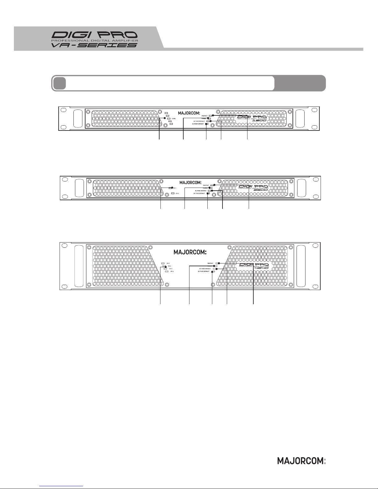
Fonctions façade avant
① ② ③④⑤
① ② ③④⑤
① ② ③④⑤
Page 7

7
Ce bargraphe à Leds indique le niveau sonore.
Quand le signal est supérieur à 0DB, la LED s’allume en jaune.
2. Led En Service
4. Led Défaut fusible AC
5. Led Défaut fusible DC
3. Led Mise en protection
1. Bargraphe de Modulation
Si quelque chose d’anormal se produit (court circuit, surtension, surchauffe…), l’amplificateur cessera de
fonctionner et la LED de protection s’allumera. Une fois le problème régler, l’amplificateur fonctionnera.
Quand la LED est allumée, ceci signifie que le fusible AC est hors service.
Quand la LED est allumée, ceci signifie que le fusible DC est hors service.
Quand cette LED est allumée, cela signifie que le système d’alimentation de l’amplificateur fonctionne
bien L’amplificateur fonctionne de manière optimale.
4
Fonctions façade avant
Page 8
8
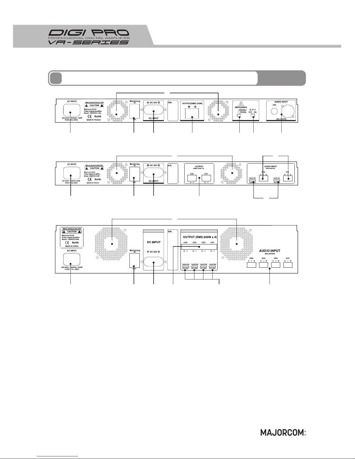
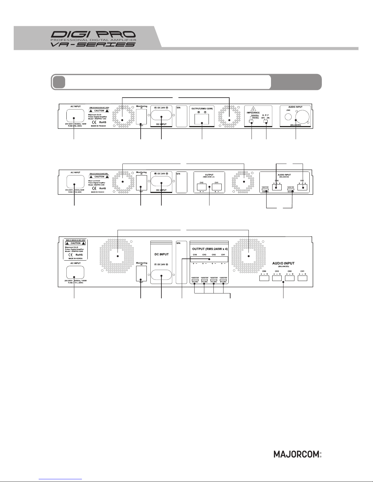
Prise Secteur AC 200~240V, 50/60Hz
1. Prise Secteur
2. V entilateurs
3. Monitoring
Les aérations rejettent la chaleur générée par le fonctionnement du produit. Ne pas les obstruer
.
C’est la synthèse de défaut. Un contact sec normalement fermé entre la PIN 1 du connecteur IN et la PIN
1 du connecteur OUT donne l’information sur l’état des fusibles AC et DC. Si un des deux fusibles est hors
service, le contact sera ouvert. Les connecteur IN et OUT permettent de mettre en série très facilement les
synthèses de défaut de plusieurs amplificateurs.
5
Fonctions façade arrière
① ③ ④ ⑤
② ⑦
⑥
⑧① ③ ④ ⑤ ⑥ ⑦
②
① ③ ④ ⑤ ⑥ ⑦
②
Page 9

9
4. Connecteur Alimentation 24Vdc
Connecteur Alimentation 24Vdc; Vérifier la polarité avant la connexion.
5. Sortie Vers Ligne HP
Connecteur de sortie Ligne vers les haut Parleur. Vérifier la polarité avant de connecter la ligne.
Attention de ne pas connecter une impédance inférieure à celle supportée par l’amplificateur.
5
Fonctions façade arrière
Connecteur d’entrée de l’amplificateur. Cette entrée est en 0dB symétrique.
7. Connecteur d'entrée de modulation
6. SELECTEUR D’IMPEDANCE DE SORTIE
70V SWITCH POSITION
DIGIPRO 1200 MODEL : 40 Ω
DIGIPRO 2800 MODEL : 17 Ω
DIGIPRO 4800 MODEL : 10 Ω
DIGIPRO 6800 MODEL : 8 Ω
DIGIPRO 2250 MODEL : 20 Ω
DIGIPRO 2500 MODEL : 10 Ω
DIGIPRO 4120 MODEL : 41 Ω
DIGIPRO 4240 MODEL : 20 Ω
Ne pas changer la position du sélecteur d’impédance en cours d’utilisation.
Impédances HP minimales
100V SWITCH POSITION
DIGIPRO 1200 MODEL : 83 Ω
DIGIPRO 2800 MODEL : 35 Ω
DIGIPRO 4800 MODEL : 20 Ω
DIGIPRO 6800 MODEL : 15 Ω
DIGIPRO 2250 MODEL : 40 Ω
DIGIPRO 2500 MODEL : 20 Ω
DIGIPRO 4120 MODEL : 83 Ω
DIGIPRO 4240 MODEL : 41 Ω
Bouton ON/OFF pour active le Filtre Passe haut. La fréquence de coupure à -3dB est de 300Hz.
8. HPF Filtre Passe Haut
Page 10
10
6
INPUT
BALANCED
H
C
G
OVER CURRENT P/T
FE T
SHORT P/T
IM PEDAN CE
MA TCHIN G
AU DIO L EVEL METE R
+VBB
PWM
DRIVER
A.L.C
H. P.F
H.P.F S/W
TEMPERATURE P/T
PWM
DRIVER
+VBB
FE T
IM PEDAN CE
SE LETOR
FE T
FE T
-V EE
B. AMP
-VEE
INPUT : 200 Vac ~ 240 Vac
F/G
EMI FILTER
ACTIVE INRUSH
CURRENT
LIMITING
ISOLATED
TRANSFORM
+85VDC
-85VDC
CURRENT SENSING
RECTIFIERS
&
FILTER
PWM
MAIN SWITCHING
RECIFIERS
& P.F.C
POWER
SWITCHING
ISOLATED
TRANSFOMER
RECTIFIERS
AC/N
AC/L
REMOT CONTROL
FAN LOCK &
PROTECTION
FEED BACK CONTROL
DETECTING
CIRCUIT
O.V.P / D.T.P
REMOT CONTROL
P.F.C / PWM
CONTROL
BATTERY ( + )
MAIN
SWITCHING
BATTERY ( - )
+12 V
-12 V
FAN
AUXI Liary
FEED BACK CONTROL
O.V.P/O.C.P
&
P.W.M
Amplificateur Numérique Professionnel
AC/ DC SMPS
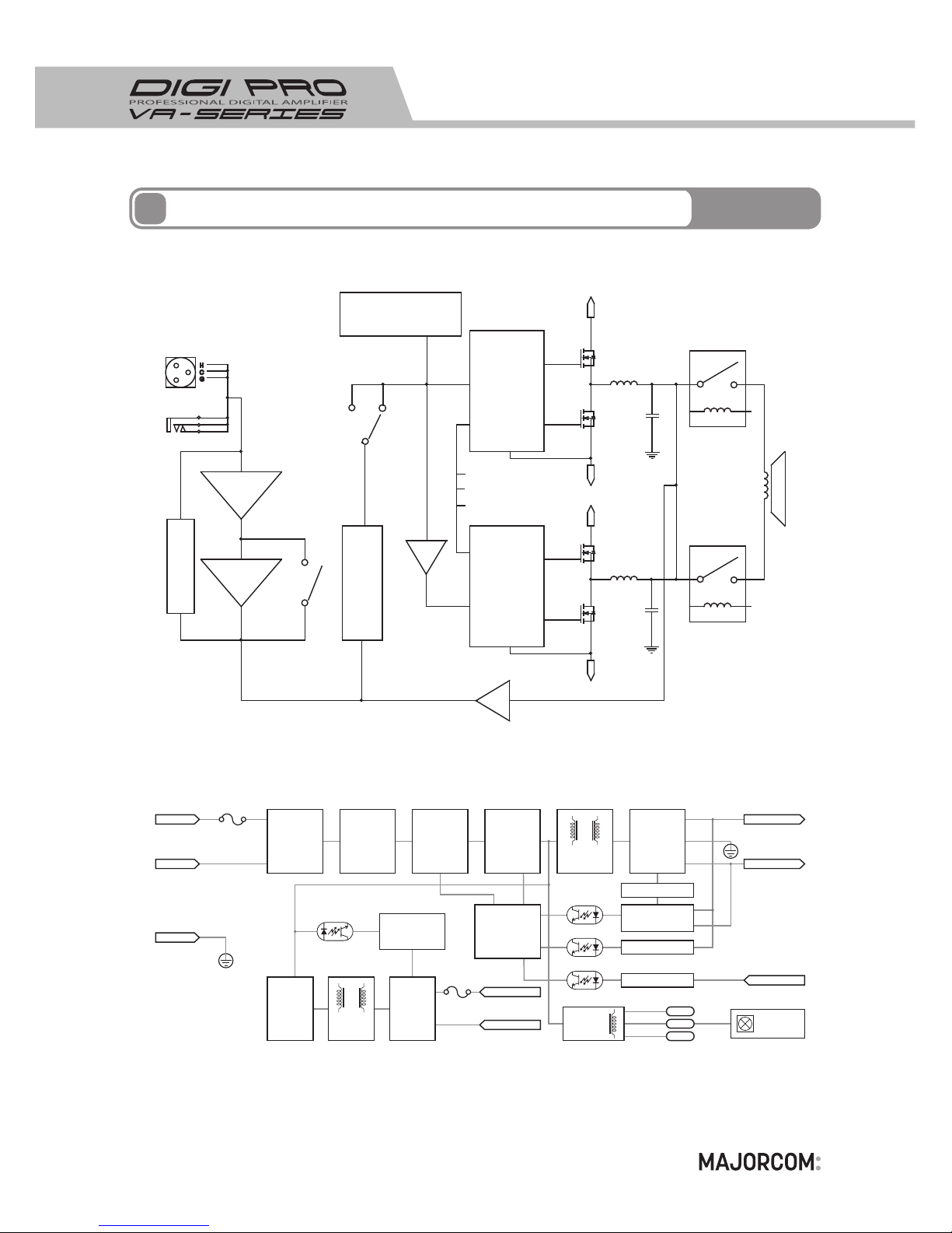
Schema Bloc (1CH)
Page 11
11
6
INPUT
H
C
G
OVER CURRENT P/T
FE T
SHORT P/T
IM PEDAN CE
MA TCHIN G
AU DIO L EVEL METE R
+VBB
PWM
DRIVER
A.L.C
TEMPERATURE P/T
PWM
DRIVER
+VBB
FE T
IM PEDAN CE
SE LETOR
FE T
FE T
-V EE
B. AMP
-VEE
INPUT : 200 Vac ~ 240 Vac
F/G
EMI FILTER
ACTIVE INRUSH
CURRENT
LIMITING
ISOLATED
TRANSFORM
+85VDC
-85VDC
CURRENT SENSING
RECTIFIERS
&
FILTER
PWM
MAIN SWITCHING
RECIFIERS
& P.F.C
POWER
SWITCHING
ISOLATED
TRANSFOMER
RECTIFIERS
AC/N
AC/L
REMOT CONTROL
FAN LOCK &
PROTECTION
FEED BACK CONTROL
DETECTING
CIRCUIT
O.V.P / D.T.P
REMOT CONTROL
P.F.C / PWM
CONTROL
BATTERY ( + )
MAIN
SWITCHING
BATTERY ( - )
+12 V
-12 V
FAN
AUXI Liary
FEED BACK CONTROL
O.V.P/O.C.P
&
P.W.M
Amplificateur Numérique Professionnel
AC/ DC SMPS
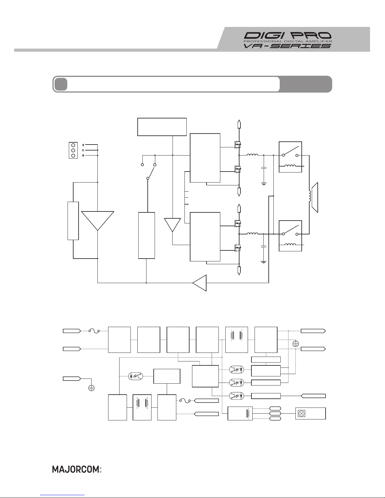
Schema Bloc (2CH / 4CH)
Page 12
12
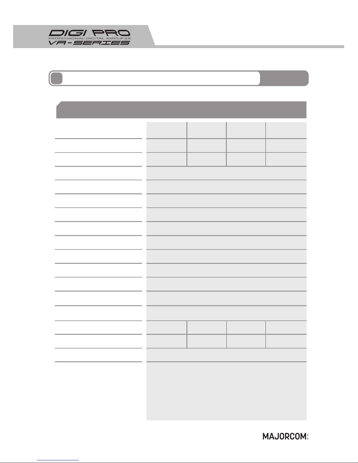
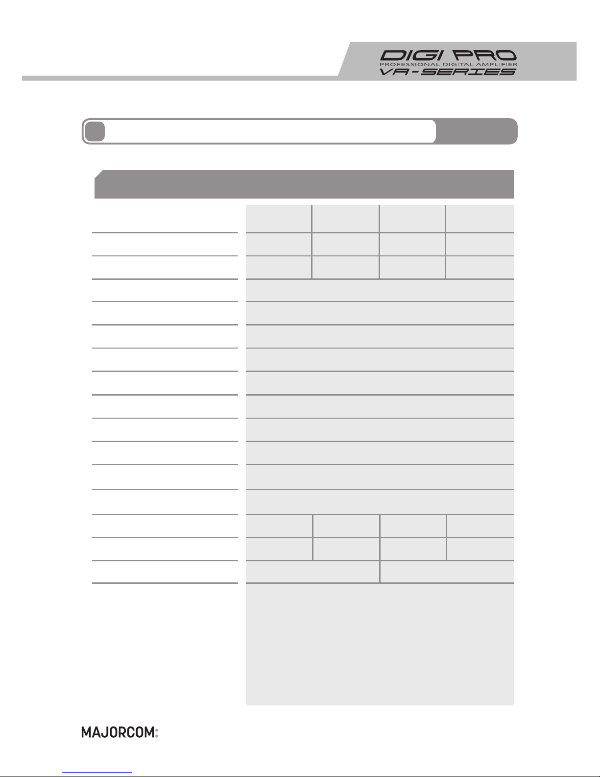
Gamme de Puissance RMS
Modele
Impédance de Sortie (70/100V)
Bande Passante (-3dB/OCT)
Filtre Passe Haut d'entrée
Dynamique
Rapport S/N
Poids
Dimensions (LxHxP)
Circuit de Protection
T.H.D (RMS)
Niveau d'entrée
Rendement
Alimentation Secteur/ Fréquence
Alimentation de secours DC
Température ambiante
Humidité ambiante
Puissance consommée
480 W 680 W280 W120 W
17Ω/35Ω40Ω/83Ω 8Ω/15Ω10Ω/20Ω
20 Hz ~ 20 KHz
> 100 dB
300 Hz
> 100 dB
< 1 %
483 (W) x 44 (H) x 340 (D) mm 1U (avec les poignes)
Protection contre les surcharges
Protection Thermique
Protection contre les court circuits sur la ligne
Protection contre les tensions continues en sortie
Coupure modulation lors de la mise sous tension
Protection sur-consommation AC
1.0 ~ 5.0 V rms
85 %
AC 200 ~ 240V / 50, 60 Hz
DC 22 ~ 28 V
- 10 ~ 40
℃
~ 95%
620 W
340 W160 W 750 W
5 Kg5 Kg5 Kg
6 Kg
Spécificités
7
DIGIPRO 2800DIGIPRO 1200 DIGIPRO 4800 DIGIPRO 6800
Caractéristiques
Page 13
13
Gamme de Puissance RMS
Modele
Impédance de Sortie (70/100V)
Bande Passante (-3dB/OCT)
Dynamique
Rapport S/N
Poids
Dimensions (LxHxP)
Circuit de Protection
T.H.D (RMS)
Niveau d'entrée
Rendement
Alimentation Secteur/ Fréquence
Alimentation de secours DC
Température ambiante
Humidité ambiante
Puissance consommée
2 X 500 W 4 X 240 W2 X 250W 4 X 120W
20Ω / 40Ω 41Ω / 83Ω10Ω / 20Ω 20Ω / 41Ω
20 Hz ~ 20 KHz
> 100 dB
> 100 dB
< 1 %
483 (W) x 44 (H) x 340 (D) mm
1U (avec les poignes)
483 (W) x 88 (H) x 340 (D) mm
2U (avec les poignes)
Protection contre les surcharges
Protection Thermique
Protection contre les court circuits sur la ligne
Protection contre les tensions continues en sortie
Coupure modulation lors de la mise sous tension
Protection sur-consommation AC
1.0 ~ 5.0 V rms
85 %
AC 200 ~ 240V / 50, 60 Hz
DC 22 ~ 28 V
- 10 ~ 40
℃
~ 95%
1250 W 1200 W
625 W 650 W
8 Kg 10 Kg7 Kg 9 Kg
Spécificités
7
DIGIPRO 2250 DIGIPRO 4120DIGIPRO 2500 DIGIPRO 4240
Caractéristiques
Page 14

Page 15

• Beforeinstallingequipments....................................................................16
• Features..................................................................................................16
• ImportantPrecautions..............................................................................17
• FunctionsofFrontPanel............................................................................18
• FunctionsofRearPanel............................................................................20
• BlockDiagram........................................................................................22
• Specifications........................................................................................24
contents
15
Page 16
16
Please read this manual carefully from beginning to end before you use for the best performance and correct use of this product.
Please be careful that it may cause the failure of this product if you install in the following
places.
· A place which is exposed to direct sunlight or near to heating units such as steam,
heater and stove .
· A place of bad ventilation or lot of dusts.
· High Efficiency Digital Class-D Amplifier with efficiency rate more than 85%.
· You can install in the narrow space by 1U small size.
· It supplies large output power source by AC/DC SMPS with small and light size.
· It can be operated by DC batteries in the time of power outage or emergency.
· You can use High Voltage (70V/100V) output without transformer.
Beforeinstallingequipments
Features
1
2
Page 17
17
· Do not repair disassembled parts or do not alter the product.
· Do not operate the product with wet hands. (It may cause electric shock.)
· Do not install the product in the place where there is a lot of moisture and dust.
(It may cause the fire or electric shock.)
· Do not sprinkle water on the parts of the product when you clean.
Wipe exterior surface with a dry cloth lightly. Do not use chemicals or detergents.
· When you check the output power by using the measuring instrument, please connect
the 20KHz low-pass filter with the output terminal.
· Do not connect any measuring instruments with the output terminal directly
(If you want to check the output, please connect the ground with the plus output terminal
and the ground with the minus output terminal)
· Please insert the power plug firmly not to be shaken.
(It may cause the fire if it is not connected completely.)
· Do not insert or drop the metalware (coins, hairpins or irons etc.) into the ventilation holes.
(It may cause the fire or electric shock.)
· Please install the product in a well ventilated place.
· Do not install the product in the place where there are heating equipments or heat.
· Do not drop something or give impact to the product.
· If the smoke arises or you smell the strange odors, stop the operation of the product.
In this case, turn off the power and pull the plug out of the socket and contact service
center.
· Although there is the embedded protection circuit, please be careful of a short causing
the connection between plus output terminal and minus output terminal.
ImportantPrecautions
2.Caution
1.Warning
3
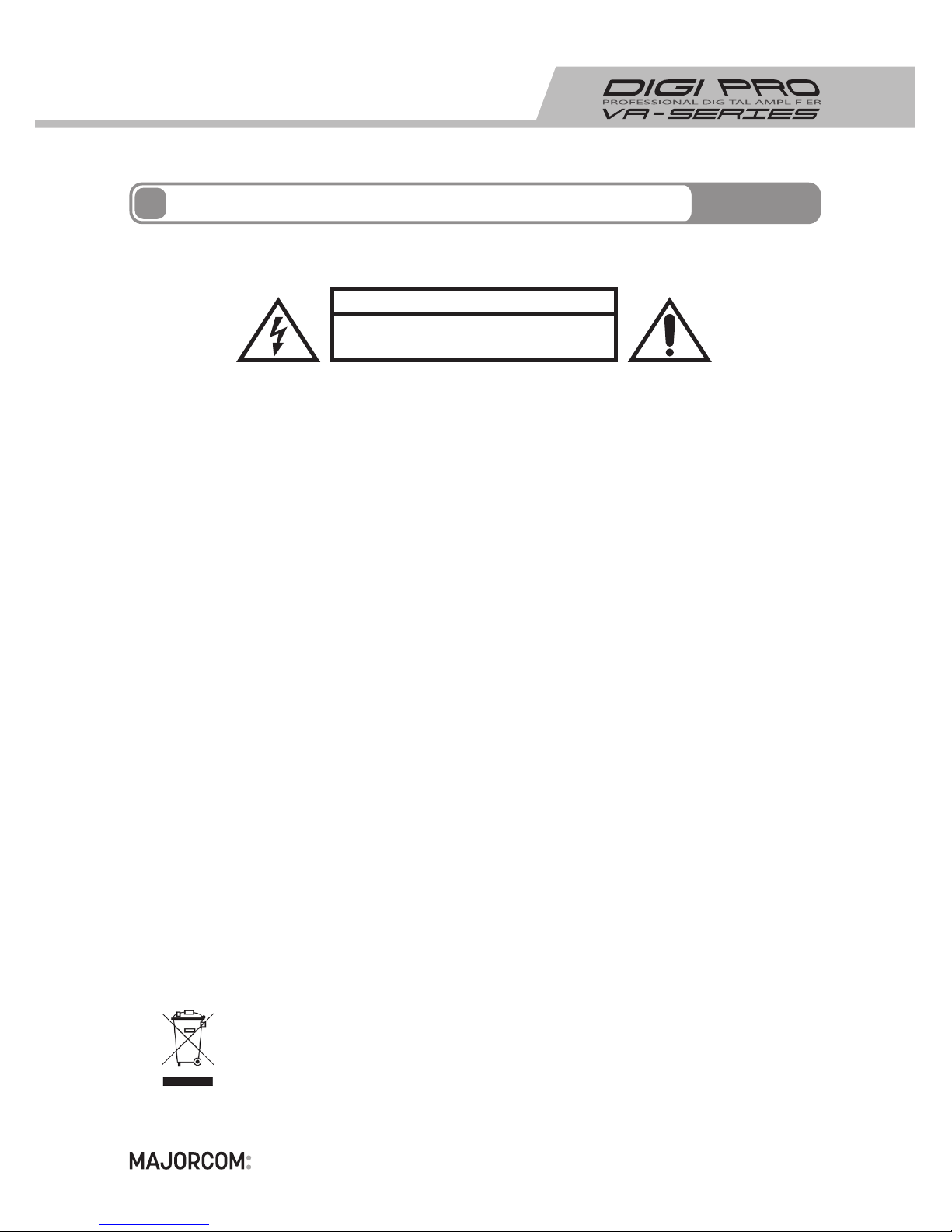
CAUTION
RISK OF ELECTRONICS SHOCK
DO NOT OPEN
If you want to dispose of this product, do not mix with general househole waste.
There are serarate collection systems for used electronic products in accordance
with legislation under the WEEE Directive (Directive 2002/96/EC) and is effective
only within the European Union.
Page 18
18
4
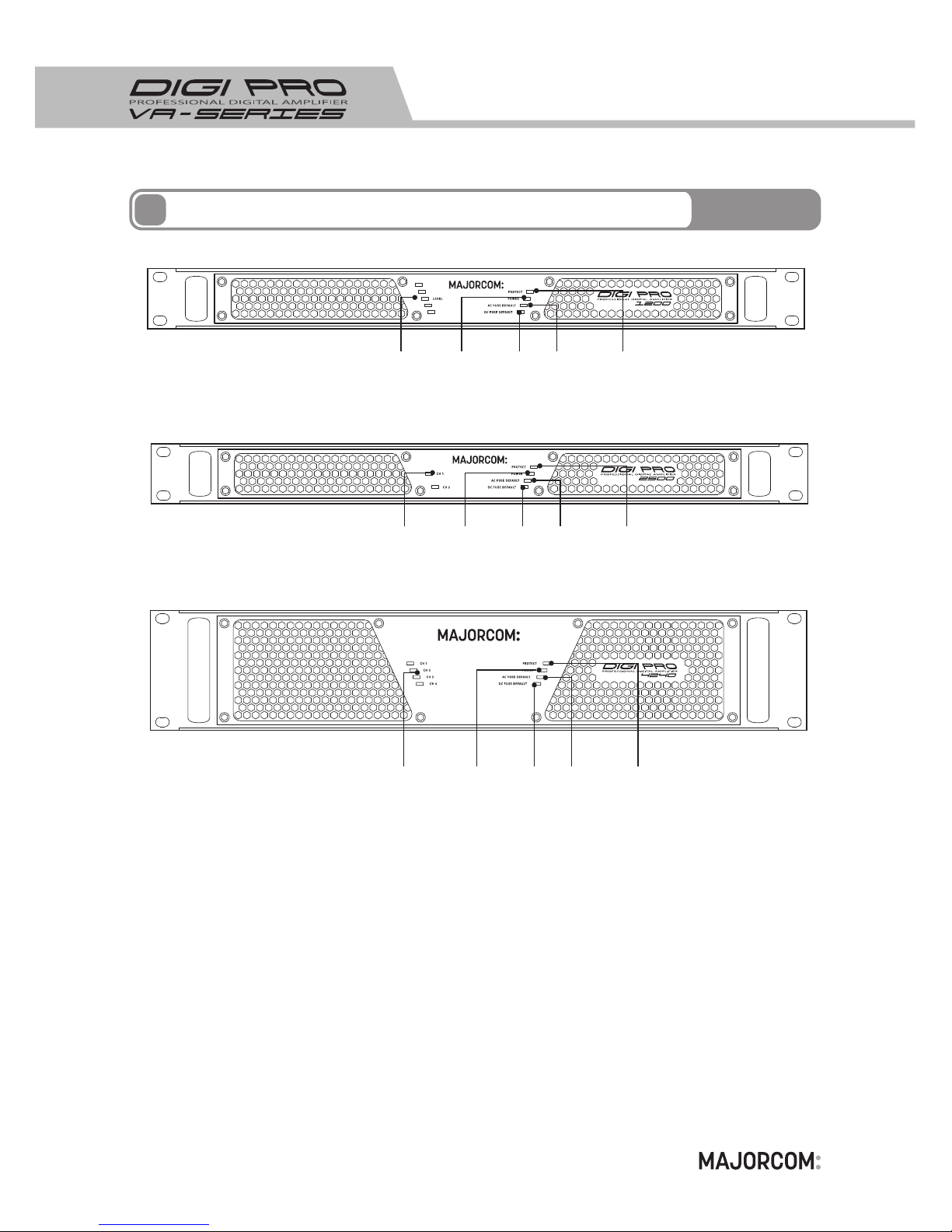
FunctionsofFrontPanel
① ② ③④⑤
① ② ③④⑤
① ② ③④⑤
Page 19

19
This LED shows the input level of sound source and will be lit depends on input level.
When signal up to 0dB, the yellow LED will be lit.
2.POWERLED
4.ACFUSEDEFAULTLED
5.DCFUSEDEFAULTLED
3.PROTECTLED(PROTECTDISPLAY)
1.LEVELLED(INPUTLEVEL)
If there are something wrong such as Short of Speaker Line, Overcurrent or Overheat, working of amplifier will be stopped and Protect LED will be lit. Once the problem is solved, the
amplifier will work normally.
When this LED is on, it means AC fuse is broken or removed.
When this LED is on, it means DC fuse is broken or removed.
When this LED is on, it means the main power supply system of amplifier is working and
the amplifier works without any problems.
4
FunctionsofFrontPanel
Page 20
20
AC Power Jack: AC 200~240V, 50/60Hz
1.ACInlet(ACPowerInput)
2.FanMotor(AirVent)
3.MONITORING
Air Vent to release the heat generated inside the product. Please be careful not to block
the vent area.
This is the synthesis Default. A dry contact normally closed between Pin 1 IN connector
and Pin 1 OUT connector gives information about AC and DC fuses. When DC or AC fuse
is broken, this contact will be open. IN and OUT connectors permit to link easily several
amplifiers to have a general synthesis default.
5
FunctionsofRearPanel
① ③ ④ ⑤
② ⑦
⑥
⑧① ③ ④ ⑤ ⑥ ⑦
②
① ③ ④ ⑤ ⑥ ⑦
②
Page 21

21
4.DCBatteryJACK(EMERGENCYPOWERDC24VINPUT)
Supplementary Battery to be used supplying DC24V. Please connect after checking +, polarity
5.SPEAKEROUTPUTJACK(AMPOUTPUTJACK)
Please connect Amplifier Output Jack after checking +, - polarity.
Please be careful not to connect less than rating impedance.
5
FunctionsofRearPanel
This connector is to connect the pre-amplifier.
7.AUDIOINPUTCONNECTOR
6.OUTPUTIMPEDANCESWITCH(IMPEDANCESELECTIONSWITCH)
70V SWITCH POSITION
DIGIPRO 1200 MODEL : 40 Ω
DIGIPRO 2800 MODEL : 17 Ω
DIGIPRO 4800 MODEL : 10 Ω
DIGIPRO 6800 MODEL : 8 Ω
DIGIPRO 2250 MODEL : 20 Ω
DIGIPRO 2500 MODEL : 10 Ω
DIGIPRO 4120 MODEL : 41 Ω
DIGIPRO 4240 MODEL : 20 Ω
Speaker Load Connection Use.
Do not change impedance selection switch while the amplifier is working.
100V SWITCH POSITION
DIGIPRO 1200 MODEL : 83 Ω
DIGIPRO 2800 MODEL : 35 Ω
DIGIPRO 4800 MODEL : 20 Ω
DIGIPRO 6800 MODEL : 15 Ω
DIGIPRO 2250 MODEL : 40 Ω
DIGIPRO 2500 MODEL : 20 Ω
DIGIPRO 4120 MODEL : 83 Ω
DIGIPRO 4240 MODEL : 41 Ω
Speaker Load Connection Use.
If you make position the Filter as「ON」, degree of voice clearing will be improved by at
tenuation of -3dB/Octave under less than 300Hz.
8.HPF(HIGH-PASSFILTER)
Page 22
22
6
INPUT
BALANCED
H
C
G
OVER CURRENT P/T
FE T
SHORT P/T
IM PEDAN CE
MA TCHIN G
AU DIO L EVEL METE R
+VBB
PWM
DRIVER
A.L.C
H. P.F
H.P.F S/W
TEMPERATURE P/T
PWM
DRIVER
+VBB
FE T
IM PEDAN CE
SE LETOR
FE T
FE T
-V EE
B. AMP
-VEE
INPUT : 200 Vac ~ 240 Vac
F/G
EMI FILTER
ACTIVE INRUSH
CURRENT
LIMITING
ISOLATED
TRANSFORM
+85VDC
-85VDC
CURRENT SENSING
RECTIFIERS
&
FILTER
PWM
MAIN SWITCHING
RECIFIERS
& P.F.C
POWER
SWITCHING
ISOLATED
TRANSFOMER
RECTIFIERS
AC/N
AC/L
REMOT CONTROL
FAN LOCK &
PROTECTION
FEED BACK CONTROL
DETECTING
CIRCUIT
O.V.P / D.T.P
REMOT CONTROL
P.F.C / PWM
CONTROL
BATTERY ( + )
MAIN
SWITCHING
BATTERY ( - )
+12 V
-12 V
FAN
AUXI Liary
FEED BACK CONTROL
O.V.P/O.C.P
&
P.W.M
DIGITAL PROFESSIONAL AMP
AC/ DC SMPS
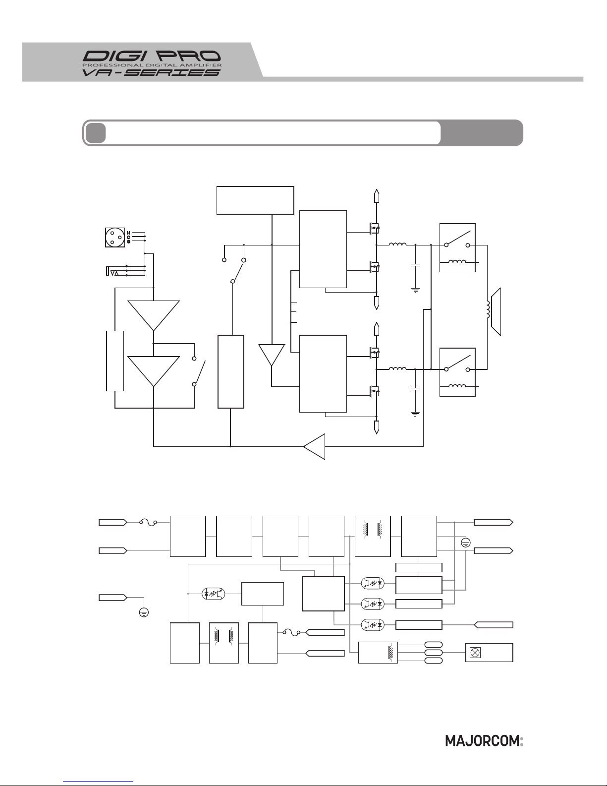
BlockDiagram(1CH)
Page 23
23
6
INPUT
H
C
G
OVER CURRENT P/T
FE T
SHORT P/T
IM PEDAN CE
MA TCHIN G
AU DIO L EVEL METE R
+VBB
PWM
DRIVER
A.L.C
TEMPERATURE P/T
PWM
DRIVER
+VBB
FE T
IM PEDAN CE
SE LETOR
FE T
FE T
-V EE
B. AMP
-VEE
DIGITAL PROFESSIONAL AMP
AC/ DC SMPS
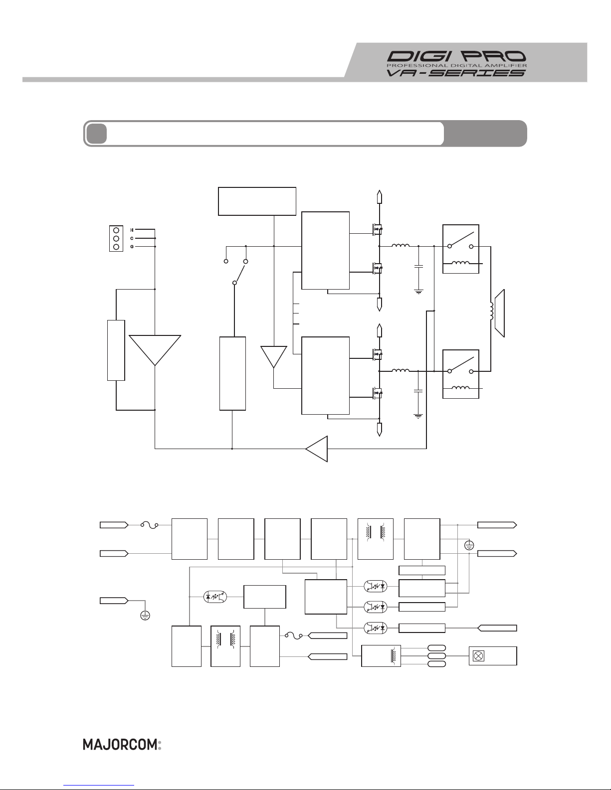
BlockDiagram(2CH/4CH)
INPUT : 200 Vac ~ 240 Vac
F/G
EMI FILTER
ACTIVE INRUSH
CURRENT
LIMITING
ISOLATED
TRANSFORM
+85VDC
-85VDC
CURRENT SENSING
RECTIFIERS
&
FILTER
PWM
MAIN SWITCHING
RECIFIERS
& P.F.C
POWER
SWITCHING
ISOLATED
TRANSFOMER
RECTIFIERS
AC/N
AC/L
REMOT CONTROL
FAN LOCK &
PROTECTION
FEED BACK CONTROL
DETECTING
CIRCUIT
O.V.P / D.T.P
REMOT CONTROL
P.F.C / PWM
CONTROL
BATTERY ( + )
MAIN
SWITCHING
BATTERY ( - )
+12 V
-12 V
FAN
AUXI Liary
FEED BACK CONTROL
O.V.P/O.C.P
&
P.W.M
Page 24
24
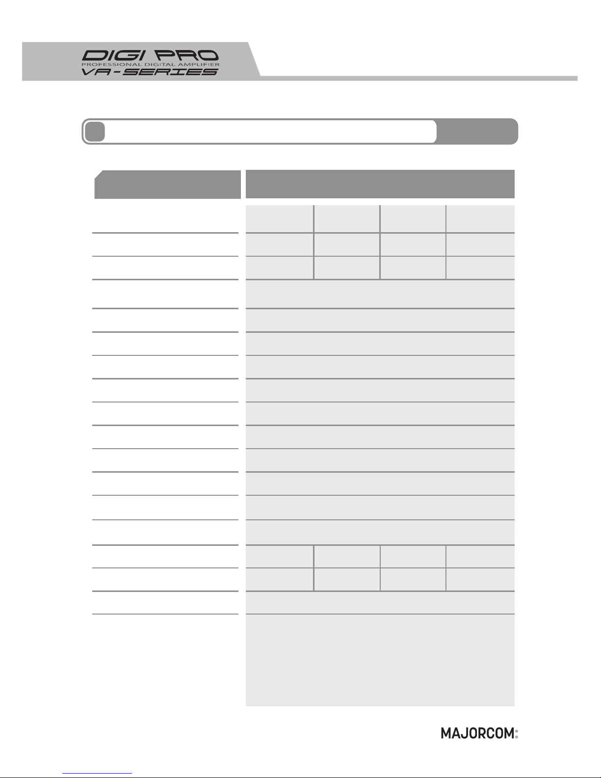
Standard
Rated Output Power (RMS)
Model
PA Output Impedance (70V/100V)
Frequency Response (-3dB/OCT)
High-pass Input Filter
(HPF,-3dB/OCT)
Dynamic Range
S/N Ratio (S/N)
Weight
Dimensions (W x H x D)
Protection Circuit
T.H.D (RMS)
Input Level
Efficiency
Power supply / Frequency
Emergency Power supply
Permissible Temperature
Permissible Humidity
Power consumption
480 W 680 W280 W120 W
17Ω/35Ω40Ω/83Ω 8Ω/15Ω10Ω/20Ω
20 Hz ~ 20 KHz
> 100 ㏈
300 Hz
> 100 ㏈
< 1 %
483 (W) x 44 (H) x 340 (D) mm 1U (With Bracket)
Overload Protection
Thermal Protection
Speaker Short Protection
DC Output Protection
Power ON/OFF Muting
Power Short Protection
1.0 ~ 5.0 V rms
85 %
AC 200 ~ 240V / 50, 60 ㎐
DC 22 ~ 28 V
- 10 ~ 40℃
~ 95%
620 W
340 W160 W 750 W
5 ㎏5 ㎏5 ㎏
6 ㎏
Specifications
7
Performance
DIGIPRO 2800DIGIPRO 1200 DIGIPRO 4800 DIGIPRO 6800
Page 25
25
Standard
Rated Output Power (RMS)
Model
PA Output Impedance (70V/100V)
Frequency Response (-3dB/OCT)
Dynamic Range
S/N Ratio (S/N)
Weight
Dimensions (W x H x D)
Protection Circuit
T.H.D (RMS)
Input Level
Efficiency
Power supply / Frequency
Emergency Power supply
Permissible Temperature
Permissible Humidity
Power consumption
2 X 250W 4 X 120W2 X 500W 4 X 240W
20Ω / 40Ω 41Ω / 83Ω10Ω / 20Ω 20Ω / 41Ω
20 Hz ~ 20 KHz
> 100 ㏈
> 100 ㏈
< 1 %
483(W) x 44(H) x 340(D)mm
1U (With Bracket)
483(W) x 88(H) x 340(D)mm
2U (With Bracket)
Overload Protection
Thermal Protection
Speaker Short Protection
DC Output Protection
Power ON/OFF Muting
Power Short Protection
1.0 ~ 5.0 V rms
85 %
AC 200 ~ 240V / 50, 60 ㎐
DC 22 ~ 28 V
- 10 ~ 40℃
~ 95%
1250 W 1200 W
625 W 650 W
8 ㎏ 10 ㎏7 ㎏ 9 ㎏
Specifications
7
Performance
DIGIPRO 2250 DIGIPRO 4120DIGIPRO 2500 DIGIPRO 4240
Page 26

26
MEMO
Page 27

Page 28

56 Chemin de la Flambè re 1300 TOULOUSE France
Phone : +33 (0) 5 61 31 86 87
Fax : +33 (0) 5 61 31 87 73
www.majorcom.fr
 Loading...