

Major MJ71-190, MJ71-240, MJ70-240FM, MJ71-340, MJ71-400 User Manual
...
Operators Manual & Parts List
SWIFT ROLLERMOWERS
MJ71-190
MJ71-240, MJ70-240FM
MJ71-540
MJ71-400
MJ71-340

B
Head Ofce
Major Equipment Intl. Ltd.
Ballyhaunis,
Co. Mayo,
Ireland.
Tel.: +353 (0) 9496 30572
Fax: +353 (0) 9496 30788
Email: info@major-equipment.com
UK Ofce
Major Equipment Ltd.
Major Industrial Estate,
Middleton Rd.,
Heysham,
Lancs.
LA3 3JJ
Tel.: +44 (0) 1524 850 501
Fax: +44 (0) 1524 850 502
Email: ukinfo@major-equipment.com
NETHERLANDS & GERMANY OFFICE
Major Equipment Intl. Ltd.
Postbus 29,
NL-7700 AA ,
Dedemsvaart,
Nederland.
Tel: +31 (0) 6389 19585
Email: euinfo@major-equipment.com
Web: www.major-equipment.com
Find us on FACEBOOK
MAJOR MACHINERY
View our channel
MAJOREQUIPMENT
Disclaimer
While every effort has been made in the production of this manual to ensure that the information
contained herein is full and correct, Major assumes no responsibility for errors or omissions.
Major reserves the right to modify the machinery and the technical data contained within the
manual without prior notice.
Further to this, Major assumes no liability for any damages which may result from the use of the
information contained within this manual.

Contents
Introducon
Thank you 1
Using Your Operator’s Manual 1
Safety Aspects 1
Intended use 1
Product Idencaon
Machine Serial Numbers 1
Register Your Product and Warranty Online 1
Product Specicaons 1
Safety
Machine Safety Labels 2
Hazards associated with operang Grass Cung Machinery 3
Operang Safely 4
Workstaon 4
Regulaons for use of the transmission 4
PTO Sha Safety 5
Driving Safely on Public Roads 5
Operang the Machine
Key to Main Parts 6
Inspecons before Use 7
Starng Regulaons 8
Aaching the machine to the Tractor 8
Operang the Machine/Mowing 9
Roller and Castor wheels adjustment 10
Maintenance
PTO Sha Maintenance 11
Blade Rotaon 12
Wing shas alignment 12
Greasing Schedule 12
Troubleshoong 13
MJ71 Spare Parts - Single Deck models - MJ71-190, MJ71-240
MJ71-190 16
MJ71-240 20
MJ71-240FM 24
MJ71 Wheel assembly 25
MJ71 Spare Parts - Winged Models - MJ71-540/400/340
MJ71-540 - Overview 26
MJ71-400 - Overview 26
MJ71-340 - Overview 26
MJ71-340/400/540 Body 27
MJ71-340/400/540 Body- Parts List 30
MJ71-540 Wing 31
MJ71-540 Wing - Parts list 33
MJ71-400/340 Wing 34
MJ71-400/340 Wing - Parts List 36
MJ71-340 Wing 37
MJ71-340 Wing - Parts List 39
MJ71 Blades 40
Roller End - Parts List 41
MJ71 Scraper Bars 42
LF205H-205 872-1.92 43
LF205TH-205.874-1.92 44

EEC certicate of conformity for machines
(conforming to Directive 98/37/EEC)
Company: Major Equipment Ltd.
Address: Coolnaha,
Ballyhaunis,
Co. Mayo,
Ireland.
Tel. +353949630572
Fax +353949630788
declares in sole responsibility that the product:
SWIFT ROLLERMOWER MJ71
When properly installed, maintained and used only for it’s intended purpose, complies with
all the essential Health & Safety requirements of:
• THE SUPPLY OF MACHINERY (SAFETY) REGULATIONS 2008.
• S.I. No. 299 of 2007, Safety, Health and Welfare at Work (General Application)
Regulations 2007 (Ireland).
• Health & Safety at Work, etc. Act 1974 (c.37) (UK).
• EN ISO 14121-1: 2007 ‘Safety of machinery. Principles for risk assessment’.
• EN 745 - Agricultural Machinery - Rotary Mowers and Flail Mowers - Safety.
• EN ISO 13857 - Safety of machinery: Safety distances to prevent hazard zones
being reached by upper and lower limbs.
I certify on behalf of Major Equipment Int. Ltd., that this machine when properly installed
and operated correctly, complies with all the essential Health & Safety requirements of
all legislation referred to above.
Signature : ______________ Date 12/06/2013
Managing Director

www.major-equipment.com
1
260718
Introduction
Thank you
We appreciate having you as a customer and wish you many years of safe and satised use of your machine.
Using Your Operator’s Manual
This manual is an important part of your machine and should remain with the machine when you buy it. Reading your
operator’s manual will help you and others avoid personal injury or damage to the machine. Information given in this
manual will provide the operator with the safest and most effective use of the machine.
Sections in your operator’s manual are placed in a specic order to help you understand all the safety messages so you
can operate this machine safely. You can also use this manual to answer any specic operating or servicing questions.
Safety Aspects
Your manual contains special messages to bring attention to potential safety concerns, machine damage as well as
helpful operating and servicing information. Please read all the information carefully to avoid injury and machine damage.
Intended use
This machine is a grass cutting machine and designed for cutting grass. Moreover, it must only be used with a suitable
tractor (see “Product Specications” section of this booklet) and driven by an adequate drive-line of the tractor PTO. All
other use is strictly prohibited.
Product Identication
Machine Serial Numbers
If you need to contact MAJOR or your MAJOR dealer for information on servicing or spare parts, always provide the
product model and serial numbers. Model and Serial number can be found on the Serial Plate located on the machine.
We suggest that you record your machine details below:
Model No: ______________________________
Serial No: ______________________________
Date of Purchase: ______________________________
Dealer Name: ______________________________
Dealer Telephone: ______________________________
Register Your Product and Warranty Online
To register your product through the Internet, simply go to the Support section on www.major-equipment.com. Completing
the information, either online or with the product warranty card, will ensure the customer that their product receives all
post sales service and important product information.
This machine is warranted for 12 months with. No warranty is given where the machine is being used as a hire machine.
Warranty is against faulty workmanship or parts.
Warranty covers parts only. All parts must be returned to the manufacturer. No warranty can be considered unless parts
are returned. All replacement parts will be supplied on a chargeable basis until warranty has been accepted.

www.major-equipment.com
2
Product Specications
Model Overall
Width
Working
Width
Transport
Width
Power
(HP)
PTO rpm Cutting
Height
(mm)
Rotors/
Blades
Weight
(kg)
Blade
tip
speed
(m/s)
Mowing
Rates
(Acres/hr
at 7mph)
MJ71-190 2.0m (6' 6") 1.9m (6' 3") 2.00m (6' 6") 25-70 540 10-150 3/6 465 75 5.3
MJ71-240 2.5m (8' 2") 2.40m (8') 2.50m (8' 2") 30-80 540 10-150 4/8 570 75 6.7
MJ71-340 3.48m 3.40m 1.90m 40-90 540 10-150 5/10 940 75 9.5
MJ71-400 4.16m 4.00m 1.90m 50-100 540 10-150 6/12 1100 75 11.4
MJ71-540 5.54m 5.40m 1.90m 50-100 540 10-150 8/16 1270 75 15.1
To avoid injury, read the manual
Check the tightness of the transmission
Rotating blade hazard
PTO entanglement
hazard - keep clear
of PTO drives.
Safety
Machine Safety Labels
The machine safety labels shown in this section are placed in important areas on your machine to draw attention to
potential safety hazards.
On your machine safety labels, the words DANGER, WARNING, and CAUTION are used with this safety alert symbol.
DANGER identies the most serious hazards.
The operator’s manual also explains any potential safety hazards whenever necessary in special safety messages that
are identied with the word, CAUTION, and the safety-alert symbol .
Grease points
Shaft alignment
High oil pressure
hazard
Moving parts
Maximum speed
Maximum PTO input

www.major-equipment.com
3
Hazards associated with operating Grass Cutting Machinery
Shear Hazard
Shear hazards are created when the edges of two objects move toward or next to each other closely enough to cut
relatively soft material. This can include the parts of the machine under hydraulic control when operating from transport
to mowing position. Note, the wing units are designed to oat independently of the centre deck & are free to move within
operating limits.
Crush Hazard
Bystanders can be injured when machine is lowered into mowing position. Winged machines have crush points around
the hinge areas & between the wing & main body. Always use transport locking bars when not in use (winged models
only).
Rotating Blade Hazard
All persons are at risk if they place their hands or feet under the machine when it is raised from the ground when the
blades are in motion.
Pinch Hazard
Pinch points are created when two objects move together, with at least one of them moving in a circle. This hazard is
common in power transmission devices such as Belt Drives, Gear Drives & Rollers. Ensure all guarding is present.
Wrap Hazard
Any exposed, rotating machine component is a potential wrap point. Injuries usually occur when loose clothing or long
hair catch on and wrap around rotating parts such as PTO shafts or Drive shafts on the machine. Ensure all guarding
is present.
Free-wheeling parts Hazard
The heavier a revolving part is, the longer it will continue to rotate after power is shut off. This characteristic is called
‘free-wheeling.’ Blades, and various other components, drive shafts etc., will continue to move after power is shut off often for several minutes. Injuries occur when:
• Operators shut off equipment, and attempt to clean or adjust a machine before components have completely stopped
moving.
• Shear bolt protection device in PTO shaft shears & the mowing parts are still spinning but the primary PTO shaft is
stationary. Operator awareness is the key to safety around freewheeling parts. Never raise the machine while the
blades are still rotating.
Thrown objects Hazard
Machines throw material as a natural part of doing their job. Foreign objects, such as stones, sticks and other debris,
may be taken into this equipment and expelled at tremendous speed. These objects are contained by the sides of the
machine and by the rear/front rollers / guards / chain guards / rubber skirts depending on model of your machine.
Ensure bystanders are clear from the machine & cannot be hit with debris expelled from the machine. Bystanders or
animals in the path of thrown objects could be seriously injured. Never operate machine with decks raised from the
ground as this makes the front/rear protection redundant.
Hydraulic Hazard (if applicable)
Hydraulic systems store considerable energy. Careless servicing, adjustment, or replacement of parts can result in
serious injury. High pressure blasts of hydraulic oil can injure eyes or other body parts. The following precautions are
crucial:
• Make certain the hydraulic pump is turned off.
• Lower attached equipment to the ground.
• Conrm that load pressure is off the system.
A pinhole leak in an hydraulic hose is a serious hazard. A leak may not be visible, and the only sign may be a few drops
of uid. Never inspect hydraulic hoses with your hands, because a ne jet of hydraulic uid can pierce the skin.
Slips, Trips and Falls Hazard
Slips and falls often result from:
1. Slippery footing on the ground
2. Cluttered steps and work platforms.
The potential for slips and falls can be greatly reduced by using good judgement and practicing good housekeeping on
and around equipment.

www.major-equipment.com
4
Operating Safely
This MAJOR machine is designed to operate at a PTO rate which is stated in the Product Specications part of this
booklet. Ensure tractor PTO output is set at a correct RPM rate. This MAJOR machine must only be used for purposes
outlined in the Intended Use section of this booklet. All other use is strictly prohibited.
Users should become thoroughly familiar with the contents of this manual before using, servicing and
mounting the implement to the tractor and all other pertinent operations. Never wear jewellery, loose clothing
such as ties, scarves, belts, unbuttoned jackets or dungarees with open zips which could become caught up
in moving parts.
Always wear approved garments complying with accident prevention provisions such as non-slip shoes, ear
muffs, goggles and gauntlets. Wear a jacket with reecting stickers if the implement is used near public
highways.
Consult your retailer, the Labour Health Service or your nearest equivalent authority for the information about
the current safety provisions and specic regulations with in order to ensure personal safety.
ALWAYS DISENGAGE PTO, SWITCH OFF THE TRACTOR ENGINE AND ENGAGE THE PARKING BRAKE
BEFORE MAKING ADJUSTMENT TO THE MACHINE.
NEVER PLACE LIMBS UNDER THE MACHINE WHILE ROTOR(S) ARE TURNING. ROTOR(S) CAN
REMAIN TURNING FOR UP TO 1 MINUTE AFTER DISENGAGING PTO.
Workstation
The operator must remain seated while working the machine. If the machine is a winged unit and the wings need to
be raised/lowered the operator must not leave the tractor. Always ensure the PTO has been turned off and the parking
brake applied before leaving the tractor cab or carrying out maintenance.
NEVER OPERATE THE HYDRAULICS WITH THE TRACTOR SWITCHED OFF
Regulations for use of the transmission
The transmission to the gearboxes is protected throughout the machine by both PTO shafts and bolt down covers. All
guarding should be kept efcient and in good condition. If the condition is poor, the guarding should be renewed before
the implement is used.
UNLESS IT IS CORRECTLY PROTECTED THE TRANSMISSION COULD CAUSE DEATH SINCE IT CAN
CATCH ON PARTS OF THE BODY OR CLOTHING
Ensure retaining chains are correctly anchored on all PTO shafts, preventing them from turning. Ensure drive line can
turn easily within the shield. Keep spline grooves clean and greased so that PTO shaft can connect easily. Besides
being described in this booklet, the method by which the PTO shaft is connected to the tractor must be checked out with
the instructions in the tractor manufacturer’s manual.
Noise Hazard
Please note that the machine is normally used outdoors and that the position of the operator is seated in the driving seat
of the tractor. It is advisable to consult the prescriptions listed in tractor operator and maintenance manuals.
The acoustic pressure at a distance of 2.6m from the centre of the machine and at a height of 2.0m, with the implement
operating in a no load condition can reach 90 dBA. In a loaded condition & a PTO rate of 540 rpm the value can reach
97dBA. Higher rate of PTO input will result in in higher noise levels. Always wear hearing protection.
www.major-equipment.com
5
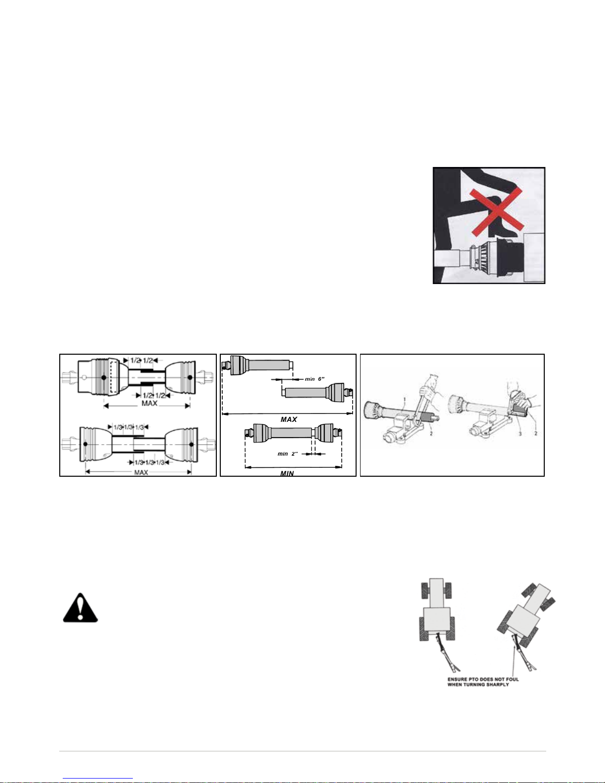
PTO Shaft Safety
Maximum PTO input is specied in the Product Specications section of this booklet. Contact your nearest dealer or
a specialised retail outlet if the PTO must be replaced with a longer one, since this must belong to the same power
category and possess the same characteristics. An unsuitable PTO could easily break.
The tractor PTO shaft length may be altered to suit the individual tractor model. When the machine is in operation, the
PTO shaft should have a minimum 1/3 engagement as shown in the diagrams. After the machine has been hitched to
the tractor, it should be checked in various positions that the drive line is the correct length. If the PTO is too short and
tends to slip out of place, it must be replaced with a longer one.
Driving Safely on Public Roads
Check the local Highway Code regulations before driving the tractor on public highways with an implement attached.
Check the reectors, hazard ashers and/or projecting load indicators are installed when required and efcient. These
indicators must be installed correctly and easily seen by the drivers of other vehicles.
Bystanders must not be allowed to lean against or climb onto the machine during transport or while working. Do not
allow bystanders to ride on the machine.
MAXIMUM TRANSPORT SPEED MUST NOT EXCEED 30 km/r (18 MPH)
TRAILED MODELS MAXIMUM SPEED IS 25 km/h
If the PTO shaft is too long, it should be shortened in the following way:
• Set the machine at a minimum distance from the tractor, then brake the
tractor and switch off the engine.
• Separate the two halves of the PTO. Insert the female part into the tractor
PTO and the male part into the machine PTO, checking that the position
is correct by means of the xing pins.
• Line up the two halves of the PTO together, keeping them parallel.
• Using a felt tip pen, match mark the place where the two halves must be
shortened as shown.
• First cut shield “1” and use part “2” as a reference to cut the splined shaft.
• Proceed in the same way for the second half.
• Trim and chamfer the two cut ends of the PTO and clean off all swarf
and shavings.
• Grease the two proles and join the two halves of the PTO together.
• Mount the PTO shaft and check that its length is correct as before.
Do not use the shaft cone
as a step
General safety instructions
Precautions to be taken while working with the machine:
1. Do not operate the machine when you are tired;
2. Before starting mowing, make sure that the area is clear of people or animals.
3. Before starting adjusting the machine, it is mandatory to disconnect the PTO, to turn off the engine of the tractor, apply
handbrake and wait for the turning parts to become still and placed on the ground.
4. It is mandatory to read all the safety requirements and the operator’s manual of the machine.
5. If you are not sure how to use the machine, please contact the manufacturer or the dealer.
www.major-equipment.com
6
1
6
260718
2
3 4
5
7
8
6
8
10
11
12
13
13
9
4
13
12
14
2
8
8
7
2
14
15
16
17
9
Operating the Machine
This machine is designed to be connected to a tractor by using a standard 3 point linkage connection. It can be installed
either to the front or to the rear of the tractor, depending on the model of your machine.
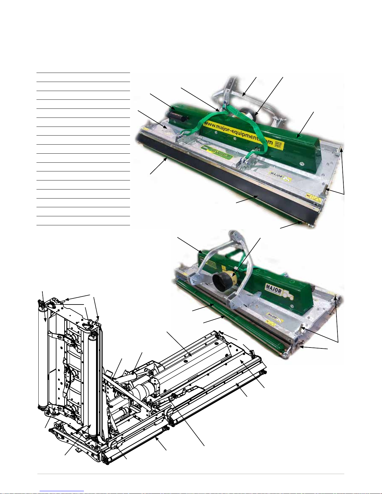
Key to Main Parts
1 Body
2 Drivetrain cover
3 A-Frame
4 Gearbox PTO cover
5 PTO shaft
6 Rear roller
7 Strap
8 Roller height adjuster rod
9 Roller height indicator
10 Top Link
11 Blade
12 Front roller
13 Scraper bar
14 Rubber deector
15 Lighting kit
16 Hydraulic Ram
17 Wing
Rear mounted machine shown
Rear mounted machine shown
www.major-equipment.com
7
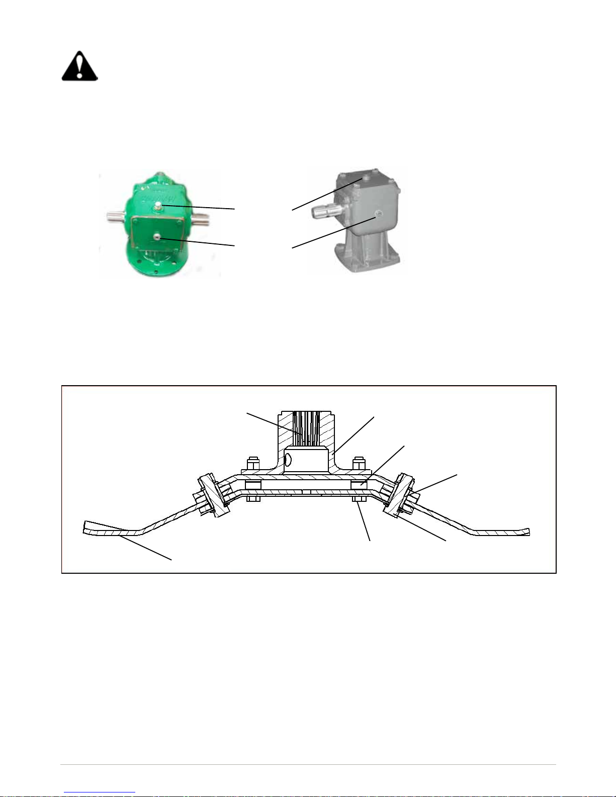
GB.03499
Primary gearbox
Inspections before Use
Always disengage PTO, Switch off tractor engine and engage the parking brake before making adjustments
to the machine.
1. With the whole machine as level as possible, check the oil level in the Primary and Rotor Gearboxes and top up as
required with recommended gear oil through the oil ller plug indicated. The correct level is at the oil level plug
indicated.
Oil ller
plug
Oil level
plug
2. Grease the PTO shaft universal joints, drive shaft bearing and carrying arm pivots.
3. Check the blades for wear and damage and replace worn blades with new ones if requried.
4. If the blade assembly is removed check the blade mounting ensure the gearbox shaft nut is tight and retained in place
by split pin.
Rotor gearbox
5. Check tightness of all nuts, bolts and retaining screws after the rst and second hours of work.
6. Ensure safety guards and aps are in place at all times where tted. If these become worn or missing, replace them
immediately with new ones.
7. Due to the corrosive nature of grass when cut, wash down the machine when nished mowing, especially when the
machine is being stored for a long period of time.
Blade mounting
bolts
Spacer
bushings
Cranked
blade
Blade pivot
bush
Gearbox
output shaft
Blade pivot
bolt
Blade Mount

www.major-equipment.com
8
Transport Position
Before raising the machine wait until the transmission and the blades are completely still.
During the transport of the machine it is recommended that the PTO shaft is disconnected.
1. Check machine is hitched to the tractor as described. Ensure the tractor parking brake is applied
2. Ensure moving parts become still then transform the machine into transport position by hydraulic control
3. During the transport and any time the machine shall be raised, the raising device shall be adjusted to assure that the
machine is at least 250mm over the ground.
Attaching the machine to the Tractor
Always operate on level ground when attaching/detaching the machine. This will prevent dangerous movement.
Never allow anyone to stand between the tractor and the machine.
Three Point Linkage Models
1. Adjust both lift arms of the tractor until they are level in relation to each other.
2. Hitch the lower linkage arms to the Machine and connect the top link and PTO shaft. Ensure that the locking pins are
secure.
3. With the Machine lowered in its operating position, adjust the top link until the strap is slack, allowing the Machine to
produce a uniform nish in varying ground conditions.
4. Connect the PTO shaft. Check for the length
Trailed Models
1. Adjust the tractor hitch pin so that the hitch pin is approximately 400 mm (16”) from the end of the tractor PTO shaft.
2. Adjust the machine hitch eye to suit the tractor drawbar height paying particular attention to keep both height adjusting
bolts as far as possible on the adjusting bracket. Careful adjustment of the hitch eye height at this stage is
necessary in order to allow the machine to function safely and correctly.
3. Connect the machine to the tractor. Ensure no one is standing between the tractor and the Machine.
4. Before connecting the PTO shaft to the tractor, check it for length as shown earlier.
Starting Regulations
Always check that any imminently dangerous conditions have been eliminated before using the machine.
Ensure all guarding is present & the operator is fully aware of the operations of the machine.
Always ensure the pins lock the PTO shaft yoke ends onto the spline shafts on both the tractor and the
implement. An unlocked shaft could slip out of position, causing notable mechanical damage and serious
injury to both operator and bystanders.
Transport Speed
Transport Speed of Trailed models should not exceed 25 km/h
www.major-equipment.com
9
Operating the Machine/Mowing
Never place limbs under the machine while rotors are turning. Rotors can remain turning for up to 1 minute
after disengaging PTO.
While operating this machine the PTO input rate should not exceed the RPM stated in the Product
Specications section of this booklet. Always operate on level ground when connecting/disconnecting the
implement. This will prevent dangerous movement.
Never allow anyone to stand between the tractor and the machine. Ensure the machine is attached correctly
to the tractor as previously described. Always start up the tractor PTO at a low RPM. Build up to operating
speed, select a suitable forward gear & proceed to cut grass.
1. Hitch the machine as outlined in the previous section. Ensure bystanders are clear from the machine & cannot be
hit with debris expelled from the machine.
2. Locate the Parking Jack on its side under the PTO shaft on the stub provided (Trailed models only)
3. Ensure the PTO stand is ipped down. (Trailed models only)
4. Check PTO shaft is fully engaged on tractor PTO splines.
5. Raise the machine by hydraulic control. (Trailed models only)
6. Flip back axle and drawbar ram stoppers. (Trailed models only)
7. Lower the machine by hydraulic control to the ground or use tractor linkage controls.
8. After clearing the vicinity of bystanders, relocate the Wing Transport Locking Bars. Lower the wings by hydraulic
control. Ensure hydraulic ram is fully closed. (Winged mowers only).
9. Start up the tractor PTO at a low RPM.
10. Build up to operating speed, select a suitable forward gear & proceed to cut grass.
Mowing Position
Transport Position
Transport Position (Winged models only)
ALWAYS HAVE THE TRACTOR SWITCHED ON WHEN RAISING THE WINGS INTO TRANSPORT POSITION.
IMPORTANT: The transport locking bars, transport pin and axle ram stopper should always be slotted into place while
transporting the machine. Doing this removes pressure from the hydraulic system. Failure to use the safety equipment
can cause mechanical as well as physical damage.
Top Link Position Axle Locks
Drawbar Locks
Transport Position Transport Position
Mowing Position Mowing Position

www.major-equipment.com
10
1
3
B
C
D
A
A
B
C
C
D
4
5
5
2
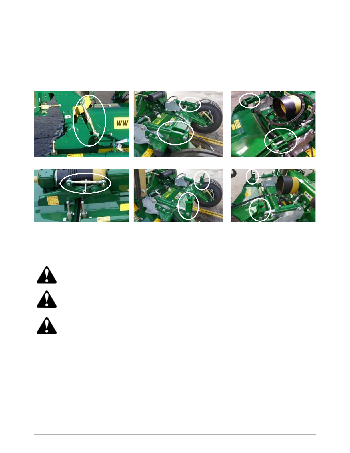
Castor wheels (optional)
To adjust the height of front wheels lift up the
machine and:
1. Unscrew and remove Bolt A;
2. Slide down the Castor Yoke B and remove
it;
3. Depending on the desired cutting height
place Spacers C above or below Castor
Arm D.
4. When adjustment is complete, relocate
Castor Yoke B and secure it with Bolt A.
5. Repeat this procedure for the other wheel.
Roller
To adjust the height of the roller follow this procedure at
both sides of the roller:
1. Loosen Bolts B and C (Note: You do not have to remove
these bolts, half of the turn will sufce to allow movement);
2. Turn Nut D clockwise to increase the cut height or anticlockwise to decrease the cut height;
3. Match the height of the roller on both sides of the machine
by checking the position of Arrow A;
4. When adjustment is complete, re-tighten Bolts B and C.
Scraper bar
In order for a scraper bar to function properly, it
should be kept tensioned. To tension the scraper
bar (1) tighten up nuts (2) at both ends of the roller
(3). Locate the scraper bar bracket (4) in a desired
position by loosening/tightening bracket nut (5).
Roller and Castor wheels adjustment
In order to achieve desired cutting height, castor wheels and roller should be adjusted.

www.major-equipment.com
11
Maintenance of other components
• All nuts and bolts in the transmission including Rubber couplings, Star Drives, PTO Shafts and Gearboxes should
be checked for tightenes after mowing at the following intervals:
1st 40 hours
1st 100 hours
1st 250 hours
And every 250 hours thereafter.
• Check blades on a regular basis for wear. Replace any damaged or worn parts immediately.
Maintenance
The machine must always be disconnected form the tractor before any cleaning, lubricating and servicing operations
can be carried out. Maintenance must be carried out by qualied personnel.
If emergency operations are required whilst the machine is connected to the tractor, switch off the engine, engage the
parking brake and disengage the PTO.
Good, regular maintenance and correct use are advised if the machine is to remain safe and long lasting.
PTO Shaft Maintenance
Guard Removal and Yoke End Greasing
1. Prise back locking tabs
2. Pull back PTO Guard
3. Grease points as shown
4. Push Guard into position
5. Click into place
6. Tie check chain
PTO Guard Greasing Intervals
 Loading...