

Page 1

MAJOR
FLAIL CATCHER
MJ2000
Operator Manual
& Parts List
Page 2

Head Ofce
Major Equipment Intl. Ltd.
Ballyhaunis,
Co. Mayo,
Ireland.
UK Ofce
Major Equipment Ltd.
Major Industrial Estate,
Middleton Rd.,
Heysham,
Lancs.
LA3 3JJ
NETHERLANDS & GERMANY OFFICE
Major Equipment Intl. Ltd.
Postbus 29,
NL-7700 AA ,
Dedemsvaart,
Nederland.
Web: www.major-equipment.com
Find us on FACEBOOK
MAJOR MACHINERY
View our channel
MAJOREQUIPMENT
Disclaimer
While every effort has been made in the production of this manual to ensure that the information
contained herein is full and correct, Major assumes no responsibility for errors or omissions.
Major reserves the right to modify the machinery and the technical data contained within the
manual without prior notice.
Further to this, Major assumes no liability for any damages which may result from the use of the
information contained within this manual.
Page 3

Contents
Introduction
Thank you 1
Using Your Operator’s Manual 1
Safety Issues 1
Product Identication
Machine Serial Numbers 1
Product Specications 1
Register Your Product and Warranty Online 1
Safety
Machine Safety Labels 2
Operating Safely 2
Workstation 3
Regulations for use of the transmission 4
PTO Shaft Safety 4
Driving Safely on Public Roads 4
Operating the Machine
Inspections before Use 5
Key to Main Parts 5
Starting Regulations 5
Hitching to the Tractor 6
Operating the Machine 6
Catcher Locking Bar Positions 6
Emptying the Catcher 7
Adjusting the Cutting Height 8
Removing the machine from the tractor 8
Maintenance
PTO Shaft Maintenance 8
Maintenance Schedule 9
Changing the gearbox oil 9
Belt Tension Adjustment 10
Checking and Replacing Blades 10
Storing the machine for long periods of time 11
Disposing of the Machine 11
Trouble Shooting 11
Spare Parts
Chute Assembly 13
Bogey Assembly 14
Flail Assembly 16
Rotor Assembly 17
Catcher Assembly 18
Scarier Assembly 19
Hydraulics 20
Page 4

EEC certicate of conformity for machines
(conforming to Directive 98/37/EEC)
Company: Major Equipment Ltd.
Address: Coolnaha,
Ballyhaunis,
Co. Mayo,
Ireland.
Tel. +353949630572
Fax +353949630788
declares in sole responsibility that the product:
MJ2000 FLAIL COLLECTOR
When properly installed, maintained and used only for it’s intended purpose, complies with
all the essential Health & Safety requirements of:
• THE SUPPLY OF MACHINERY (SAFETY) REGULATIONS 2008.
• S.I. No. 299 of 2007, Safety, Health and Welfare at Work (General Application)
Regulations 2007 (Ireland).
• Health & Safety at Work, etc. Act 1974 (c.37) (UK).
• EN ISO 14121-1: 2007 ‘Safety of machinery. Principles for risk assessment.
• EN 745 - Agricultural Machinery - Rotary Mowers and Flail Mowers - Safety.
• EN ISO 13857 - Safety of machinery: Safety distances to prevent hazard zones being
reached by upper and lower limbs.
• EN ISO 13857:2008, EN ISO 4413:2010; EN ISO 4254-1:2015
• ISO 11684:2010; ISO 4254-13:2012
I certify on behalf of Major Equipment Int. Ltd., that this machine when properly installed
and operated correctly, complies with all the essential Health & Safety requirements of
all legislation referred to above.
Signature : ______________ Date 11/05/2017
Managing Director
Page 5

1
www.major-equipment.com
Introduction
Thank you
We appreciate having you as a customer and wish you many years of safe and satised use of your machine.
Using Your Operator’s Manual
This manual is an important part of your machine and should remain with the machine when you buy it.
Reading your operator’s manual will help you and others avoid personal injury or damage to the machine. Information
given in this manual will provide the operator with the safest and most effective use of the machine.
Sections in your operator’s manual are placed in a specic order to help you understand all the safety messages so
you can operate this machine safely. You can also use this manual to answer any specic operating or servicing ques-
tions.
Safety Issues
Your manual contains special messages to bring attention to potential safety concerns, machine damage as well as
helpful operating and servicing information. Please read all the information carefully to avoid injury and machine damage.
Product Identication
Machine Serial Numbers
If you need to contact MAJOR or your MAJOR dealer for information on servicing or spare parts, always provide the
product model and serial numbers.
We suggest that you record your machine details below:
Model No: ____________________________________
Serial No: ____________________________________
Date of Purchase: ____________________________________
Dealer Name: ____________________________________
Dealer Telephone: ____________________________________
Product Specications
Model MJ2000
Overall Width 2.2m
Working Width 2m
Transport Width 2.3m
Power (HP) 50-75
PTO rpm 540
Blade Speed 2006m/min
Cutting Height 12 - 150mm
Weight 1400kg
Collector Capacity 3m³
Register Your Product and Warranty Online
To register your product through the Internet, simply go to the Support section on www.major-equipment.com.
Completing the information, either online or with the product warranty card, will ensure the customer that their product
receives all post sales service and important product information. The MAJOR MJ2000 is warranted for 12 months.
Page 6

2
www.major-equipment.com
No warranty is given where the machine is being used as a hire machine. Warranty is against faulty workmanship or
parts with the exception of blades, belts and any other consumable parts.
Safety
Machine Safety Labels
The machine safety labels shown in this section are placed in important areas on your machine to draw attention to
potential safety hazards.
On your machine safety labels, the words DANGER, WARNING, and CAUTION are used with
this safety-alert symbol. DANGER identies the most serious hazards.
The operator’s manual also explains any potential safety hazards whenever necessary in special
safety messages that are identied with the word, CAUTION, and the safety-alert symbol.
Operating Safely
The MAJOR MJ2000 is designed to operate at 540 RPM. Ensure tractor PTO output is set at 540 RPM.
The MAJOR MJ2000 must only be used for cutting grass. Moreover, it must only be used with a suitable
tractor (see product specications) and driven by an adequate drive-line by the tractor PTO. All other use is
strictly prohibited.
To avoid injury, read the manual
Fold the PTO stand down before removing the
transport pin to avoid PTO shaft damage
Rotating blade hazard
Keep wheel nuts tight.
Check tyre pressure
High oil
pressure hazard
Speed Warning: max. towing
speed for this machine
Keep transmission bolts tight Max. PTO speed for this machine
PTO entanglement
hazard - keep clear
of PTO drives.
Page 7

3
www.major-equipment.com
Operator:
The machine’s user must be an operator with a suitable technical background to enable him to understand the contents of this manual, including the diagrams found herein.
Mechanical Maintenance Staff:
This must be a qualied technician who is capable of working on all the mechanical parts.
Users should become thoroughly familiar with the contents of this manual before using, servicing and mounting the
implement to the tractor and all other pertinent operations. Never wear jewellery, loose clothing such as ties, scarves,
belts, unbuttoned jackets or dungarees with open zips which could become caught up in moving parts.
Always wear approved garments complying with accident prevention provisions such as non-slip shoes, ear muffs,
goggles and gauntlets. Wear a jacket with reecting stickers if the implement is used near public highways.
Consult your retailer, the Labour Health Service or your nearest equivalent authority for the information about the cur-
rent safety provisions and specic regulations with in order to ensure personal safety.
ALWAYS DISENGAGE PTO, SWITCH OFF THE TRACTOR ENGINE AND ENGAGE THE PARKING
BRAKE BEFORE MAKING ADJUSTMENT TO THE MACHINE.
NEVER PLACE LIMBS UNDER THE MACHINE WHILE ROTORS ARE TURNING. ROTORS CAN REMAIN
TURNING FOR UP TO 1 MINUTE AFTER DISENGAGING PTO.
Noise:
Measurements of the noise issued by the machine indicate that the equivalent noise level is such as to maintain the
daily level to which the operators are exposed within a value of less than 70 dBA. This measurement was made with
a sound level meter set at a distance of about 1.6 m from the machine and at a height of 2 m, operated (no-load) at
a PTO rotation rate of 450 rpm on grassy land. Please also note that the machine is normally used outdoors and that
the position occupied by the operator is seated in the driving seat of the tractor. Also consult the prescriptions listed in
the tractor use and maintenance manual.
Vibrations:
During normal operation, the machine will not transmit appreciable vibrations to the tractor or, thus, to the operator.
These vibrations are less than 2.5 m/sec2. to the operator’s upper limbs and less than 0.5m/sec•’. to the seated part
of the operator’s body. Consult the tractor manual for the vibrations transmitted by the tractor itself.
Disclaimer:
The mower has been built in compliance with the accident prevention instructions in force and therefore the manufacturer cannot be held responsible for damage resulting from:
• use of the machine with faulty or missing guards
• improper use of the machine
• use of the machine by untrained or unauthorised personnel
• incorrect assembly of the mower;
• use of the mower on the wrong tractor;
• lack of maintenance
• unauthorised modications or work carried out on the machine
• use of non-original spare parts or those which are not specic to the machine
• failure to observe all or some of the instructions
• exceptional weather conditions.
Applicable laws and instructions: The machine complies with the relevant standards in force.
Residual Risks
• Risk of severing: The rotating blades may cause serious injury to limbs.
• Risk of ejection of solid objects: The rotating blades may eject solid objects capable of hitting people, animals or
anything else in the vicinity.
• Risk of entanglement: Clothes or limbs may become entangled in the rotating universal shaft causing serious damage or harm to the person involved.
Page 8
4
www.major-equipment.com
Workstation
The operator must remain seated while working the machine. When the wings need to be raised and lowered the operator must leave the tractor. Always ensure the PTO has been turned off and the parking brake applied before leaving
the tractor cab. The operator must always apply the parking brake, and turn off the engine before leaving machine or
carrying out maintenance.
NEVER OPERATE THE HYDRAULICS WITH THE TRACTOR SWITCHED OFF
Regulations for use of the transmission
The transmission to the gearboxes is protected throughout the machine by both PTO shafts and bolt down covers.
All guarding should be kept efcient and in good condition. If the condition is poor, the guarding should be renewed
before the implement is used.
UNLESS IT IS CORRECTLY PROTECTED THE TRANSMISSION COULD CAUSE DEATH SINCE IT CAN CATCH
ON PARTS OF THE BODY OR CLOTHING
Ensure retaining chains are correctly anchored on all PTO shafts, preventing them form turning. Ensure drive line can
turn easily within the shield. Keep spline grooves clean and greased so that PTO shaft can connect easily. Besides
being described in this manual, the method by which the PTO shaft is connected to the tractor must be checked out
with the instructions in the tractor manufacturer’s manual.
PTO Shaft Safety
MAX PTO INPUT 540 R.P.M. Contact your nearest dealer or a specialised retail outlet if the PTO must be replaced
with a longer one, since this must belong to the same power category and possess the same characteristics. An
unsuitable PTO could easily break.
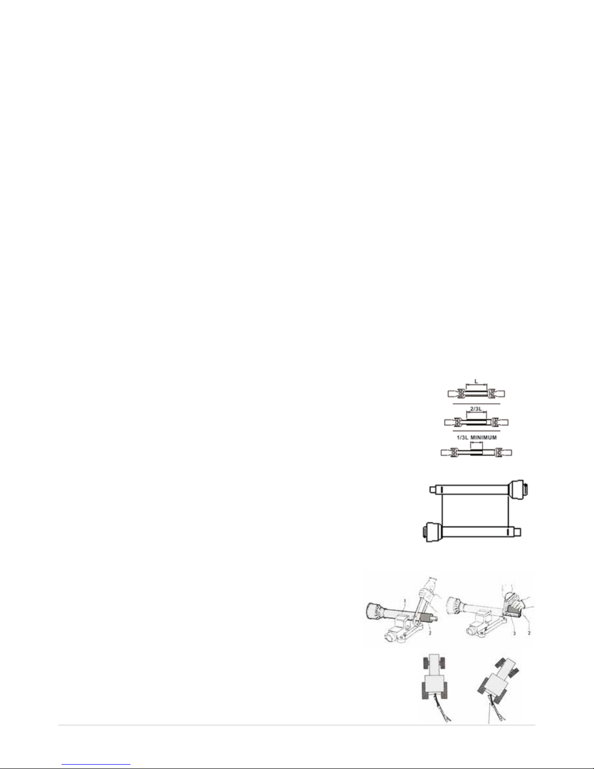
The tractor PTO shaft length may be altered to suit the individual tractor model. When
the machine is in operation, the PTO shaft should have a minimum 1/3 engagement as
shown in the diagrams. After the Rollermower has been hitched to the tractor, it should
be checked in various positions that the drive line is the correct length. If the PTO is too
short and tends to slip out of place, it must be replaced with a longer one.
If the PTO shaft is too long, it should be shortened in the following way:
• Set the machine at a minimum distance from the tractor, then brake the tractor and
switch off the engine.
• Separate the two halves of the PTO. Insert the female part into the tractor PTO and
the male part into the Rollermower PTO, checking that the position is correct by means
of the xing pins.
• Line up the two halves of the PTO together, keeping them parallel.
• Using a felt tip pen, match mark the place where the two halves must be shortened as shown.
• First cut shield “1” and use part “2” as a reference to cut the splined
shaft.
• Proceed in the same way for the second half.
• Trim and chamfer the two cut ends of the PTO and clean off all swarf
and shavings.
• Grease the two proles and join the two halves of the PTO together.
• Mount the PTO shaft and check that its length is correct as before.
The shaft must not reach the end of the tube or project from this. Ensure the PTO
does not bottom when turning
Page 9
5
www.major-equipment.com
Driving Safely on Public Roads
Check the local Highway Code regulations before driving the tractor on public highways with a towed implement.
Check the reectors, hazard ashers and/or projecting load indicators are installed when required and efcient. These
indicators must be installed correctly and easily seen by the drivers of other vehicles.
Bystanders must not be allowed to lean against or climb onto the machine during transport or while working. Do not
allow bystanders to ride on the machine.
MAXIMUM TRANSPORT SPEED MUST NOT EXCEED 30Km/Hr (22 MPH)
Operating the Machine
Inspections before Use
Always disengage PTO, Switch off tractor engine and engage the parking brake before making adjustment to the
machine.
Check the machine to ensure that the serial number and all stickers have been afxed.
Check that all points are greased.
Check the oil level in the gearbox
Check the transmission belts to ensure that their tension is correct.
Check for oil leaks.
Check to see that all safety devices are installed and efcient.
General inspection during operation
Inspect the knives to ensure that they are free from foreign bodies. Check the implement for wear and damage. Particularly check that the knives, the drive belts and wheels are in a good condition. Check that all nuts and bolts are fully
tightened, with particular reference to the knife bolts. Check that the oil and greases in the various points are at the
correct level. Despite the previous inspections, lubricant may have partially spilt during transport and need topping up.
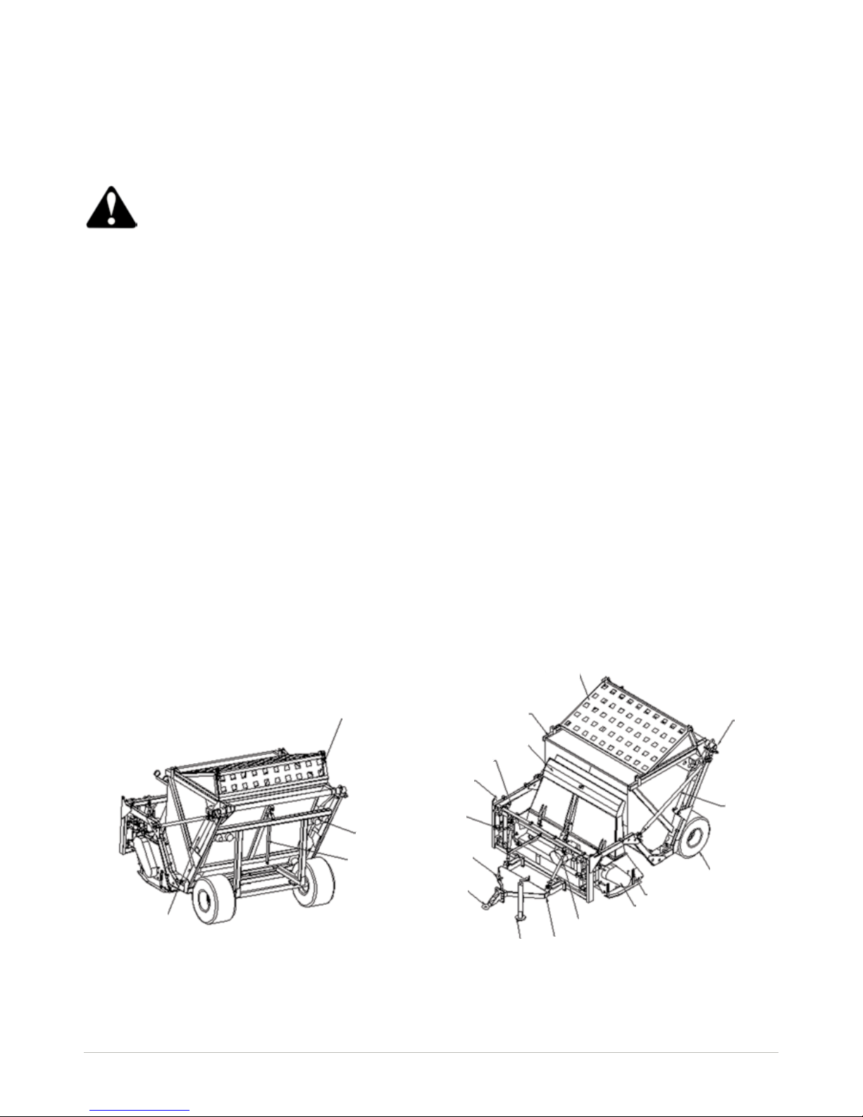
Key to Main Parts
Rear ap
Top lid
Jack
Drawbar
Belt guard
Flail mower
Axle and
wheel
Tie bar
Pivot
Gearbox
PTO guard
Bogey
Linkage
PTO stand
Swivel hitch
Chute
Transport
lock
Catcher
(hopper)
Hopper lifting
ram
Maintenance
locking bar
Rear lights,
reectors &
indicators
Page 10
6
www.major-equipment.com
Starting Regulations
Always check that any imminently dangerous conditions have been eliminated before using the machine. Ensure all
guarding is present & the operator is fully aware of the operations of the machine
Always ensure the pins lock the PTO shaft yoke ends onto the spline shafts on both the tractor and the implement. An
unlocked shaft could slip out of position, causing notable mechanical damage and serious injury to both operator and
bystanders.
Hitching to the Tractor
ALWAYS OPERATE ON LEVEL GROUND WHEN HITCHING/UNHITCHING THE IMPLEMENT. THIS WILL PREVENT DANGEROUS MOVEMENT. NEVER ALLOW ANYONE TO STAND BETWEEN THE TRACTOR AND THE
MACHINE.
• Always refer to the instruction manual supplied with the tractor.
• Reverse the tractor towards the mower, aligning the tractor lift links with the two side coupling pins.
• Turn off the tractor engine, remove the ignition key from the dashboard and insert the brake.
• After the mower has been hitched to the tractor, it should be checked in various positions that the driveline is the
correct length.
• If the PTO is too short and tends to slip out of place, it must be replaced with a longer one.
Operating the Machine
Always be careful to check that the power rating of the tractor used to tow the implement does not exceed
the maximum power rating for the model in your possession.
Check that the speed of the PTO complies with the speed required by the implement. Compare the values
on the shield of the PTO shaft.
Always become familiar with mower use before working with the implement. Make sure that you know how
to quickly stop the work operations.
1. Lower the machine until the four wheels are resting on the ground.
2. Adjust if necessary
3. Accelerate the tractor by depressing the accelerator pedal to about half its travel and then engage the PTO.
4. Advance with the tractor, setting the PTO to the required rpm rate (usually 540 or 1000 rpm).
5. The travelling speed of the tractor must be selected according to the grass to be cut, its quantity and the cutting
nish required. Optimum work speeds will be between 3 and 8 Km/hour (2/5 mph).
The cutting nish will be better if the tractor travels slowly while operating. Always raise the implement from the ground
when during manoeuvres, round bends and when reversing. Check to make sure the nish is satesfactory. Make any
adjustments as may be necessary and then continue with the job.
Never reverse with the implement unless this is strictly necessary.
In such cases, disengage the PTO and carefully check to see whether there are any
obstructions at the rear.
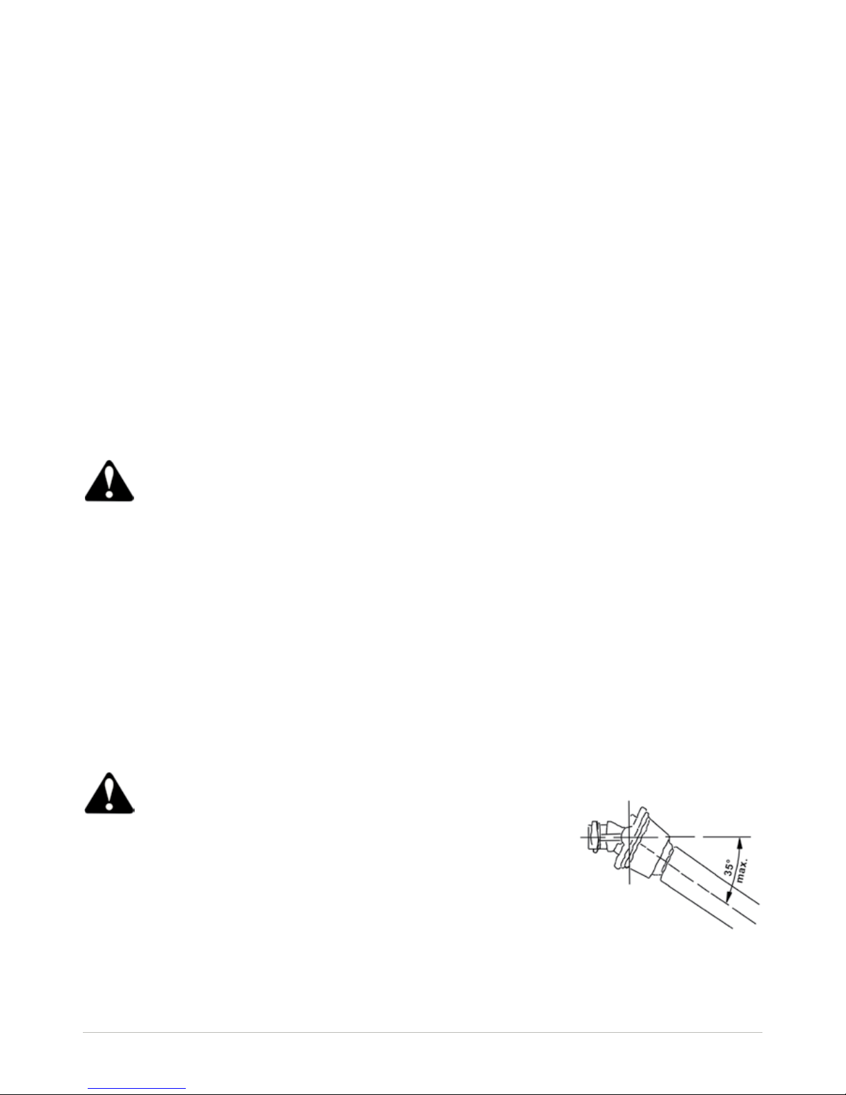
Never lift the implement more than 250 mm from the ground with the PTO engaged
or the driveline could break and risk injury to the operator. The maximum tilt the
driveline can bear with the PTO engaged is 35°
Page 11
7
www.major-equipment.com
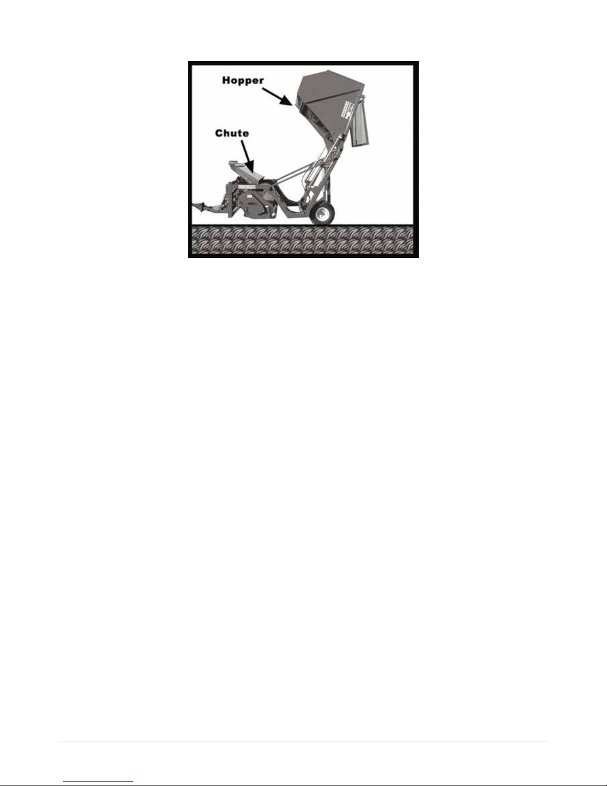
Emptying the Catcher
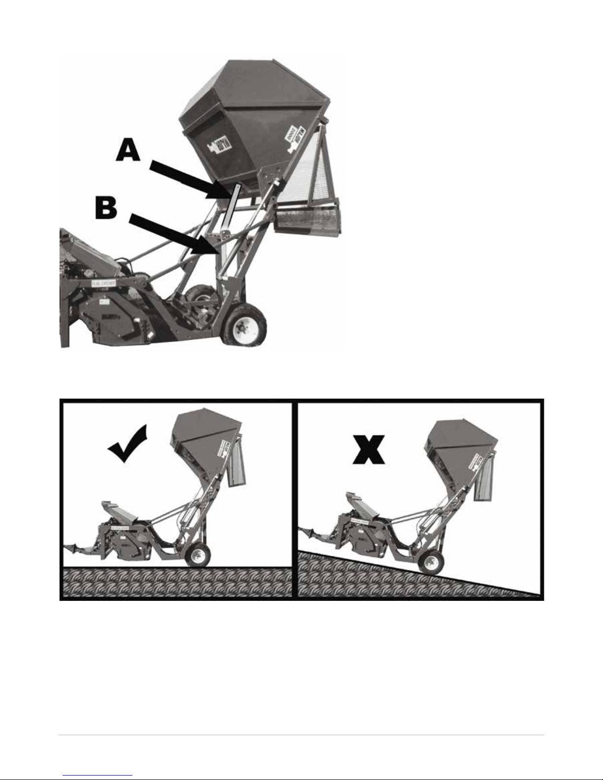
Catcher Locking Bar Positions
A Maintenance position (Retained by pin)
B Normal Operating position
1. Ensure the tractor is on level ground
2. Do not tip the grass tank (hopper) while in inclined positions, front to rear as shown above or side to side.
3. Ensure there are no bystanders around the machine.
4. Power the appropriate hydraulic spool from the tractor cab to empty the catcher
5. The chute pulls forward rst, then the grass catcher tips up over backwards emptying the contents.
NOTE: The Chute pulls forward as part of the tipping operation. Do not interfere with the hydraulic components as
they are set in the factory
6. Reverse action on the hydraulic spools will lower the catcher; continue to hold the spool in position and the chute
will fall back into operating position.
Page 12
8
www.major-equipment.com
Adjusting the Cutting Height
To alter the cutting height, adjust the side skids to the desired cutting height by:
1. Removing the four nuts on each skid
2. Relocating the skid in the desired location
3. Replace the four nuts & tighten.
Removing the machine from the tractor
1. Disengage the PTO. Set the implement on a at surface.
2. Stop the tractor and engage the parking brake.
3. Rest the mower on the ground.
4. Switch off the tractor engine.
5. Remove the ignition key from the dashboard.
6. Remove the driveline.
7. Detach the hydraulic connections.
8. Block the mower’s wheels with wedges or other suitable means
9. Remove the weight from the tractor hitch by use of the Parking Jack.
10. Detach the implement from the tractor by disconnecting the hitch
Maintenance
The machine must always be disconnected form the tractor before any cleaning, lubricating and servicing operations
can be carried out.
If emergency operations are required whilst the machine is connected to the tractor, switch off the engine, engage the
parking brake and disengage the PTO.
Good, regular maintenance and correct use are if the machine is to remain safe and long lasting.
7. Do not try to force the discharge operation in case of machine malfunction. Please get in touch immediately with
your dealer, should the tank remain jammed in high position.
Page 13
9
www.major-equipment.com
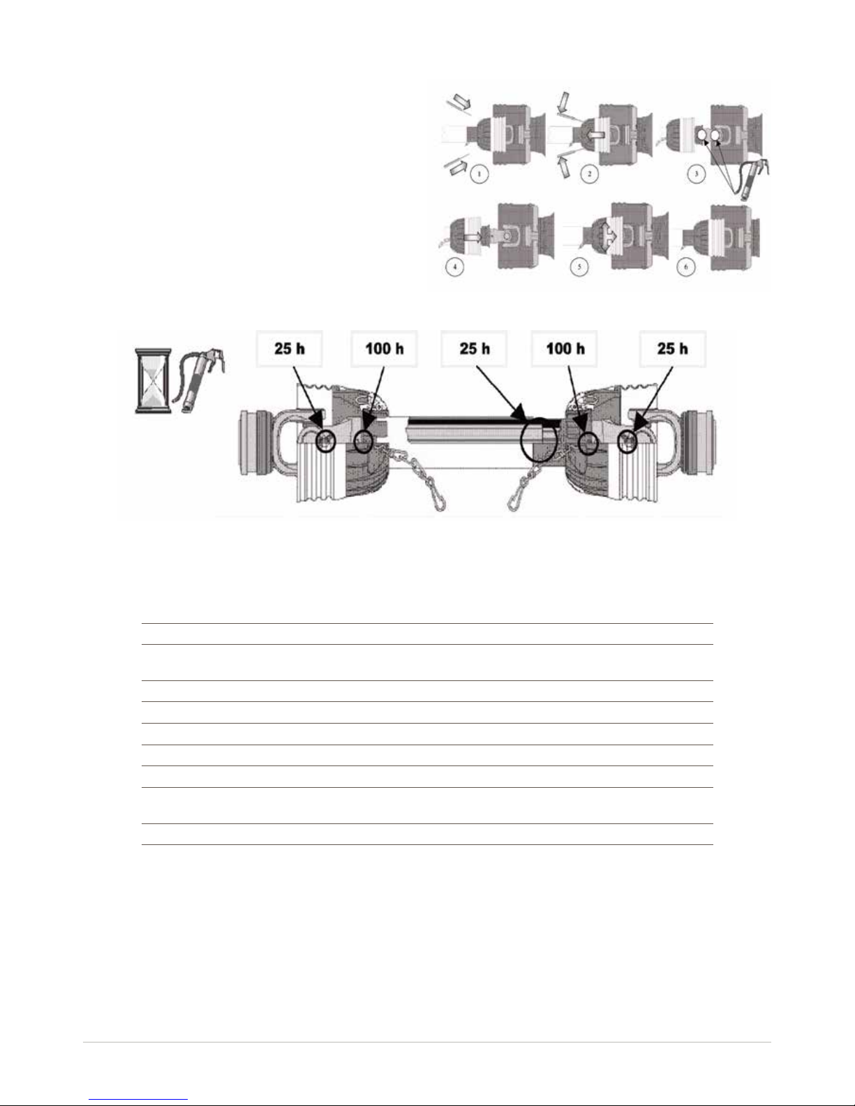
PTO Shaft Maintenance
Guard Removal and Yoke End Greasing
1. Prise back locking tabs
2. Pull back PTO Guard
3. Grease points as shown
4. Push Guard into position
5. Click into place
6. Tie check chain
PTO Guard Greasing Intervals
Maintenance Schedule
Check the following:
Initially 8 Hours 50 Hours 250 Hours
Grease the rotary shaft supports ● ●
Check the condition of the driveline and grease the
journals ● ●
Grease the wheel axles ● ●
Grease the catcher pivots ● ●
Check the belt tension ● ●
Check the oil in the gearbox ● ●
Check the knives for wear. Replace if necessary ● ●
Demount and clean the driveline. Cover sliding parts
with grease. Check all nuts and bolts are tightened. ● ●
Change the oil in the gearbox ● ●
All nuts and bolts in the transmission including PTO Shafts, Gearboxes & wheel nuts should be checked for tightness after mowing at the following intervals:
1st 50 acres,
1st 100 acres,
1st 250 acres and every 250 acres thereafter.
Lubricate moveable mechanical joints when required
Page 14
10
www.major-equipment.com
Changing the gearbox oil
The used oil is a pollutant and must be disposed of correctly. Pour it into a suitable container and take it to
the special oil collection points
• Check the oil in the gearbox
• Check the level of the lubricant through the plug; the oil must reach the lower edge of the hole of level plug.
• Change the rst oil ll after the rst 50 hours service.
• Following this, the oil should be changed after every 250 hours service. View table below for recommended oil &
grease types.
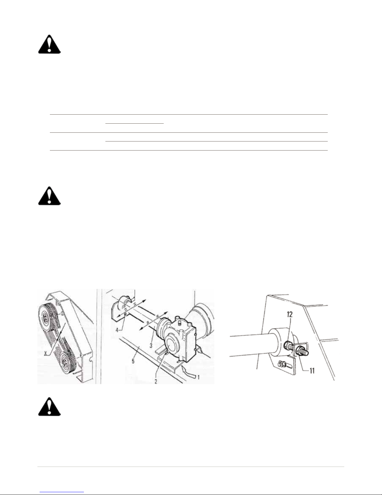
Belt Tension Adjustment
Always switch off the tractor engine, engage the parking brake and disengage the PTO before working on
the drive belts. When possible, such operations should only be carried out after the mower has been disconnected from the tractor
1. Demount the protective casing and check yielding “x” of each belt. Proceed in the following way if belt give
exceeds these values:
2. Slacken bolts “1” that x the gearbox and bolt “4” (option) that locks the chassis extension in place.
3. Release check nut “11” of the belt tensioning screw.
4. Work on screw “12” until obtaining the right belt tension, then tighten the check nut again.
5. Shift the gearbox in the same direction and to the same extent in order to re-align extension tube “3” with the
chassis “5”.
6. Lock the bolts “1” xing gearbox “2” to the chassis together with the bolt xing extension “4”.
AGIP ESSO IP SHELL
Gearbox Oil
ROTRA MP85W/140
Gearoil EP320 Mellana Oil 460 Amala Oil 460
BLASIA 460
Grease
Grease 30 Beacom Atnesia Super Grease
Grumu3 E.P.3 GR3 R3
Make sure the belts are intact, that they are not cracked and do not have ragged edges. If this is not the
case, replace them with new belts.
Page 15

11
www.major-equipment.com
Checking and Replacing Blades
It is advisable to replace all the blades at the same time to prevent the machine vibrating. When mounting
the new blades, make sure the cutting edges are positioned in the direction the rotor rotates in.
1. Place the machine at a comfortable height and lock it in position with sufcient support to guarantee the operator’s
safety. Prevent the blade rotating by locking the shaft with a key (the shaft is designed for this with two at areas immediately above the blade).
2. Using the key, unscrew the nut 1 and remove the blade.
3. Check the state of wear of the pin and the nut and, if necessary, replace them.
4. Mount the new blade, screw in the nut “1” fully and with force, keeping the shaft locked at the same time as described above.
Storing the machine for long periods of time
1. Clean all dirt from the machine. Take particular care to remove any foreign bodies from the blades.
2. Park the mower on a at surface, in a sheltered place inaccessible to either children or animals in a stable position
to prevent it from moving (for this purpose it is advisable to stop the wheels with wedges or other suitable means), fall-
ing or being tted over etc.
3. Check that the weight of the machine is not too heavy for the surface on which it rests
Disposing of the Machine
When scrapping the machine, the procedure to adopt is as follows: remember that it is almost completely made
of ferrous material. The only potentially polluting components on the machine are the lubricants. To prevent them
from polluting the environment, spread a waterproof tarpaulin on the ground, position the machine on this and then
drain out the lubricants, which must be collected in suitable containers. Now dismantle the machine, separating the
components in the following way:
Painted parts;
Ferrous parts;
Plastic parts;
Rubber parts.
Contact those companies that are legally authorised to dispose of such materials.
Trouble Shooting
Fault Cause Remedy
Leaves a streak of
uncut or partially cut
grass
Blades dull or bent Replace blades
Carrier RPM too low Use correct PTO speed
Field conditions are so wet that the tractor
tire is pushing grass into mud
Too wet to mow. Stop operation and wait until it
is drier
Ground speed too fast Reduce ground speed by shifting to a lower gear
Grass is down from previous weather
conditions
Mow in only one direction
Possible build-up materials under mower Clean mower
Blades mounted incorrectly (cutting edge
against direction rotation)
Change blades so that cutting edge is facing
correct rotation.
Material discharges
from mower unevenly;
bunches of material
along with swath
Material too high and too much material
Reduce ground speed but maintain 540rpm at
tractor PTO or make two passes over material.
Raise mower for the rst pass and lower to
desired height for the second and cut a 90
degree angle to rst pass
Grass wet
Allow grass to dry before mowing. Slow ground
speed of tractor but keep engine running at full
PTO rpm. Cutting lower will help
Page 16

12
www.major-equipment.com
Fault Cause Remedy
Gearbox overheating
Low on lubricant Fill to proper level
Improper type lubricant Replace with proper lubricant
Excessive grass / debris build-up around
gearbox
Remove grass, etc from machine
Blade is scalping
ground
Mower too low Raise mower-reset wheels
Field is ridged Cut eld at a different angle
Field is too wet Stop and wait until it is dried
Mower will not cut. Shear bolt sheared Install new shear bolt
Blades wear too fast
Cutting in sandy conditions Increase cutting height
Cutting in rocky conditions Increase cutting height
Blades hitting the ground Increase cutting height
Mower seems to
require excessive
power
Advancing into grass too rapidly Reduce forward travel speed
Hitting ground Raise mower and reset wheels
Worn or dull blades Sharpen or replace blades
Tractor not large enough Use larger horsepower tractor
Excessive vibration
Check gearbox bolts Tighten if loose
Check for loose nuts on blades Tighten if loose
Blade broken Replace blades, in set
New blade or bolts matched with worn blade
or bolts
Replace blades or bolts in sets
Drivelines not phased correctly. Implement
and tractor yokes must be in line
Phase the driveline. Replace if necessary
Noisy machine
Worn bearing Replace bearings
Low oil in gearbox Check level and add oil
Loose Parts Check all bolts are fully tightened
Wrong PTO rpm rate Check PTO rate & adjust as necessary
Rotors bent / broken Replace bent or missing blades
Bent PTO shaft Check PTO shafts are aligned correctly
Check output shaft on gearboxes are not bent
Check driveline between gearboxes is aligned.
Gearbox leaking
Damaged oil seal Replace seal
Bent shaft Replace oil seal and shaft
Shaft rough in oil seal area Replace or repair shaft
Oil seal installed incorrectly Replace seal
Oil seal not sealing in the housing
Replace seal or use a sealant on outside
diameter of seal
Oil level too high Drain oil to proper level
Hole in gearbox Replace the gearbox
Gasket damaged Replace gasket
Bolts loose Tighten bolts
Page 17
13
www.major-equipment.com
101018
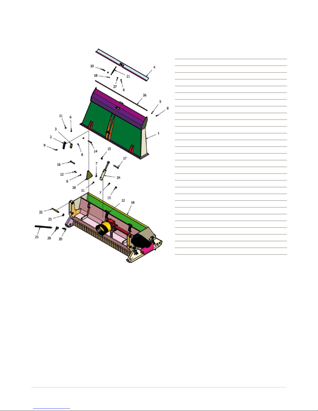
Chute Assembly
Spare Parts
Item Part No Description Qty
1 19TC-CV1 OUTLET CHUTE 1
2 19TC-CV2 CHUTE HINGE DIA 16 3
3 19TC-CV3 HINGE SPACER 3
4 19TC-CV30 CHUTE TOP FLAP 1
5 FWM12 M12 FLAT WASHER 2
6 FWM16 M16 FLAT WASHER 8
7 FWM20 M20 FLAT WASHER 2
8 M12 M12 NYLOC NUT 10
9 M12x40BZP M12x40 BOLT 6
10 M12x60BZP M12x60 BOLT 2
11 M16 M16 NYLOC NUT 7
12 M16x110BZP M16x110 BOLT 1
13 M16x40SZP M16x40 SET BOLT 4
14 M16x90BZP M16x90 BOLT 2
15 M20 M20 NYLOC NUT 2
16 M20x110BZP M20x110 BOLT 1
17 M20x120BZP M20x120 BOLT 1
18 M8 M8 NYLOC NUT 1
19 MT2000GA MT2000 FLAIL ASSEMBLY 1
20 NT29A 1/2” “D” SHACKLE 4
21 S11074 TURNBUCKLE DIA 11xM8 1
22 S15707 CAT 1/2 LINK PIN 4
23 S3546 LINCH PIN DIA 9.5 4
24 SC75-RAM_B SWEEPER RAM 1
25 SS-CHAIN 3/8” CHAIN STRAP 2
26 19TC-CV35 FLAP PIVOT SHAFT 1
27 8SM9-3 BLADE BACK SPACER 4
28 19TC-L10 RAM PIVOT MOUNT 2
Page 18
14
www.major-equipment.com
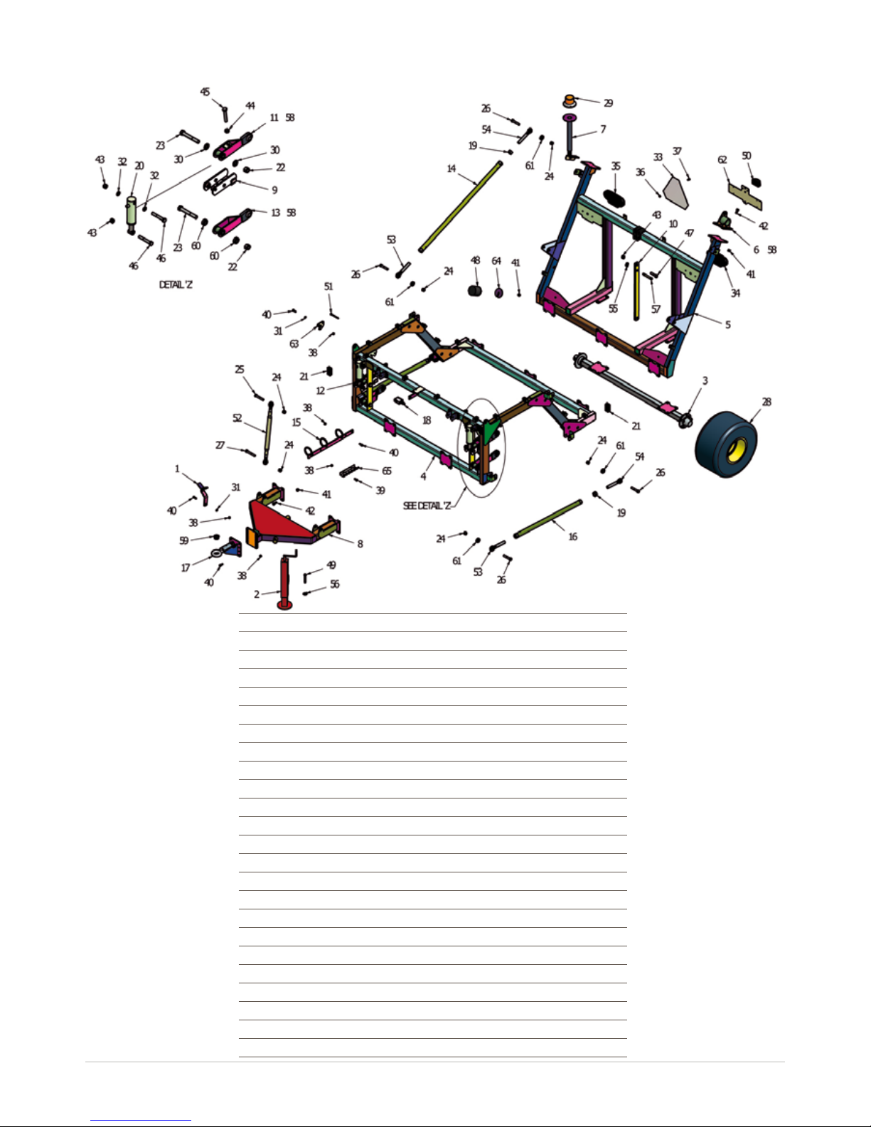
Item Part No Description Qty
1 12DB-030 PTO STAND 1
2 12GMJK-1 RM PARKING JACK 1
3 19TC-A02 CATCHER AXLE (1700) 1
4 19TC-B01 FLAIL BOGEY 1
5 19TC-B50 AXLE BOGEY 1
6 19TC-B80 PIVOT MOUNT 2
7 19TC-BCN01 CATCHER BEACON STAND 1
8 19TC-D01 FC2000 DRAWBAR 1
9 19TC-L20 FLAIL LIFT SHOE 2
10 19TC-L30 LOCK ARM LINK 1
11 19TC-L40 PARALLEL LINK (LH) 1
12 19TC-L40H PARALLEL LINK (RH) 1
13 19TC-L45 PARALLEL LINK (LOWER) 2
14 19TC-L50 TIE BAR 2
15 2TKBC-2 CABLE LOCATION BAR 1
16 AGIMF040 TIE BAR 2
17 RTE-01 ROTARY HITCH EYE 1
18 002070000M518 PRESSURE RELIEF VALVE 1
19 118CHEX 1 1/8” UNC PLAIN NUT 4
20 12D-RAM_B DRAWBAR RAM 2
21 199195 RECT 100x50 INSERT 4
22 1F 1” FINE NYLOC NUT 4
23 1x7FBZP 1”x7” FINE BOLT 4
Bogey Assembly
Page 19

15
www.major-equipment.com
Item Part No Description Qty
24 34F 3/4” FINE NYLOC NUT 12
25 34x412FBZP 3/4”x4 1/2” FINE BOLT 2
26 34x4FBZP 3/4”x4” FINE BOLT 8
27 34x5FBZP 3/4”x5” FINE BOLT 2
28 3605512 DIA 695x345mm 2
29 DA49800101 LED BEACON 1
30 FW1 DIA 1” FLAT WASHER 4
31 FWM12 M12 FLAT WASHER 3
32 FWM20 M20 FLAT WASHER 4
33 Gras-128 SLOW MOVING VEHICLE 1
34 LED-837-LH LIGHT KIT (LH) 88164 1
35 LED-837-RH LIGHT KIT (RH) 88164 1
36 M10 M10 NYLOC NUT 4
37 M10x20SZP M10x20 SET BOLT 4
38 M12 M12 NYLOC NUT 15
39 M12x30SZP M12x30 SET BOLT 2
40 M12x35BZP M12x35 BOLT 13
41 M16 M16 NYLOC NUT 38
42 M16x40SZP M16x40 SET BOLT 36
43 M20 M20 NYLOC NUT 5
44 M20HEX M20 PLAIN NUT 2
45 M20x120SZP M20x120 SET BOLT 2
46 M20x130BZP M20x130 BOLT 4
47 M20x80BZP M20x80 BOLT 1
48 MOT10 DIA 105x100 BUFFER 2
49 S15501 CAT 0 PIN DIA 16x97mm 1
50 S2015 LIGHT-NUMBER PLATE 1
51 S272 SHAFT LOCK PIN DIA 11 2
52 S316-A CAT 1-1 TOP LINK 2
53 S342 TOP LINK DIA 3/4”x1 1/8” (LH) 4
54 S343 TOP LINK DIA 3/4”x1 1/8” (RH) 4
55 S3546 LINCH PIN DIA 9.5 1
56 S37 LINCH PIN DIA 6 1
57 S74 CAT 1 PIN DIA 19x102mm 1
58 S820 GREASE NIPPLE 1/8” STR 6
59 S8561 TOW EYE BUSH 1
60 BSW-R1 SPACER RING 4
61 TA-FBB1 RAM MOUNT REINF” 8
62 19TC-B31 REG-PLATE MOUNT 1
63 19TC-L11 TRANSPORT LATCH 2
64 8T19 BUFFER SPACER 2
65 TA-HCM04 CABLE MOUNT 1
Page 20
16
www.major-equipment.com
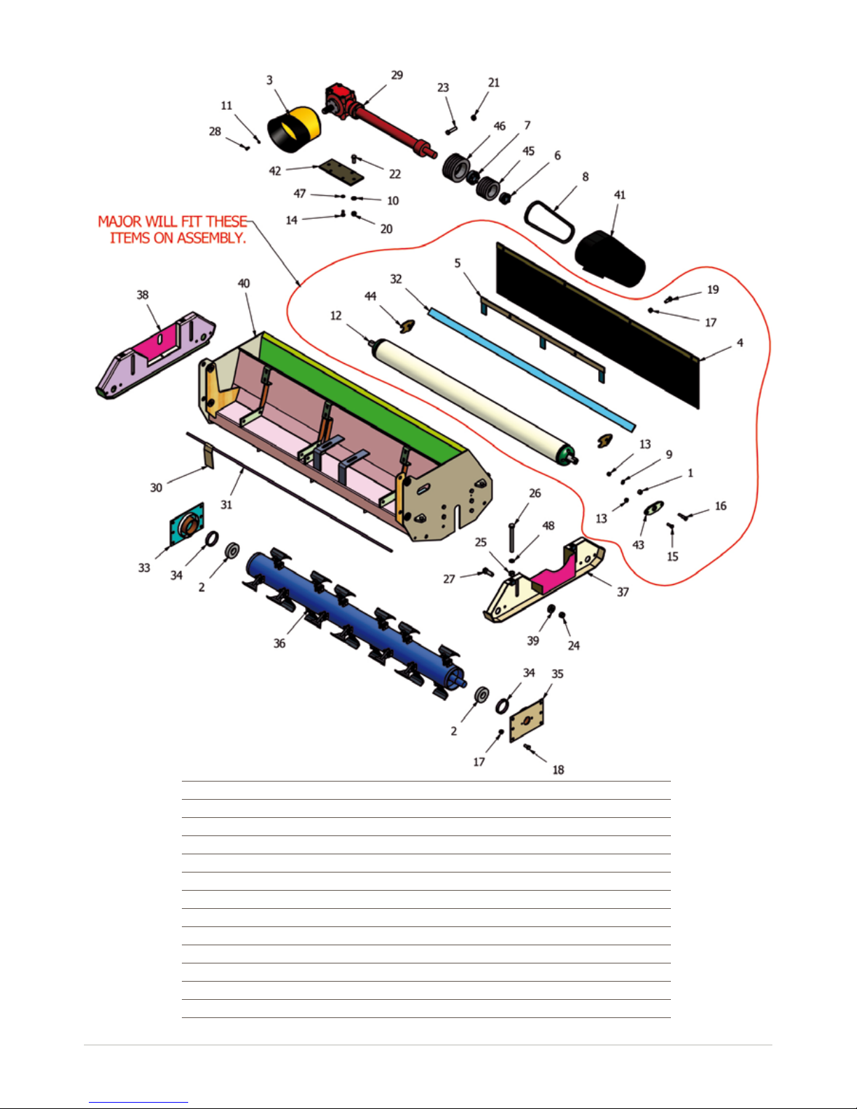
Flail Assembly
Item Part No Description Qty
1 12T-BBS BLADE BACK SPACER 2
2 1309 100x45x25 DOUBLE ROW BALL 2
3 190545 PTO GUARD (EXTENDED OVAL) 1
4 19TC-F10 CATCHER RUBBER FLAP 1
5 19TC-F20 FLAP SUPPORT 1
6 40-65-E15 CLAMPEAST LOCK 15 40/65 1
7 40-80-E15 CLAMPEAST LOCK 15 40/80 1
8 B17-50 B17 BELTx1315mm 4
9 FWM12 M12 FLAT WASHER 2
10 FWM16 M16 FLAT WASHER 2
11 FWM8 M8 FLAT WASHER 4
12 GM63-ROL 6300 ROLLER 1
Page 21
17
www.major-equipment.com
Item Part No Description Qty
13 M12 M12 NYLOC NUT 4
14 M12x30SZP M12x30 SET BOLT 4
15 M12x35BZP M12x35 BOLT 2
16 M12x60BZP M12x60 BOLT 2
17 M14 M14 NYLOC NUT 18
18 M14x30SZP M14x30 SET BOLT 12
19 M14x40BZP M14x40 BOLT 4
20 M16 M16 NYLOC NUT 2
21 M16HEX M16 PLAIN NUT 1
22 M16x40SZP M16x40 SET BOLT 2
23 M16x70SZP M16x70 SET BOLT 1
24 M20 M20 NYLOC NUT 4
25 M20HEX M20 PLAIN NUT 4
26 M20x200SZP M20x200 SET BOLT 4
27 M20x60BZP M20x60 BOLT 4
28 M8x16SZP M8x16 SET BOLT 4
29 MT12-GBOX “T” BOX RATIO 4.12 1
30 MT12GRD02 70mm FLAP GUARD 26
31 MT12GRD03 FLAP GUARD SHAFT 1
32 MT12ROL12 FC2000 SCRAPER 1
33 MT12RT10 BRG HOUSING (NON-DRIVE) 1
34 MT12RT15 BRG SPACER 2
35 MT12RT17 BRG HOUSING (DRIVE) 1
36 MT12RTGAF FLAIL ROTOR ASSY 1
37 MT20-SKD20 CATCHER SKID (LH) 1
38 MT20-SKD21 CATCHER SKID (RH) 1
39 MT20-SKD30 SKID CLAMP WASHER 4
40 MT20B001 COLLECTOR FLAIL BODY 1
41 MT20B008 BELT GUARD 1
42 MT20B017 GBOX MOUNT 1
43 RM-RSN2 ROLLER MOUNT 2
44 RM-RSN4 SCRAPER MOUNT 2
45 68096900 SPB 125 QUAD PULLEY (SPB-125B) 1
46 68060500 SPB 160 QUAD PULLEY (SPB-160B) 1
47 SWM12 M12 SPRING WASHER 4
48 SWM20 M20 SPRING WASHER 4
49 (not
pictured)
V601210CEC02RW6 V60 SHAFT WIDE ANGLE / SLIP CLUTCH 1
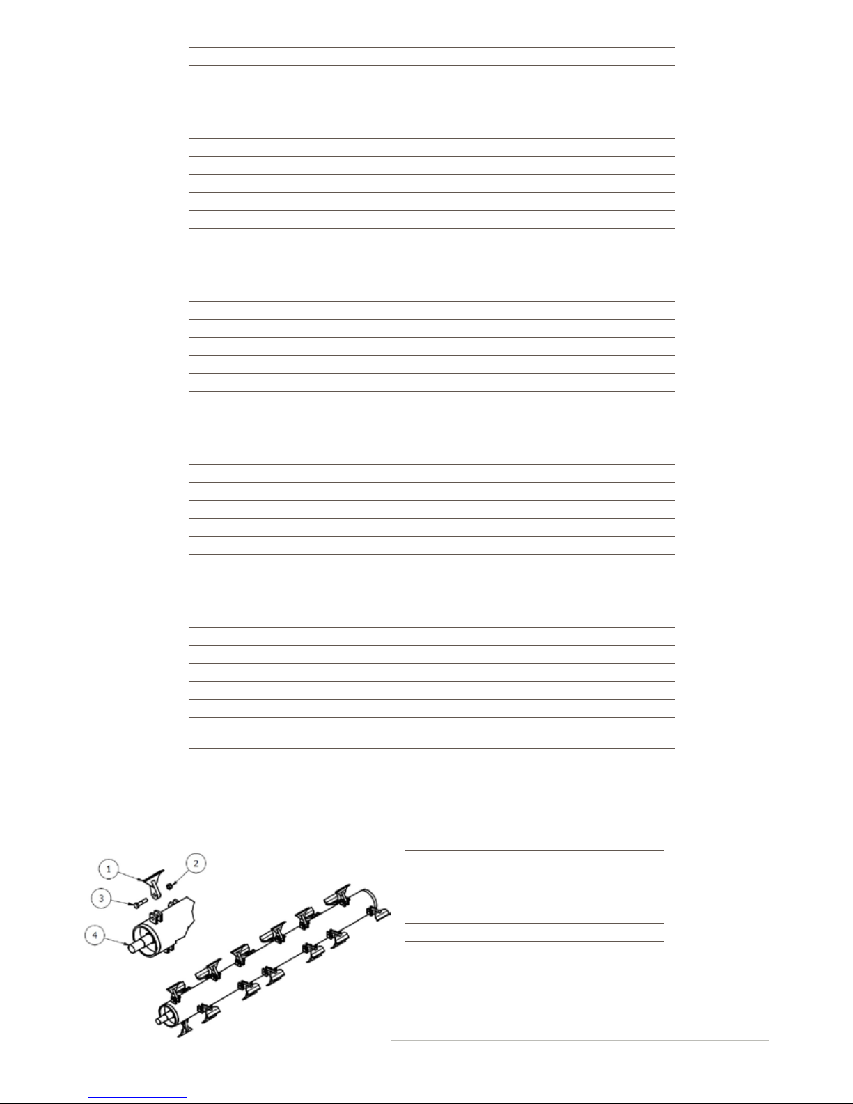
Item Part No Description Qty
1 12014400 FLAIL HAMMER 24
2 M14 M14 NYLOC NUT 24
3 M14x60BZP M14x60 BOLT 24
4 MT12RT05 FLAIL ROTOR 1
Rotor assembly (MT12RTGAF)
Page 22
18
www.major-equipment.com
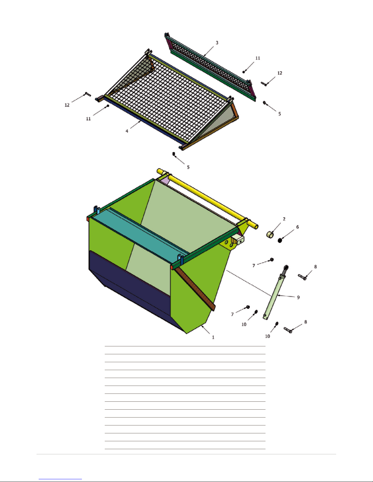
Catcher Assembly
Item Part No Description Qty
1 19TC-C01 MJ2000 HOPPER 1
2 19TC-C23 SPACER TUBE 2
3 19TC-LD01 HOPPER REAR LID 1
4 19TC-LD10 HOPPER TOP LID 1
5 111347 RECT 50x25 INSERT (POL) 8
6 199269 DIA 57.5-61.5mm INSERT 2
7 1F 1” FINE NYLOC NUT 4
8 1x5FBZP 1”x5” FINE BOLT 4
9 AGI2RAM_B RAM 2
10 FW1 DIA 1” FLAT WASHER 4
11 M16 M16 NYLOC NUT 4
12 M16x90BZP M16x90 BOLT 4
Page 23
19
www.major-equipment.com
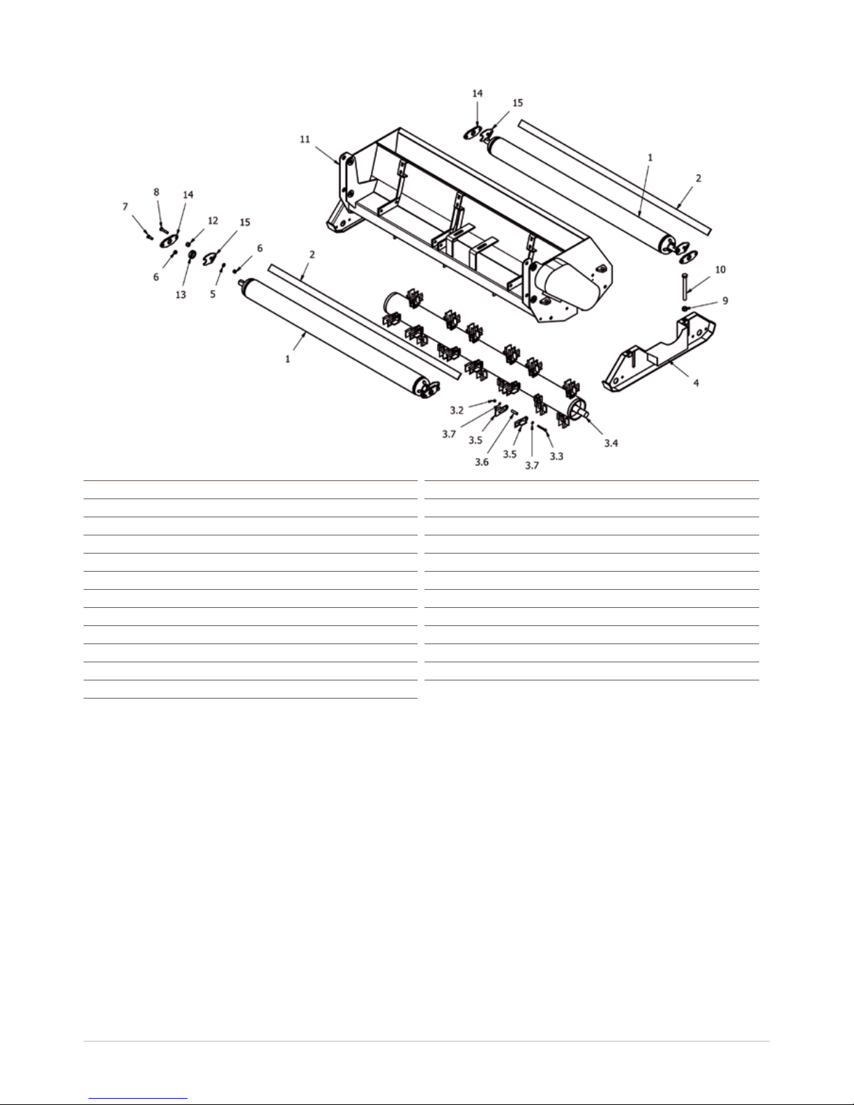
Scarier Assembly
Item Part No Description Qty
1 GM63-ROL 6300 ROLLER 2
2 MT12ROL12 FC2000 SCRAPER 2
3 MT12RTGAS SCARIFIER ROTOR ASSY 1
3.2 M8 M8 NYLOC NUT 24
3.3 M8x70BZP M8x70 BOLT 24
3.4 MT12RT05 FLAIL ROTOR 1
3.5 MT20SC01 FC2000 SCARIFIER BLADE 48
3.6 MT20SC02 SCARIFIER BLADE BUSH 24
3.7 FWM8 M8 FLAT WASHER 48
4 MT20-SKD20 CATCHER SKID (LH) 1
5 FWM12 M12 FLAT WASHER 4
Item Part No Description Qty
6 M12 M12 NYLOC NUT 8
7 M12x35BZP M12x35 BOLT 4
8 M12x60BZP M12x60 BOLT 4
9 M20HEX M20 PLAIN NUT 4
10 M20x200SZP M20x200 SET BOLT 4
11 MT20B001 COLLECTOR FLAIL BODY 1
12 12T-BBS BLADE BACK SPACER 4
13 RM-RSN3 SHAFT COLLAR DIA 35 4
14 RM-RSN2 ROLLER MOUNT 4
15 RM-RSN4 SCRAPER MOUNT 4
Page 24
20
www.major-equipment.com
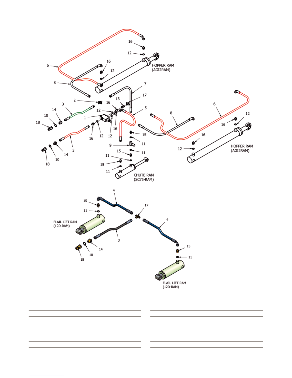
Hydraulics
Item Part No Description Qty
1 002070000M518 PRESSURE RELIEF VALVE 1
2 14CROSS 1/4” M/M/M/M CONNECTOR 1
3 2000FC-HOSE-A 1/4”x2000mm Str to Str 3
4 2000FC-HOSE-B 1/4”x1300mm Str to Block 90 2
5 2000FC-HOSE-C 1/4”x900mm Str to Block 90 1
6 2000FC-HOSE-D 1/4”x4450mm Str to Block 90 2
7 2000FC-HOSE-E 1/4”x600mm Str to Str 1
8 2000FC-HOSE-F 1/4”x3800mm Str to Block 90 2
9 201011 1/4” 1251 NEEDLE VALVE (BLUE) 1
Item Part No Description Qty
10 EDOW12 1/2” DOWTY WASHER 3
11 EDOW14 1/4” DOWTY WASHER 6
12 EDOW38 3/8” DOWTY WASHER 7
13 EFF14 1/4” F/F CONNECTOR 1
14 EMM1214 1/2-14” M/M CONNECTOR 3
15 EMM14 1/4” M/M CONNECTOR 5
16 EMM3814 3/8-1/4” M/M CONNECTOR 7
17 EMMMT14 1/4” M/M/M CONNECTOR 2
18 QRM12 1/2” QUICK RELEASE MALE 3
Page 25
Warranty: This machine is guaranteed for 12 months. No warranty is given where the machine is being used as a hire machine.
Warranty is against faulty workmanship or parts, with the exception of components not of MAJOR’S manufacture or design, i.e.
hydraulic components, universally jointed shafts, chains and tyres, etc., which are subject to the original manufacturers conditions.
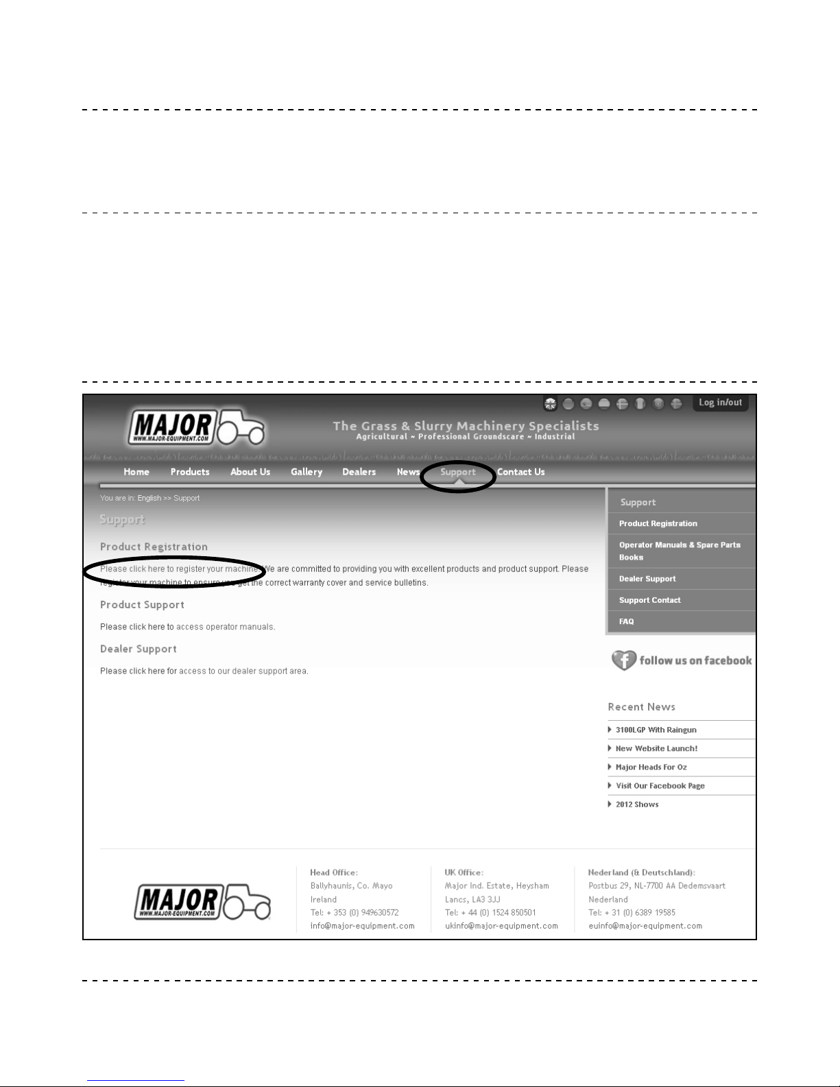
To register your machine for warranty, please go to the support section of our website www.major-equipment.com and enter your
details.
Page 26

HEAD OFFICE
Major Equipment Intl Ltd
Ballyhaunis, Co Mayo
Ireland
Tel: +353 (0) 9496 30572
UK OFFICE
Major Equipment Ltd
Major Ind. Estate, Heysham,
Lancs, LA3 3JJ, UK
Tel: +44 (0) 1524 850501
Netherlands & Germany OFFICE
Major Equipment Intl Ltd
Postbus 29, NL-7700 AA
Dedemsvaart, Nederland
Tel: + 31 (0) 6389 19585
 Loading...