

Page 1
1
MJ9900
TECHNICAL MANUAL
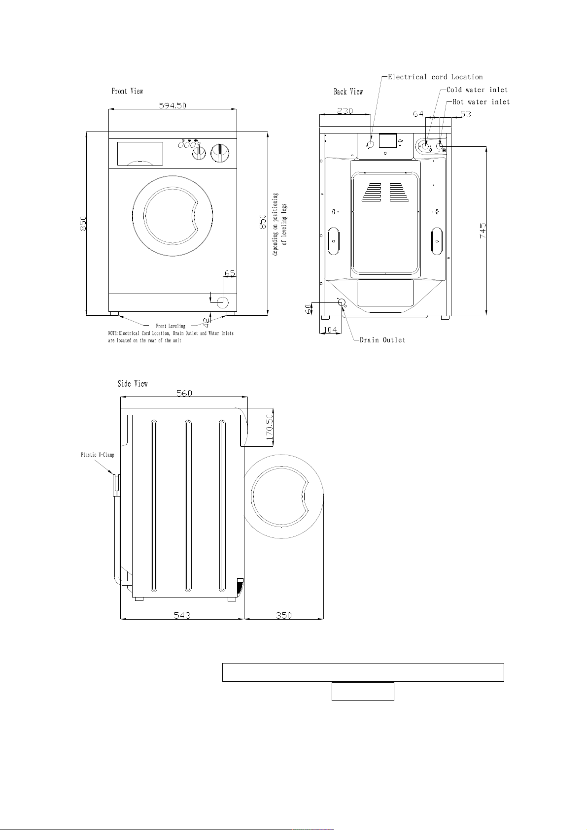
MJ9900 installation dimension
Page 2
2
Your machine, has a solution to every
problem
We have put together here a few questions which may
come to mind when you start using your machine, you will
see for yourself that your new washer dryer can give a
convincing and state of the art reply to all of them.
What to do if
Page 3

3
This machine has been designed to adapt the washing
process to all types of fabric and to treat your washing in
the most delicate way possible. In any case, we would
advise you to take certain basic precaution:
Mend any tears in items before washing them.
Sew back on any buttons that are loose.
Close any zips.
Do not machine wash items without hems.
Empty the pockets of jackets, shirts and trousers and
turn them inside out.
Button up any bag-like items that could hold water
(pillow cases for example).
Large items like sheets and table cloths should be
put in loosely and not folded.
Turn shirts inside out.
Apart from the performance
of the machine, a successful
wash also depends on the quality of the detergent
used. There are numerous excellent brands
on the market. For your machine to work best, we
suggest you use non- foam detergents that are
specifically for automatic washer dryer. If you are
washing synthetics or woollens, you should use
detergents made specially for them.
Above all, avoid using dry cleaning solvents such
as trichloroethylene or similar products.
It depends, In some areas the water is vary hard and it
leaves calcium deposits on both the heating element of
the washer dryer and on the washing itself. Which over
time damage both. In such case, it is a good idea to mix
a water softener, or decalcifier, in with your detergent to
dissolve the calcium.
Your machine, has a solution to every
problem
Every time you have particularly dirty items to wash,
when you think it would help them to have a longer
wash with more detergent.
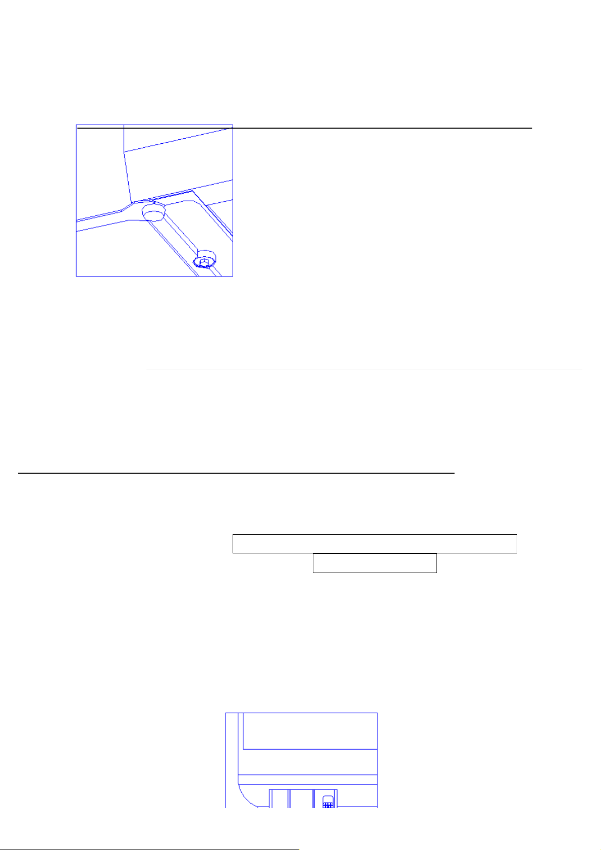
The most important thing is for it to be perfectly level.
This is why it has adjustable feet (fig.1) so as to
eliminate any imperfections in the floor.
1. Can washing
damage my
clothes?
2.What sort of
detergent should
I use?
3.Is it all right if
use a water
softener?
4.When should I
use the prewash?
5.What is the best
position for my
washer-dryer?
Page 4
4
We would also advise you to place your washer-dryer in such a way that there is
some space-even a fraction of an inch-all sides.
(Fig.1)
First of all, remember to switch off the electricity. Then, to
clean the body and any rubber parts use a damp cloth
and a little soap.
Avoid petrol or other solvents at all costs.
If this means that your washer-dryer is going to stay
unused for a long time, then it would be best before
you go to unplug it, close the water tap and leave the
door ajar so as to avoid any unpleasant odours
remaining inside. In fact, it is advisable to leave the
door open during periods of non-use as well.
If you are moving house, there is one simple but very
important thing you should do: Block the drum to save it
from bumps, To do this, put back the blocking screws
that were removed when it was installed.
Maintenance: Four simple precaution
for this machine
Your machine is a washer-dryer that has been designed to last without complicated
maintenance. All the same, we would ask you to take care of a few small matters. If
you follow these four simple rules, we are sure that the washer-dryer machine will
stay your faithful friend and helper for a long, a long time.
1. Ensure that your machine was installed according to the installation manual that
comes with this booklet.
1. Avoid at all costs using solvents either to clean the machine, or to do the wash.
2. Clean the detergent dispenser every so often. This is very simple and should be
done with water. Your machine has an extractable dispenser to make it even
6.How shoulder I
clean my washerdryer?
7.Do I have to take
any particular
when I go on
holiday?
8.---And if I move
house?
Page 5
5
easier. Just pull it upwards and out, as shown in Fig.2
(Fig.2)
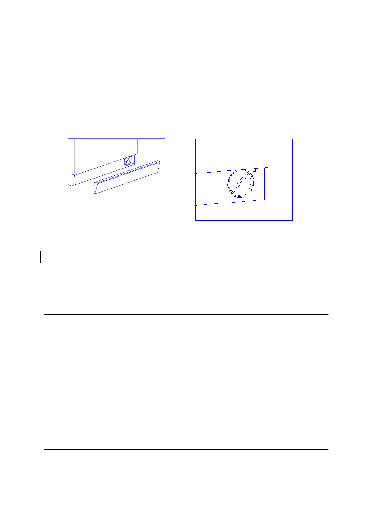
3. Your washer-dryer is equipped with a self-cleaning pump. It is therefore not
necessary to carry out cleaning and maintenance operation. Some objects
however, (such as buttons, coins, etc), may sometimes accidentally drop into the
pimp. Since these cannot be expelled through the drain pipe, they are trapped in a
special “anti-chamber” which can be reached through the front part of pump. Open
the cover of the filter, loose the knob in counter-clockwise rotation, then take out
the filter and clean it with water (see Fig.3 and Fig.4).
(Fig.3) (Fig.4)
Note: Re-assembly the filter carefully after cleaning, ensuring it is fit perfectly
and no water can come inside.
When you do not need a technician----
Even though your washer-dryer has been carefully designed and constructed,
something could still go a miss with your machine. Before rushing to please check
that the operations listed below have been carried out. In many cases you will save
time, money and bother. Our statistics show that many of the calls received by our
service centers could have been avoided with just a little more attention.
Check that:
The plug is pushed right into the main sockets;
The door is closed tight;
The “ON/OFF” button has been pressed.
Check that:
The tap is open and properly connected to the
inlet pipe;
The inlet pipe is not bent.
Check that:
The inlet pipe is placed at least 80cm/32 inches above
ground level.
The washer-dryer
fills and drains
continuously
The washer-dryer
won’t start
The washer-dryer
won’t fill with
water
Page 6

6
Check that:
The inlet pipe is not blocked;
The inlet pipe is not connected at a height more then
1 metre/40 inches above ground level.
Check that:
The detergent being used is meant for
automatic machines and not for washing by
hand;
That the amount used is that shown in this
manual and not more.
Check that:
The transit bolts have been removed (see installation
manual);
The machine is level;
The washing load is according to instructions given in
this booklet.
When you do not need a technician----
Check that:
The plug is fitted firmly into the main socket;
The door is properly closed;
The drying time knob is not in position”0”.
Check that:
The free end of the drain pipe is not under water;
The filter is clean (do not remove the filter while the
washer-dryer is running);
The recommendations for the maximum loads and
drying times have been followed;
The drying time is set at least to 20 minutes;
The water tap is open.
The washer-dryer
will not drain the
water
There is too much
foam in the tub
The washer-dryer
vibrates too much
when spinning
The washer-dryer
is not drying
The washer-dryer
is not drying
efficiently
Page 7
7
WASHING MACHINES
REF.MODELS MJ9900 DESCRIPTION
Page 8

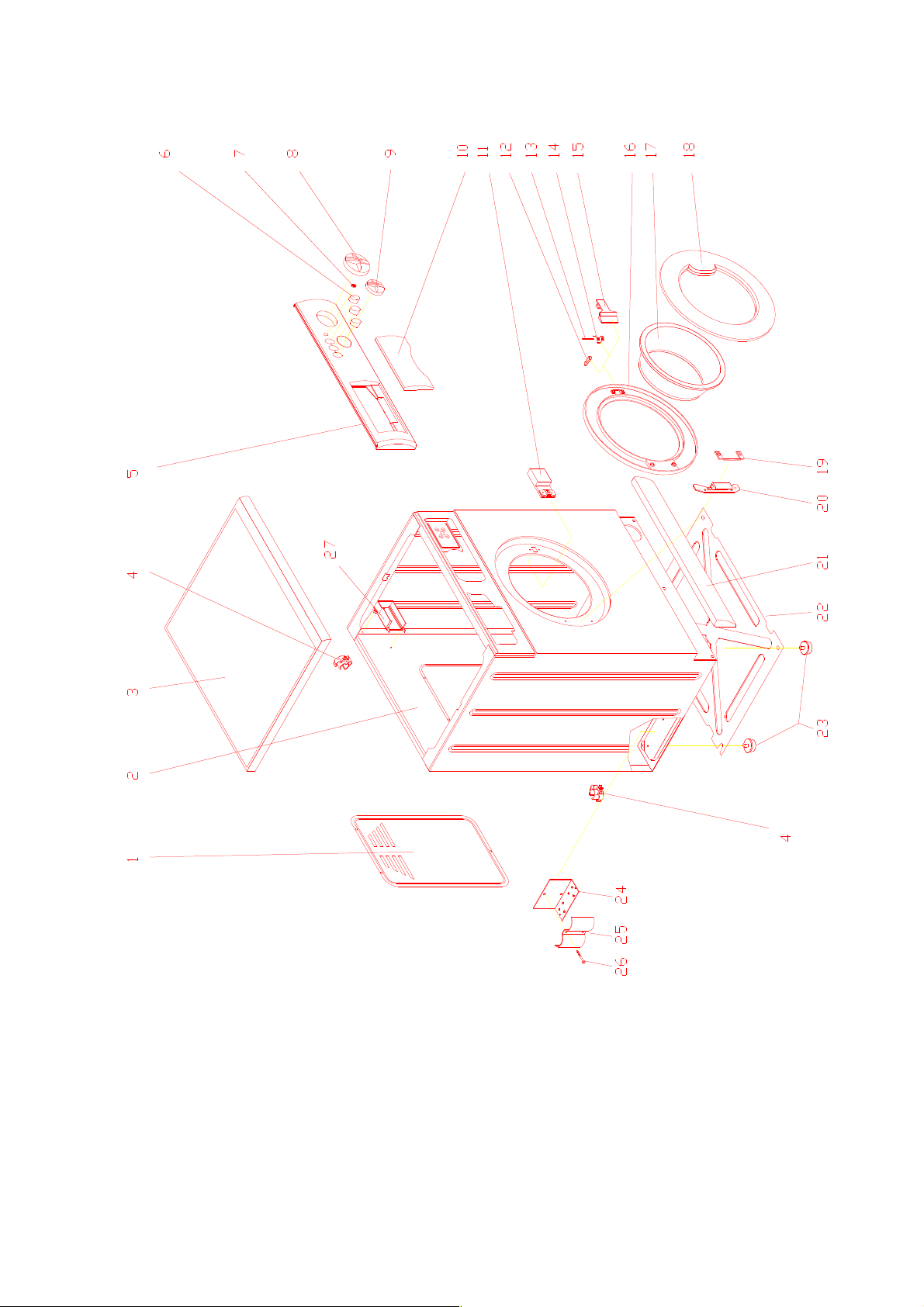
8
01
Back panel
02
Cabinet assembly
03
Top panel assembly
04
Rest for hose and cable
05
Board panel
06
Switch cover
07
Lamp cover
08
Timer (washing) knob
09
Timer (drying) knob
10
Dispenser handle
11
Micro delaying device
12
Porthole catch
13
Porthole catch pin
14
Porthole catch spring
15
Porthole handle
16
Porthole inner frame
17
Porthole glass
18
Porthole frame
19
Support for porthole hinge
20
Porthole hinge
21
Kick plate cover assembly
22
Feet
23
Under panel
24
Support for capacitor
25
Bracket for capacitor
26
screw
27
Support for speed regulator
Page 9
9
Page 10

10
WASHING MACHINES
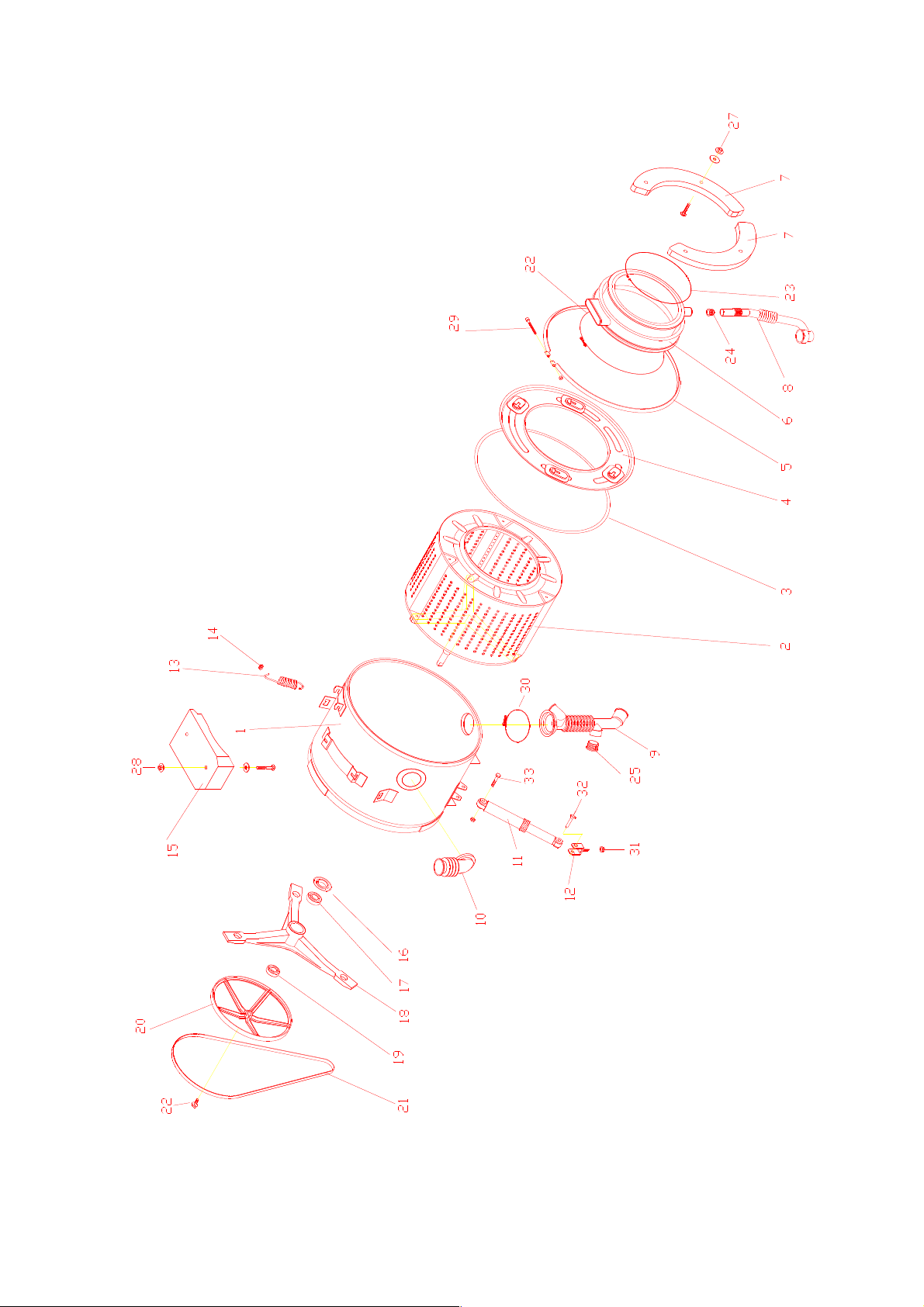
REF.MODELS MJ9900 DESCRIPTION
01
Tub
02
Drum
03
Tub cover gasket
04
Tub front flange
05
“U” bolt
06
Porthole gasket
07
Front counterweight
08
Detergent recovery hose
09
Hose tub to pump
10
Hose dispenser to tub
11
Shock absorber
12
Shock absorber support
13
Tub suspension spring
14
Spring rest
15
Upper counterweight
16
Retaining ring
17
Bearing 6205
18
Tub spider assembly
19
Bearing 6204
20
Driven pulley
21
Ply V belt
22
Blot. Drum pulley fixing
23
Porthole gasket fixing ring
24
Hose connection to porthole
25
Hose connection
26
Porthole gasket and tub fixing ring
27
Bolt M8X45, washer and nut M8
28
Bolt M8X60, washer and nut M8
29
Screw M6X80 nut M6
30
Fix ring for hose of tube and pump Screw
31
Nut-wash combine M6
32
Plastic pin
33
Bolt M10X40 and nut M10
Page 11

11
Page 12

12
WASHING MACHINES
REF.MODELS MJ9900 DESCRIPTION
01
Dry timer
02-05-45
Pressure switch hose
03
1level Pressure switch with over flow
04
2 level pressure switch
06
Wash timer
07
“Y” coupling
08
Transmission to detergent tray
09
Cam follower
10
Bush to timer cam
11
Timer cam
12
Cable assembly
13
Pump
14-15
Capacitor
16
Motor
17
Nut M6
18
Motor spacer
19
Bush for motor
20
Motor bolt M6X212
21
Support for drain hose
22
Drain hose
23
Wiring assembly
24
Hopper
25
Pipe for solenoid valve
26
“T” coupling
27
Inlet water assembly
28
Detergent tray
29
Cover for detergent tray
30
Lamp
31
Hopper cover
32
Dispenser spring
33
Transmission for dispenser
34
Ejector guide
35
Ejector
36-37-38
Switch_switch_power switch
39
Double head solenoid valve (cool)
40
Solenoid valve (heat)
41
Pressure reducing valve
42
Sponge
43
Air trap
44
Clamp for air trap
46
Speed regulator
47
3 poles terminal board
48
Tube between solenoid valve and condenser
Page 13

13
Page 14

14
WASHING MACHINES
REF.MODELS MJ9900 DESCRIPTION
01
Fan motor
02
The wire with fuse
03
Thermostat 2TT NC 125/85
04-16
Upper body of blower
05
Reflecting screen WDM
06
Heating element
07
Gasket of blower bode WDM
08
Lower body of blower
09
Zipper for porthole gasket and blower
10
Condenser
11
Condenser-tube gasket
12
Hose condenser to tub
13-14
Flux adjusting parts
15
Condenser blower gasket
16,17
Fan group
18
Clips
Page 15

151617
Page 16

Page 17

Timer removal and installation
Removal:
1_ Disconnect power from machine.
2_ Remove the top panel assembly by unfixing the two screws ST3.5x13.
timer for 9900\9000V\9200W
3_ Pull out the timer knob. Round the cam clockwise, let you can see two M5x5 screws,
4_ Unfix two screws size M5x5, and then take out the timer from cam bush.
5_ Pull out all housing of the wiring from the terminals of timer.
6_ Change the new timer as fig above, plug the wire housings to timer terminals, pay
attention to color of housing, the black housing plug to terminal column with a black
point nearby, and then yellow to yellow_green to green and so on.
7_ Plug the time shaft to cam bush, pay attention to the angle and position, be sure that the
section shape is corresponding with the cam bush hole.
8_ Fix time to cabinet using two screw size M5x5, let the wiring at proper position, if the
hole can not be seen, turn cam clockwise an angle to expose the screw hole.
9_ Amount the timer knob, Power on machine, test the machine , insure it can work in
manner indicated in control panel.
10_ Fix the top cover assembly to machine.
11_ Complete.
Motor check and how to change it
1_motor test
Page 18

18
8P socket
M4 ground
connection
Page 19

19
8P connector
Terminal
Description
Resistance
1-2
Auxiliary winding (spin)
5.3-5.8_
1-6
Primary winding (spin)
2.8-3.2_
2-6
Aux and primary winding (spin)
7.7-8.01_
3-5
Common and aux winding((wash)
9.6-9.7_
5-7
Common and primary winding (wash)
9.6-9.7_
3-7
Aux and primary winding(wash)
12.1-12.4_
4-8
Tachometer
23.3-24.1_
2_How to change the motor
1_ Disconnect power and water supply from machine.
2_ Move the machine to an open space for repair.
3_ Remove back panel by removing three size SD3.5x13mm
screws.
4_ Tilt the machine, wrest the two front feet two rounds
anticlockwise.
5_ Tilt the machine forward, unscrew tow back feet, and then take
out under panel.
6_ Fetch the V-belt from the pulley, and Tilt the washing machine
forwards.
7_ Take off 8P plug housing and ground terminal of the wirings from
the motor socket.
8_ Use short handle sleeve spanner unscrews right motor bolt size
M6x217 and nuts M6.then pull out bolt.
9_ Unscrew left motor bolt size M6x217 and nut M6, at the same
time with your left hand support the motor in position. Pull out bolt.
Then take out motor from the button of the machine carefully.
10_ Change a new motor one by one at counter step.
11_ Recover the machine and make a test to insure the machine can
work normally.
12_ Complete.
Page 20

20
Micro delaying device
Housing No: MRL of wiring to L terminal of switch_
Housing No: MRN of wiring to N terminal of switch_
Housing No: MRC of wiring to C terminal of switch.
Housing No: IP_IPX of wiring plug to micro switch
Hose dispenser to tub (9000V\9900)
Speed regulator
1_ picture
Micro switch
Page 21

21
2_removal and connection
1_Disconnect power from machine.
2_Remove the top panel assembly by unfixing the two screws
ST3.5x13.
2_ Unfix two screw size SD3.5X13 from the back of cabinet ,take
off the speed regulator support.
3_pull out all terminals from regulator assembly.
4_take out regulator from regulator support.
5_replace a new speed regulator.
6_connect wiring to speed regulator as follows:
Page 22

22
Plug terminal RV1 of wiring to 1 terminal of regulator
Plug terminal RV2 of wiring to 2 terminal of regulator
Plug terminal RVF of wiring to F terminal of regulator
Plug terminal RV3 of wiring to 3 terminal of regulator
Plug terminal RV4 of wiring to 4 terminal of regulator
Plug terminal RV5 of wiring to 5 terminal of regulator
Plug terminal RV6 of wiring to 6 terminal of regulator
Plug terminal RV7 of wiring to 7 terminal of regulator
7_Plug speed regulator to regulator support until clamp in action.
8_Use two screw SD3.5x13 fix regulator assembly to cabinet.
9_Test the machine to sure the machine can work normal.
10_Recovery the top panel assembly.
11_Complete.
How to change pressure switch
This machine has a 1 level pressure switch and 2 level pressure switch.
2 Level pressure
switch
1 level pressure
switch
Page 23

23
A: 2 level pressure switch
1_ Disconnect power and water supply from machine.
2_ Move the machine to an open space for repair.
3_ Remove back panel by removing three size SD3.5x13mm
screws.
4_ Remove screw SD3.5x13; take out 2 level pressure switch from
cabinet.
5_ Pull out all housing of wiring and hose from switch.
6_ Replace a new switch, connect hose to position, move clamp to
proper position.
7_ Connect housings of wiring to switch as fellow:
Housing No: PV11 to 11 terminal of switch,
Housing No: PV12 to 12 terminal of switch,
Housing No: PV13 to 13 terminal of switch,
Housing No: PV21 to 21 terminal of switch,
Housing No: PV22 to 22 terminal of switch,
Housing No: PV23 to 23 terminal of switch,
8_ Fix screw SD3.5x13, amount the switch to cabinet.
9_ Complete.
B: 1 level pressure switch:
The process is same as above, wiring connect as fellow:
Housing No: PV11 to 1 terminal of switch,
Housing No: PV12 to 2 terminal of switch,
Housing No: PV13 to 3 terminal of switch,
Housing No: PV14 to 4 terminal of switch
How to change drying timer
1_Disconnect power from machine.
2_Remove top panel assembly by removing two size SD3.5x13mm
screws.
3_pull out timer knob from control panel.
4_unscrew two screw size M4x6 from control panel.
5_take out drying timer from control panel.
6_pull out all terminals of wiring.
7_change a new timer and connect terminals as fellow:
Plug terminal No: TAA of wiring to “a” terminal of timer,
Plug terminal No: TAA1 of wiring to “a1” terminal of timer,
Plug terminal No: TAB of wiring to “b” terminal of timer,
Plug terminal No: TAB1 of wiring to “b1” terminal of timer,
Plug terminal No: TAC of wiring to “c1” terminal of timer,
Plug ground terminal (green) of wiring to ground terminal of timer,
8_Use two screws size M4x6 amount timer to control panel .
Page 24

24
9_Test machine.
10_Amount top panel assembly.
11_Complete.
Double head valve (cold water) and solenoid valve (hot water)
1_ picture
2_connect valve to wiring
3_resistance test
resistance of coil R=494_
Page 25

25
Fan motor
Connection: Plug terminal MV of wiring to upper terminal of fan motor.
Plug terminal TF of wiring to lower terminal of fan motor.
Hose dispenser to tub (9000V\9900)
Page 26

26
Pump
1_picture
2_connection to wiring
Capacity
1_picture
2_test
C1=80uF C2=80uF
3_connect to wiring
Connect C1, C1X terminals of wiring to C1.
C1
C2
Page 27

27
Connect C2, C2X terminals of wiring to C2.
Fan
Heat element
Page 28

28
Wire with fuse and Thermostat 2TT NC 125/85
17
Connection of dryer
1,plug MV terminal of wiring to upper terminal of fan motor
2,plug TF terminal of wiring to lower terminal of fan motor
3,plug FEX and FE terminals of wiring to terminals with red point
of thermostats
4,plug FDX and FD terminals of wiring to terminals with black
point of thermostats
5,plug RA terminal to a terminal of heater.
Page 29

29
 Loading...