

Page 1
Woodburning Fireplaces
Models: B36LA and B36RA
Installation, Operation and Maintenance Manual
36” Built-in Wood Burning Corner Fireplace with Optional Outside Air and Glass Doors
WARNING: This fireplace has not been tested with an unvented gas log set. To reduce risk
of fire or injury, do not install an unvented gas log set into fireplace.
Report No. MH7603
For Residential Installation
53D9041 1/09 Rev. 2
Page 2

B36LA & B36RA Woodburning Fireplaces
CONTENTS
Congratulations!
You have chosen the finest wood burning fireplace available. Your fireplace has been designed for years of heating
and viewing enjoyment. Please take time to read this entire manual before installing or operating your fireplace.
Table of Contents
Listing and Code Approvals ..........................................................................................................................2
Important Information ...................................................................................................................................3
Operation Guidelines .................................................................................................................................... 4
Product Features ..........................................................................................................................................5
Fireplace Components .................................................................................................................................6
Fireplace Installation ....................................................................................................................................7
Chimney Components ..................................................................................................................................8
Selecting a Location ..................................................................................................................................... 9
Floor Protection .......................................................................................................................................... 10
Clearances .................................................................................................................................................11
Fireplace Installation ..................................................................................................................................12
Mobile Home Installation ............................................................................................................................ 15
Chimney Installation ................................................................................................................................... 16
Chimney Offset and Cap Installation ..........................................................................................................
Outside Combustion Air Precautions and Recommendations ....................................................................
Combustion Air Assembly ...........................................................................................................................
Gas Appliance Installation ..........................................................................................................................
Trim Installation ..........................................................................................................................................
Fireplace Operation ....................................................................................................................................27
Maintenance and Safety ............................................................................................................................. 29
Repair Parts Diagram and List ...................................................................................................................32
Warranty .....................................................................................................................................................
19
22
23
24
25
35
Listing And Code Approvals
The instructions contained in this manual provide the information necessary to install this fireplace in accordance with
Underwriter’s Laboratories requirements and in compliance with the National Fire Protection Association Standard No.
211. Some codes may require the fireplace and chimney be electrically grounded. Before beginning the installation, you
should check with local building officials to obtain required permits and assure compliance with local regulations and
coded. If you encounter problems with code requirements, contact your dealer for assistance.
These Fireplace models are listed by Underwriters Laboratories, Inc. to U.L. 127-standard for factory-built fireplaces.
The design of this fireplace and these instructions complied with applicable safety standard for a factory built fireplace
in effect at the time the fireplace was manufactured. You should be aware, however, that failure to install, operate, and
maintain this or any other factory built fireplace properly can result in a house fire or other occurrences that could cause
deaths, injuries, and property damages. It is very important that the persons installing and/or supervising the installation
of this fireplace have appropriate skills in using the tools and techniques required; and reading and comprehension skills
sufficient to read and follow these instructions. These instructions contain warnings, cautions, and notes to emphasize
important safety information. To assure that safe and satisfactory service is received from this fireplace, please read the
following special notices and all the contents of this manual.
2
53D9041
Page 3

IMPORTANT SAFETY INFORMATION
Installer Owner
Please leave these instructions with the owner. Please retain these instructions for future reference.
1. Read these instructions entirely before beginning any part of the installation. Save these instructions for any future
repairs.
2. Use these instructions as a guide during the installation of the fireplace.
3. Be sure these instructions become the property of and are reviewed by all future users of this fireplace to encourage
proper operation and maintenance.
4. All the parts used with this fireplace system must be installed in accordance with these installation instructions. Failure to do so may be hazardous and will void the warranty.
5. This fireplace and accessories should not be altered in any way that is not specifically recommended in this manu
al.
6. Refer to your local building code for local requirements pertaining to installation of factory-built fireplaces. These
fireplaces are intended for installation and use according to standard NFPA NO.211 of the National Fire Protection
Association.
7. This fireplace must not be installed with a masonry flue.
8. This fireplace and chimney should not be used for venting a wood or coal burning heater or fireplace insert.
WARNING: Do not install a separate solid fuel insert or gas fireplace insert into this fireplace and chimney system
without written authorization.
9. WARNING: Do not pack required air spaces with combustible material or insulation not specifically recommended
for use in such areas.
B36LA & B36RA Woodburning Fireplaces
-
Intended Product Usage
This fireplace is intended for supplemental heating only and is not intended for use as a primary heating system.
The fireplace is designed to sit directly on a combustible floor. The fireplace must be installed with clearances to combustible building materials specified in this manual. Only parts manufactured by MHSC and labeled for use with the fireplace should be used in the installation of this fireplace except for special roof flashings that may be fabricated locally.
The use of improper parts in the installation can be hazardous and voids the warranty offered by MHSC.
This fireplace is designed to burn wood. This fireplace is not designed to burn coal, unplumbed liquid fuels, unplumbed
gaseous fuels or household refuse. Any attempt to burn these fuels in the fireplace can be hazardous.
This fireplace is designed for installation in mobile homes if it is installed in accordance with Figure 32 in this manual,
which includes using and OAC6 combustion air assembly, WB36LR glass door, SVT firestop thimble, and use either the
LLK or RLK louver kit.
WARNING:
CAUTION: If installed in a mobile home, the structural integrity of the floor, wall and ceiling/roof must be maintained.
WARNING: This fireplace and chimney must not be used for venting a solid fuel heater or fireplace insert unless written
authorization is given by MHSC. Failure to heed this warning may cause fire hazard and will void the warranty.
Do not install in a sleeping room of a mobile home.
Improper Installation
Improper installation or use of this fireplace will void the warranty and can cause:
1. Damage to the fireplace from overheating.
2. Hazardous temperatures to develop on combustible materials adjacent to the fireplace or chimney.
3. The emission of smoke, sparks or hazardous gases into the dwelling.
4. Leakage of rain water into the dwelling.
53D9041
3
Page 4

B36LA & B36RA Woodburning Fireplaces
As wood is burned in the fireplace, room air enters the air slot on the lower front edge and circulates
around the firebox.
The air circulation around the firebox serves to cool the fireplace and must not be blocked in any manner. Blocking of the inlet slot or outlet louver will cause the firebox to reach hazardous temperatures.
When an OAC4 combustion air assembly and a combustion air duct are attached to the connecting
point on the left of the fireplace, combustion air may enter the firebox through a dampered opening
behind the side panel. This feature is designed for your benefit to reduce the room air used for combustion and to prevent excessive loss of heat from the room. When the fireplace is in use, this damper
should be open. When the fireplace is not in use, the damper should be closed to prevent cold air from
entering the firebox. The combustion air damper is open when the lever, located on the side of the
firebox is up and closed when the lever is down.
Outside air for combustion is optional unless required by federal, state or local building codes. See the
section of this manual providing the instructions for installation of the combustion air assembly.
Glass doors should be installed to receive the maximum benefit from your fireplace. For large fires, the
maximum heating benefit from the fireplace will be obtained with the doors open due to the high amount
of radiant heat being emitted out of the front opening of the fireplace. With a small fire, or before retiring
in the evenings, it is best to operate the fireplace with the doors closed to prevent excessive room air
form being drawn up the chimney. When the doors are open, the mesh screens should be closed to
help keep burning embers from popping out of the firebox.
The unique design of the fireplace allows the routing of the combustion air duct downward, horizontally
or upward to obtain the outside combustion air. This permits maximum flexibility in planning your installation. Refer to Page 22, Figure 24 for typical installation methods. Be sure to review the precautions
and recommendations in the section of this manual pertaining to outside combustion air assembly.
The fireplace is also equipped with a flue damper, which must be open when the fireplace is in use. The
flue damper control lever is located inside the fireplace. The counterweighted damper is operated by
simply pushing up to open or pulling down to close the damper. When the fireplace is not in use, the
damper should be closed to prevent cold air form entering the chimney as well as preventing warm air
in the room from escaping up the chimney.
NOTE: It is normal for a small amount of smoke to be released from the upper portion of the fireplace
the first few times you use your new fireplace. This results from an oil residue on the metal. Open a
door or window to allow the smoke to escape.
WARNING: Fireplaces equipped with glass doors should be operated only with the doors fully open or
doors fully closed. If doors are left partly open, gas and flame may be drawn out of the fireplace open
ing, creating risks of both fire and smoke.
All fireplace chimneys are in direct contact with cold air on the exterior of the structure. Consequently,
when the fireplace is not in use, cold air can fall down the chimney of the fireplace to cool off the fire
place chase. Therefore, the fireplace chase must be insulated to minimize the risk of cold air infiltration
to the home. Even if the fireplace chase is adequately insulated, this cannot completely ensure that
cold air infiltration into the structure will be eliminated. Cold air infiltration is a possibility with any fireplace or device that freely communicates with the air on the outside of the structure. Today’s homes are
more energy-efficient and, therefore, better insulated and tightly constructed. Unfortunately, when air
is removed from the house, as by a bathroom fan, or consumed by a furnace, additional air is needed
to replace the air consumed. Unless the additional air is supplied, this can cause a negative pressure
in the home. When this happens, the house will draw in outside air form the cracks in the windows,
down the fireplace flue or other locations of air leakage in the home. Because cold air infiltration may
be unavoidable in some structures, MHSC is not responsible for heat loss or air infiltration through or
around the fireplace.
OPERATION GUIDELINES
-
-
4
53D9041
Page 5
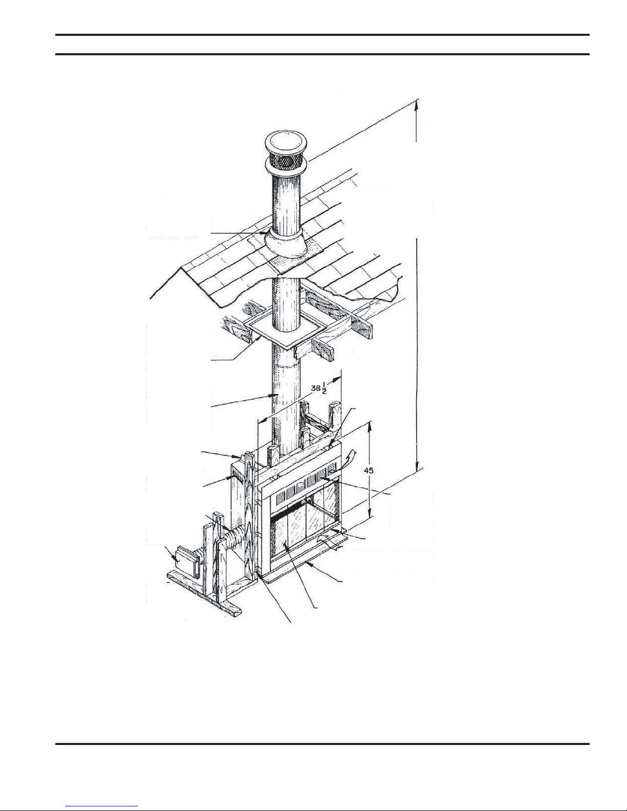
FIREPLACE FEATURES
Figure 1
Residential Installation
Roof Flashing
Model 1212 or 612
Firestop Model SF
(requires 14¹⁄₂” x 14¹⁄₂”
Opening)
(1³⁄₄” Min. Air Space to
Combustibles)
Chimney 2” Min. Air space
Clearance to Combustibles
Chimney Section S12 (1 ft. pipe)
S18 (18” pipe)
S36 (3 ft. pipe)
S48 (4 ft. pipe)
Top Spacer
Model SC
Chimney Cap
B36LA & B36RA Woodburning Fireplaces
13 ft. = Min. Height (No offsets)
13 ft. = Min. Height (2 30° Elbows)
21 ft. = Min. Height (4 30° Elbows)
86 ft. = Max. Height (Chimney support
every 30 ft.)
See NOTE
Fireplace Model
B36RA
53D9041
Zero Clearance to
Combustibles at
Side Spacers
Flexible Duct
Type FP-4-U
Combustion Air
Assembly
Model OAC4
FP2157
Cool Air Inlet (See Caution)
CAUTION: Do not block air inlets
or outlets
Galvanized Sheet Metal - 6 x 42
(Front & 6 x 23 (end)
Glass Doors - Model WB36LR
Nail to Framing Members
(Floor Line)
Warm Air Outlet (See Caution) Model C36RA Shown B
Model has no louvers in top
panel
NOTE: Combustible materials should not be installed below top spacer. Noncombustible materials
such as brick or tile may be used to trim face of the fireplace but should not cover any portion of the
louvered panel or cool air inlet.
Combustibles must not overlap the black painted face of the fireplace.
5
Page 6
B36LA & B36RA Woodburning Fireplaces
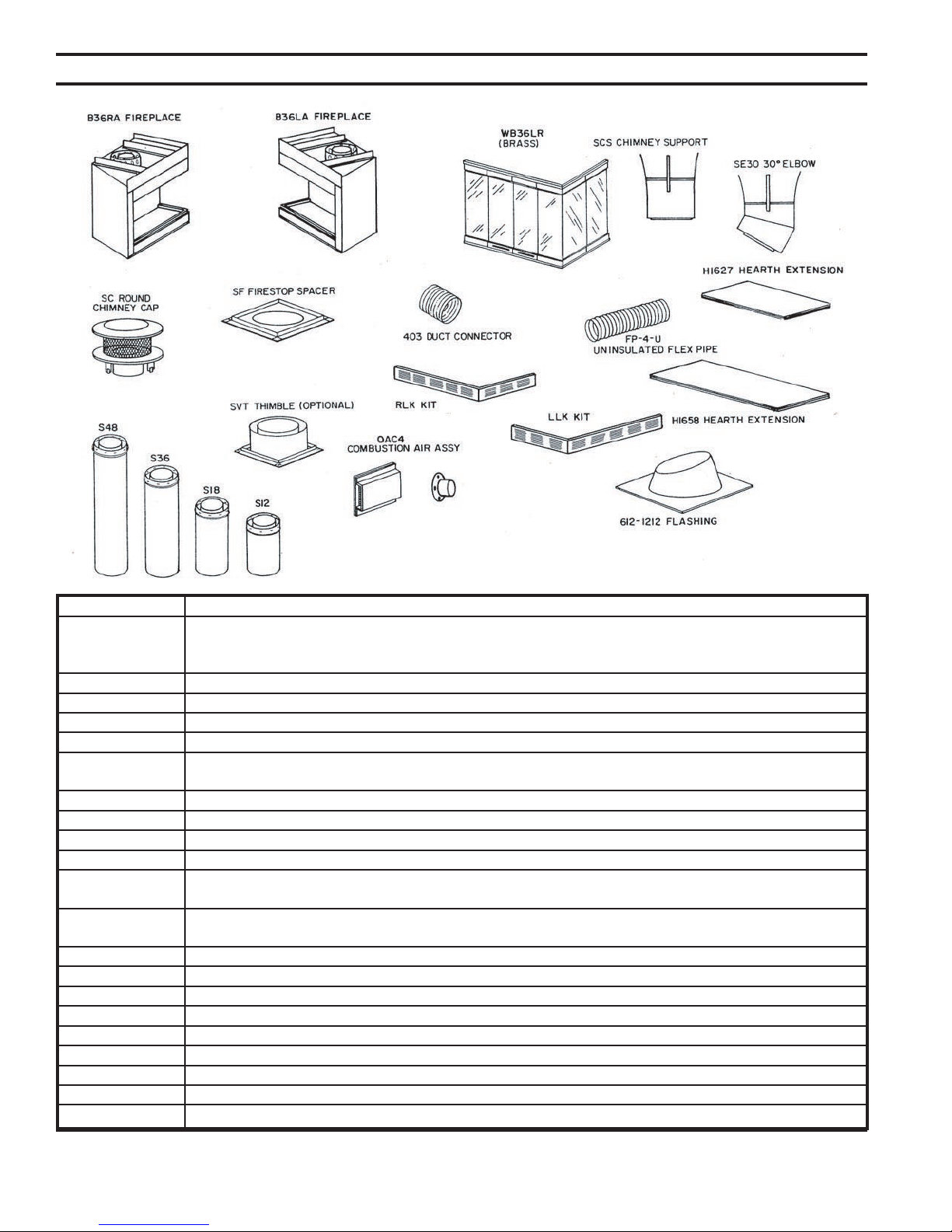
FIREPLACE COMPONENTS
Model Number Description
B36LA, B36RA Left or right end open fireplace. Includes wire firescreen, sealing flue damper and outside com bustion air capability. When installed, outside combustion air can be connected to left side. Refer
to installation instructions for details.
S48 4-foot chimney section (8-inch diameter flue)
S36 3-foot chimney section (8-inch diameter flue)
S18 11/2-foot chimney section (8-inch diameter flue)
S12 1-foot chimney section (8-inch diameter flue)
SE30 30° elbows (package contains two 8-inch diameter elbows). One pair is required for each offset.
Maximum - two pairs (4 elbows) per chimney.
SCS Chimney support (required when chimney height exceeds 30 feet)
SC Round chimney cap for contemporary installations. Includes storm collar.
SCL Round telescoping chimney cap
SQL8 Square telescoping chimney cap
612 0-6/12 pitch flashing for contemporary installation. One required with SC round chimney cap on
0-6/12 pitch roof
1212 6/12 - 12/12 pitch flashing for contemporary installation. One required with SC round chimney
cap on 6/12 - 12/12 pitch roof
SF 141/2” firestop spacer - One required at each ceiling or floor level
SF-30 Firestop spacer - for 30° chimney incline through ceiling or floor
FP-4-U 4-inch insulated combustion air duct - 8 foot lengths
403 4-inch duct connector (for splicing FP-4 ducts). Includes two clamps
OAC4 4-inch outside combustion assembly
WB36LR Optional polished brass glass door kit
H1658 Hearth extension board for front opening (16” x 58”)
H1627 Hearth extension board for end opening (16” x 27”)
S8 Telescoping assembly for use with telescoping chimney caps
6
53D9041
Page 7
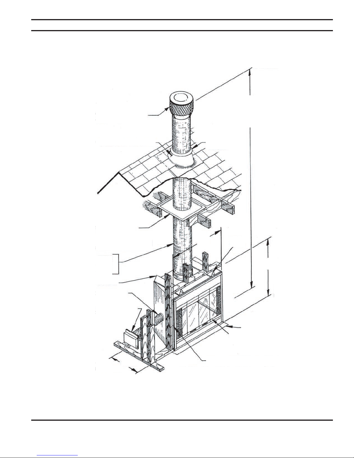
FIREPLACE FEATURES
Figure 2 - Residential Installation -
Using “E” Series Triple Wall Thermosyphoning Chimney Components
Model LF-CC-1 or LF-CCL-1
Round Termination Cap
B36LA & B36RA Woodburning Fireplaces
Flue Outlet Height
14 ft. = Min. Height (No offsets)
14 ft. = Min. Height (2 30° Elbows)
21 ft. = Min. Height (4 30° Elbows)
86 ft. = Max. Height (Chimney support
every 30 ft.)
Roof Flashing Model 612
Firestop Model LF-FS-2
(requires 17” x 17” Opening)
Chimney 2” Min. Air space
Clearance to Combustibles
Chimney Section E12 (1 ft. pipe)
E18 (18” pipe)
E36 (3 ft. pipe)
E48 (4 ft. pipe)
Top Spacer
Flexible Duct
Type FP-4-U
Combustion Air Assembly
Model OAC4
Storm Collar
38¹⁄₂”
See NOTE
37⁵⁄₈”
Bottom of Fireplace
FP2159
NOTE: Combustible materials should not be installed below top spacer. Noncombustible materials
such as brick or tile may be used to trim face of the fireplace but should not cover any portion of the
louvered panel or cool air inlet.
Combustibles must not overlap the black painted face of the fireplace.
53D9041
22¹⁄₂”
Galvanized Metal Strip
Glass Doors - Model WB36LR
Nail to Framing Members
CAUTION: Do not block
air inlets or outlets
7
Page 8
B36LA & B36RA Woodburning Fireplaces
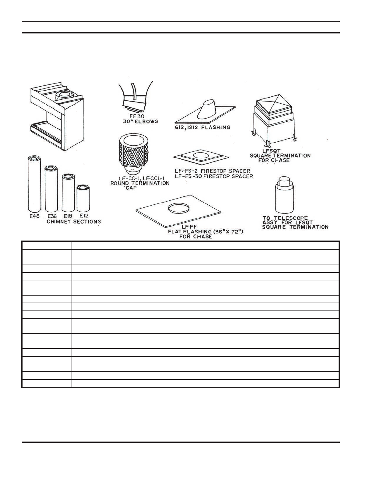
“E” CHIMNEY COMPONENTS
1. When installing “E” series triple wall chimney system on the B36LA and B36LR, do not mix chimney
system components other than those listed below.
2. Maintain 2” airspace clearance to combustibles.
3. Use same offset and rise chart for chimney when installing elbows.
Model Number Description
E48 4-foot chimney section (8-inch diameter flue)
E36 3-foot chimney section (8-inch diameter flue)
1
E18 1
/2-foot chimney section (8-inch diameter flue)
E12 1-foot chimney section (8-inch diameter flue)
EE30 30° elbows (package contains two 8-inch diameter elbows). One pair is required for each offset.
Maximum - two pairs (4 elbows) per chimney.
ECS Chimney support (required when chimney height exceeds 30 feet)
LFCC-1 Round chimney cap for contemporary installations. Includes storm collar.
LFCCL-1 Round termination cap for chase installation (includes inlet air telescope)
612 0-6/12 pitch flashing for contemporary installation. One required with SC round chimney cap on
0-6/12 pitch roof
1212 6/12 - 12/12 pitch flashing for contemporary installation. One required with SC round chimney
cap on 6/12 - 12/12 pitch roof
LF-FS-2 17” firestop spacer - One required at each ceiling or floor level below 20 foot chimney height
LF-FS-30 Firestop spacer - for 30° chimney incline through ceiling or floor
LFSQT Square termination for chase installation. Model T8 telescope assembly requried but not included
T8 Telescoping assembly for use with telescoping chimney caps
LF-FF Flat flashing for chase installation (36” x 72”)
8
53D9041
Page 9
FIREPLACE LOCATION
32”
10”
23”
38
”
42”
8”
22
”
5”
3/4”
34”
30
”
45”
23”
22”
34
”
22”
B36LA & B36RA Woodburning Fireplaces
CAUTION: Do not install fireplace over carpeting.
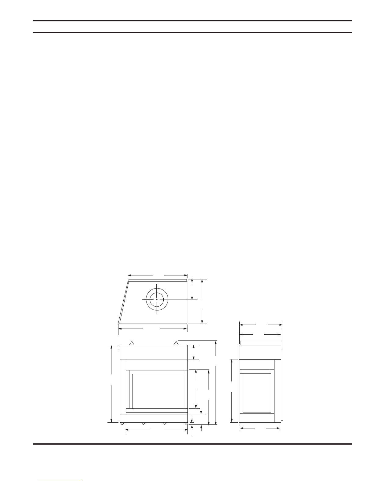
This fireplace does not require any special foundation. If the fireplace is to be trimmed with large stone or
brick facing, an adequate foundation is required to support these materials. Use Figures 5 and 6 as a guide
for selecting a location and determining the space required for the fireplace.
The location for the fireplace should be adjacent to the load bearing wall and away from objects that will
create drafts that could disturb the normal flow of air into the fire. Such objects are frequently opened doors
and central heat and air outlets and returns. Figure 4 illustrates various types of locations and installation
and Figure 1 gives additional information concerning installation heights, construction details, and methods
on installation.
A location that requires cutting the least number of joists and rafters for the chimney installation will simplify
and reduce installation cost. The opening required for passage of the chimney through the roof, ceilings and
floors must be 17 inches square as indicated by Figures 6, 7 and 8. The 17 inch square opening provides
for the installation of the model LF-FS-2 firestop spacer in a residential installation.
Since the pitch of the roof influences the opening size required at the roof level, table 1 should be used as
a guide for sizing the roof opening.
Proper selection of a chimney outlet location is also important. Objects such as overhanging or nearby
trees, adjacent building or embarkments or unusual roof designs can all create air turbulence and interfere
with chimney performance and cause the fireplace to spill smoke into the room.
A factory-built fireplace, properly installed in a single story wing of a multi-story building as shown in Figure
9, may be affected by environmental factors that will cause poor chimney draft and occasional spillage of
smoke from the fireplace opening. Although this occurs infrequently, location of the fireplace in the preferred
location as indicated by Figure 9 is recommended.
If the chimney is to pass through living areas or spaces used for storage, be sure that it will be possible to
enclose the chimney to prevent contact with and possible damage to the chimney. Elbows may be used to
avoid obstructions such as electrical wires, water, or sewer pipes, attic fans, heating ducts, etc. Refer to the
section of this manual concerning chimney offsets for proper elbow installation and use.
If the failure is to be installed in an outside wall, the surrounding walls should be enclosed and insulated.
Failure to properly enclose the fireplace will cause a heat loss and diminish the fireplace efficiency due to
transfer of heat through the fireplace to the outside.
Figure 3
53D9041
9
Page 10

B36LA & B36RA Woodburning Fireplaces
All fireplaces installed over a combustible floor must incorporate a noncombustible earth extension. It is
required to protect the floor in front of the fireplace from both radiant heat and sparks.
Hearth extension dimensions should be determined by using the chart below. Use hearth extensions as illustrated in Figures 5, 10 and 11 or use an acceptable thickness of a durable noncombustible material with
an equal or greater insulating value than K - .43 BTU in/ft2-HR-F°, or a thermal resistance that equals or
exceeds R = 1.16. These materials should be covered with a decorative noncombustible veneer.
NOTE: Any noncombustible material with a K factor value that is less than .43, or whose R value is more
than 1.16 or 1/2” thick material is acceptable.
HOW TO DETERMINE HEARTH EXTENSION REQUIREMENTS
The following information is provided to determine required thickness for any noncombustible material when
either the K or R values are known. They are expressed as the following: K = BTU-in/ft2-HR-F° or R = HRF°/BTU. These materials should be covered by a decorative noncombustible material such as tile, brick,
stone or slate. To determine the thickness needed for a material other than those listed in the chart, use the
following formulas to calculate that which will be an acceptable equivalent.
The ability of insulating material to retard the transfer of heat may be expressed as either Thermal Conductance (C), Thermal Conductivity (K) or Thermal Resistance (R). The mathematical relationship of these
values and the formulas for converting one value to another is as follows:
C = K divided by the material thickness
(Example: C = .43 divided by 1/2 (.50) C = .86)
K = C multiplied by the material thickness
(Example: K = .86 multiplied by 1/2 (.50) K = .43)
R = The material thickness divided by K
(Example: R = 1/2 (.50) divided by .43 R = 1.16)
With either type hearth extension minor shifting of the supporting floor or expansion and contraction may
eventually cause a crack to develop between the hearth extension and the face of the fireplace. To help
prevent the crack from developing, the hearth extension materials must be firmly fastened in place. Wall
ties should be screwed to the face of the fireplace and imbedded n the mortar joints of brick, stone or other
noncombustible materials. The metal safety strip packed with the fireplace must be placed beneath the fireplace and extended under the hearth extension or into a mortar joint of the hearth extension. In the event
a crack does eventually develop, the metal safety strip will serve as a barrier to prevent sparks or embers
from falling from the fireplace onto combustible flooring materials.
*Refer to Figure 5 for an alternate hearth extension using brick only.
WARNING: The space between the hearth extension and fireplace must be sealed with a noncombustible material. When installing the hearth extension, be careful not to block the heat circulating
air inlets (louvers, slots, etc.) Figure 5
FLOOR PROTECTION
Wall Protection
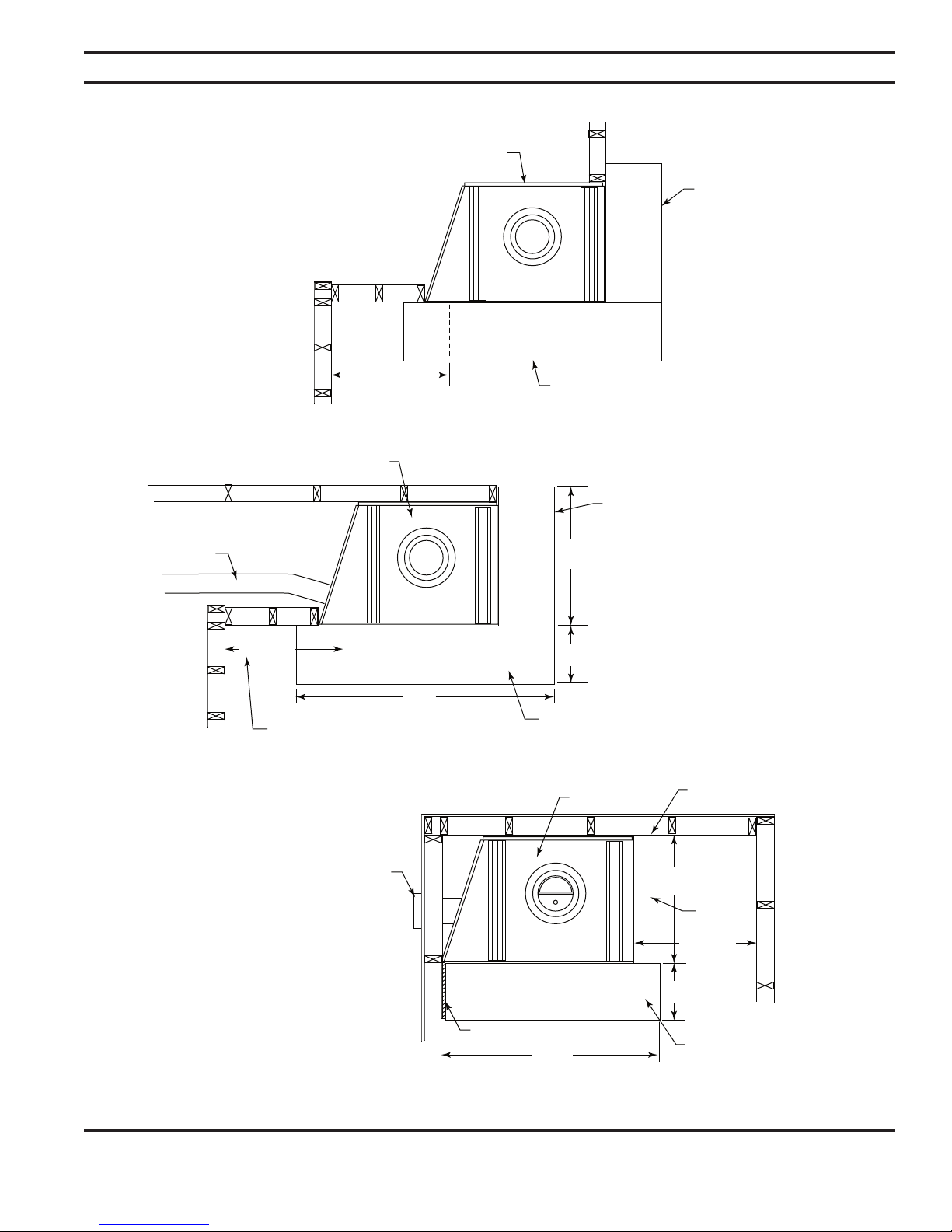
A model WS wall shield or an equivalent must be installed when the closed end of the fireplace is closer
than 24” from a wall perpendicular to the face of the fireplace. Figures 10 and 11. The WS wall shield should
be attached securely to the wall by driving nails or screws through it into the wall studs. The wall shield
should be covered by a decorative noncombustible material such as brick, tile, slate, etc.
The WS wall shield is constructed of 1” of Micore CV230 insulation board, manufactured by U.S. Gypsum
Corporation, covered by a sheet of galvanized metal. An alternate insulating material with a K factor of .43
or lower can be used. Refer to the preceding section for instructions for selecting an alternate insulating
material. WARNING: If not installed, operated and maintained in accordance with the manufacturer’s
instructions, this product could expose you to substances in fuel or from fuel combustion which
can cause death or serious illness and which are known to the State of California to cause cancer,
birth defects or other reproductive harm. Also, operation, installation and servicing of this product
could expose you to airborne particles of glass wool fibers known to the State of California to cause
cancer through inhalation.
10
53D9041
Page 11
CLEARANCES
54”
23”
46” Min.
16”
24” Min.
58”
16”
27”
24” Min.
Figure 4
B36LA & B36RA Woodburning Fireplaces
C36RA or
B36RA
Hearth Extension
Model I627
Outside Air
Clearance from Fireplace
Opening to Sidewall When
Wall Shield IS NOT Used
C36RA or B36RA
Minimum Clearance from
Fireplace Opening to
Sidewall When Wall shield
IS NOT used
Hearth Extension
Model I658
Hearth Extension
Model I627
Hearth Extension
Model I658
Model C36RA
or B36Ra
Shield Not Required
on This Wall
53D9041
Outside Air
Wall Shield Model WS
Hearth
Extension
Model I623
FP2161
Hearth Extension
Model I654
11
Page 12
B36LA & B36RA Woodburning Fireplaces
39”
6” Min.
Figure 5
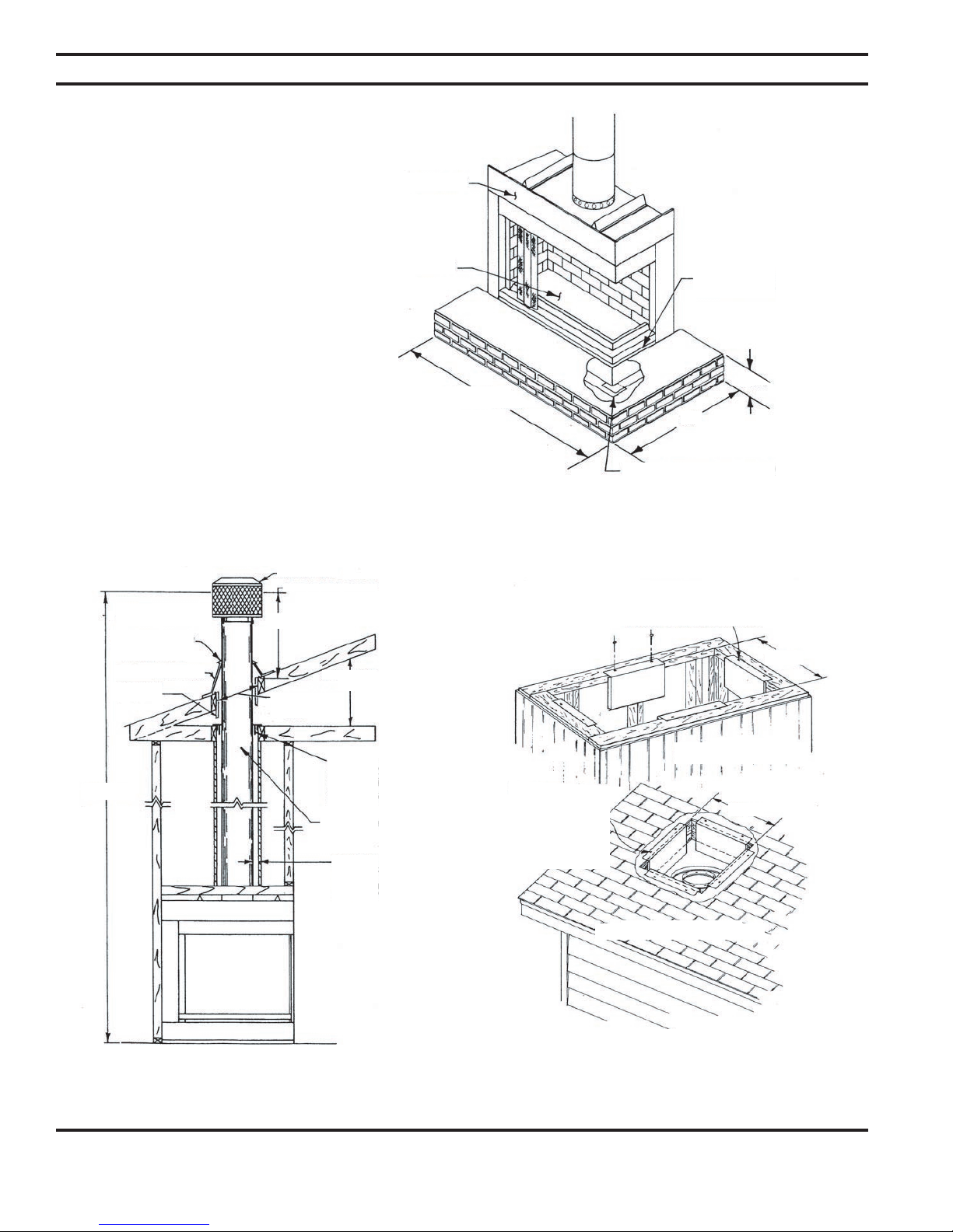
Alternate Brick or Stone Hearth
Extensions for use with the B36LA,
B36RA, C36LA & C36RA Fireplace
FIREPLACE INSTALLATION
Fireplace
Figure 6
Storm Collar
(Included with
Chimney Cap)
Roof Joist
Shields
Single Story Installation
with Attic Space
Flashing (612
or 1212)
Chimney Cap
3’ Min.
Refer to Table
1 for Roof
Opening Size
Attic Space
Hearth
58” or 54” if Wall
Shield is Used
Figure 7
Do Not Block Air
Inlet Openings
FP2162
Safety Strip Required
When Unit is Placed on
Combustible Floor or
Pratform
Installation of Shields with MHSC End Open Fireplace
and “S” Series Chimney
Roof Joists Shields - Secure to Top of Chase Top
Opening Before the Chase Top Flashing is Installed
14¹⁄₂” Min.
12
13’ Min.
FS Firestop Spacer 14¹⁄₂”
x 14¹⁄₂” Framed Opening
1³⁄₄” Clearance to Combustibles with FS Firestop
“S” Series Chimney
2” Min. Air Space
Clearance Between
Combsutibles and
Chimney
FP2163
Secure Shields to
the Roof as shown
Before Installing the
Roof flashing on a
Conventional Roof
Conventional Roof Installation
Chase Top Installation
14¹⁄₂” Min.
FP2164
53D9041
Page 13
FIREPLACE INSTALLATION
B36LA & B36RA Woodburning Fireplaces
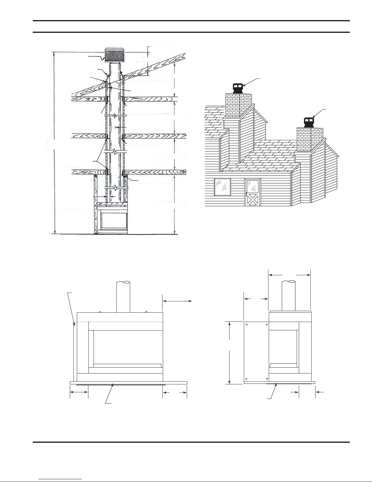
Figure 8
Chimney
Cap
Flashing (612
or 1212)
14¹⁄₂” Square Hole in
Joist 1³⁄₄” MCearance to Combustibles When Using
FS Firestop
Max. Installation
Height 86’
14¹⁄₂” Square
Hoel in Joist
2” Min. Air
Space Clearance Between
Chimney and
combustibles
Storm Collar
Flue Outlet Height
3’ Min.
Refer to Table 1 for
Roof Opening Sizes
Roof Joist Shields
Firestop Spacer
Installed Above
Joist in Attic
Space
“S” Series Chimney
Firestop Spacer
Firestop
Spacer
Third Floor Area
Second Floor Area
First Floor Area
Attic Space
Figure 9
Preferred
Location
Poor
Location
FP1882
Figure 10
4” Min. when
Wall shield is
Used
Wall Shield
When Perpendicular Wall is
Less Than 24”
from Opening
FP1883
Models H1658 or
Equivalent Hearth
Extensions
48” Clearance from
Perendicular Wall
16”
16”
Model
36”
Models H1627 or
Equivalent Hearth
Extensions
WS
Wall
Shield
23”
FP2165
8”
53D9041
13
Page 14
B36LA & B36RA Woodburning Fireplaces
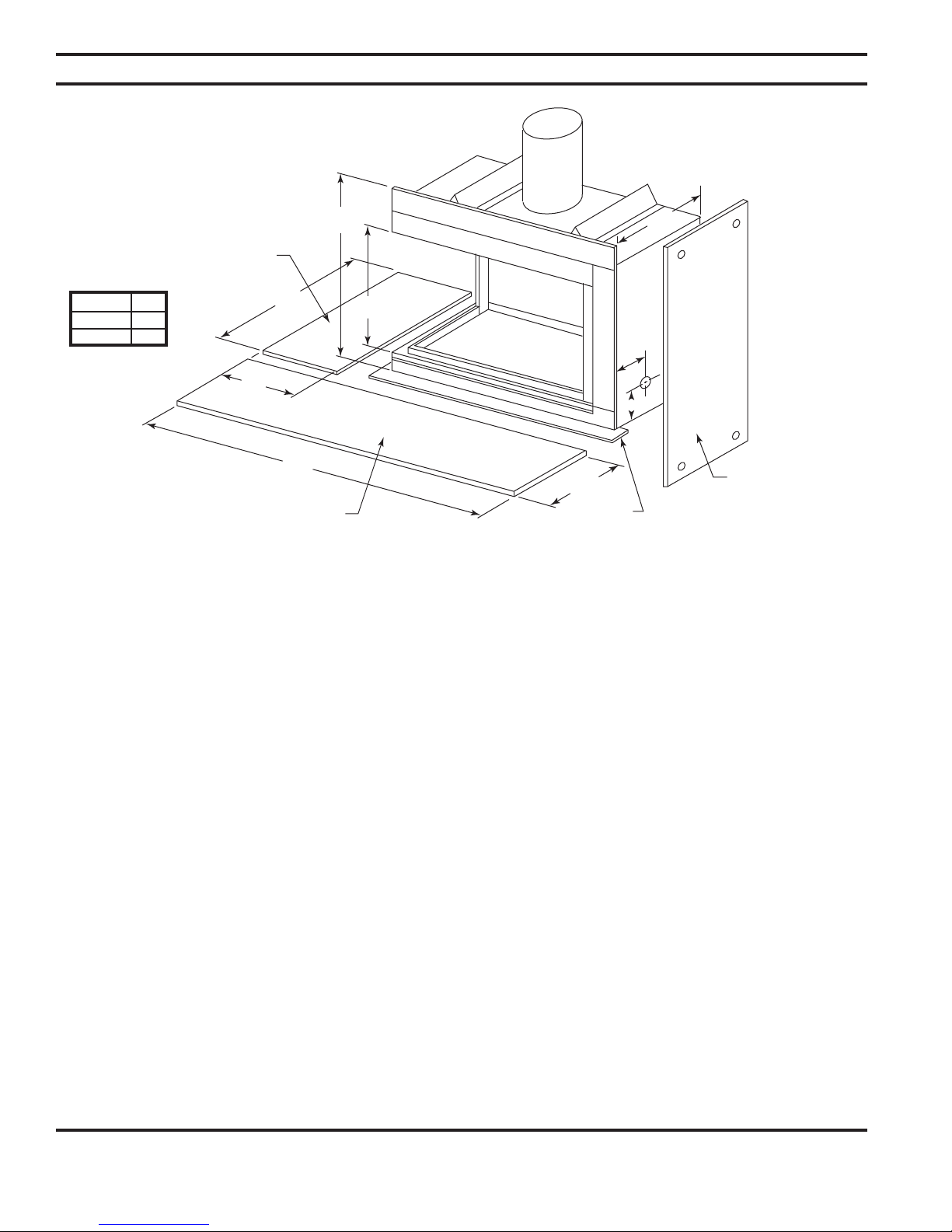
“X”
“X”
42
”
22
”
16”
16”
8”
9”
23”
Figure 11
Hearth Extension Model
H1627 or Equivalent
Model “X”
H1627 27”
H1658 58”
Hearth Extension Models
H1656 or Equivalent
FIREPLACE INSTALLATION
FP2166
Wall Shield Model WS
or Equivalent When
Fireplace
Safety Strip on two
(2) Sides
Side Wall Clearance
is Less Than 24”
Location Selection
Unpack and check the fireplace and chimney for damage. If any items have been damaged, report this to
your dealer. Before beginning the installation, be sure you have the proper parts in sufficient quantity. Refer
to the Parts Diagram and List section of this manual for proper identification of parts.
Do not substitute parts. Use only parts listed for use with Model B36LA and B36RA fireplaces.
Fireplace Installation
1. Refer to Figure 1 for examples of typical fireplace framing.
2. Be sure the location of the fireplace will provide the required safety clearances as specified by this instruction manual.
3. Set the fireplace in the desired location and be sure it is securely supported and leveled. Install metal
safety strip for hearth extension as shown by Figures 10, 11 and 12. Check the face of the fireplace with
a carpenter’s level to make sure the fireplace is plumb. If it is not plumb, plumb it by placing shims under
the edges of the fireplace.
4. Block in the fireplace to prevent any shifting of the firebox. Secure the fireplace with nails or screws
through the flanges located on each side of the fireplace. Install chimney and other fireplace compo
nents as needed.
NOTE: Some local codes may require electrically grounding the fireplace and chimney.
Chimney Installation
In order to assure safe and satisfactory performance of the fireplace, it is very important to properly install
the chimney. This is an important part of the installation and the sections of this manual pertaining to chimney installation should be reviewed very thoroughly.
For your safety, some of the important things to remember in regard to chimneys are listed below:
1. Use only parts and accessories labeled for use with this fireplace.
2. Use only undamaged parts and accessories.
-
14
53D9041
Page 15
MOBILE HOME INSTALLATION
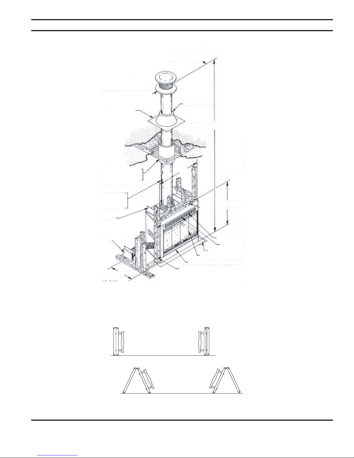
38”
45
”
11’9” Min. Height
22” Min.
Mobile Home Installation
B36LA & B36RA Woodburning Fireplaces
Figure 12
Round Chimney
Cap Mdel SC
Roof Flashing Model
612
Firestop Thimble Model SVT
(Thimble extensions when
needed Mdels SVTE)
14¹⁄₂” x 14¹⁄₂” Framed Opening
Chimney 2” Min. Air Space
to Combustibles
S12 1 ft. pipe
S18 1¹⁄₂ ft. pipe
S36 3 ft. pipe
S48 4 ft. pipe
Top Spacer
Flue Outlet Height
Storm Collar
NOTE: Combustible material
should not be installed below top
spacer. Noncombustible materi
als such as brick or tile may be
used to trim face of the fireplace
but should not cover any portion
of the louvered panels. Combustibles must not overlap the black
painted face of the fireplace.
Bottom of Fireplace
-
Combustion Air
Kit Model OAC6
Front to Back
Framing Dimension
Figure 13
Warm Air Inlet
RLK Louver Kit
(Use LLK on Left End Open Fireplace)
Galvanized Metal Strip
WB36LR Glass Door
Cool Air Inlet
Nail to Framing
Members
Fireplace - Model C36RMA (B36RA with
RLK Louver kit, WB36LR Glass Door, and
OAC6 Combustion Air)
Model C36LMA (not shown) same as
above, except uses LLK Louver Kit on the
B36LA fireplace
Correct position for doors when open
FP2176
Partially open doors
WARNING: Operating doors in this position is incorrect.
53D9041
15
Page 16
B36LA & B36RA Woodburning Fireplaces
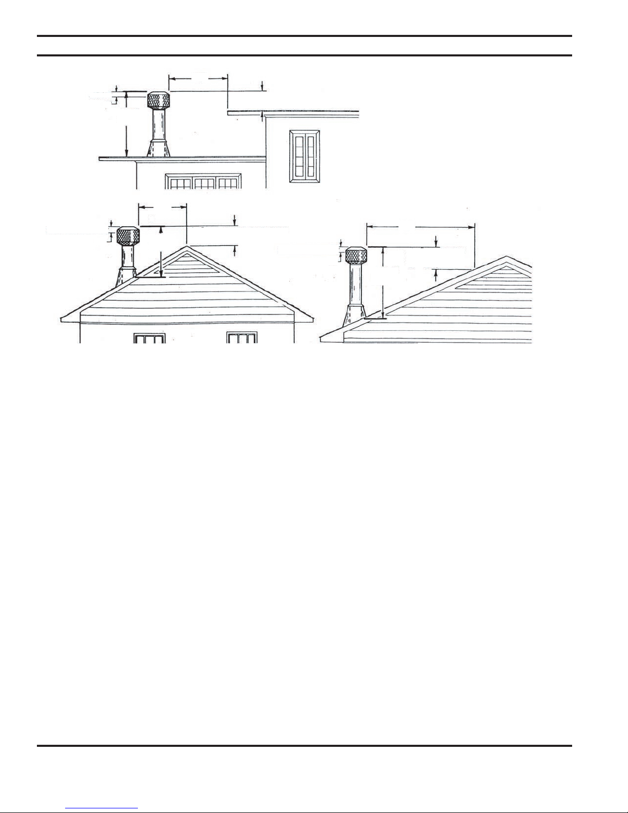
3’7” Min.
7”
“A”
2’7” Min. when
Dimension “A” is 10’ or Less
2’7” Min. when
Dimension “A” is
10’ or Less
2’7” Min. when
Dimension “A” is 10’
or Less
“A”
“A”
Flue Outlet
Height
Flue Outlet
Height
Flue Outlet
Height
7”
7”
3’7” Min.
3’7” Min.
CHIMNEY INSTALLATION
Figure 14
NOTE: Flue outlet should be 2’ above all
portions of the building within 10’. The
chimney must not extend more than 90”
above the roof without additional support.
3. Enclose the chimney where it passes through the living spaces to prevent contact with and possible dam-age to the
chimney.
4. Install firestop spacers at each ceiling level.
5. Install the proper chimney cap or chimney housing on the chimney to prevent the entry of rain and debris into the
chimney and to assure the proper venting of smoke.
6. Do not use more than four elbows in the chimney.
NOTE: To select the proper chimney height, refer to Figure 1. The flue outlet must be a minimum of three feet above
the highest point where the chimney penetrates the roof and a minimum of two feet above all portions of the building
within ten feet. If the chimney is to include elbows to offset the chimney, refer to the Chimney Offset and Cap Installation
section of this manual. There must be at least two inches air space between all sections of the chimney and combustible materials between floors.
1. Lay out, cut and frame openings through all ceilings and the roof at the point where the chimney will pass through.
Unless the chimney is to be offset, the point where the center line of the chimney will pass through the ceiling and
roof can be determined with a plumb line as shown by Figure 15. The fireplace should be located in the planned
installation position. After the center line is established and a nail is driven to mark the point, the opening can be
cut if you are satisfied with the chimney location relative to ceiling and roof joists and/or any other obstructions. The
roof opening center line should be marked by driving a nail through the roof from underneath that will penetrate the
roof and can be located from the rooftop. If the chimney is to penetrate a pitched roof, the hole in the roof must be
rectangular instead of square and should be sized according to Table1.
2. Install the firestop spacer as required from beneath the ceiling unless the space above is attic space. In an attic, the
firestop spacer should be installed at the floor level of the attic. You must have joists or headers on all four sides of
the spacer and use a minimum of four 8-penney nails to secure the spacer.
3. To install the “S” series chimney sections, insert the male end of the flue, the smallest diameter pipe, into the flue
outlet of the fireplace and press down until the snap locks engage. Continue the process, adding the chimney sec
tions on top of each other until the chimney is at least six inches above the roof opening on all sided. As the chimney
sections are installed, check each joint to make sure it is properly locked to the previous section. If additional strength
of the outer pipe joints is desired, you may use two or three sheet metal screws placed through the area where the
outer pipes overlap one another. To install these screws, drill a 1/8-inch diameter hole through the chimney sections,
taking care not to penetrate the inner flue pipe. WARNING: Be very careful when drilling the holes into the outer
pipe. The drill must not penetrate the inner stainless steel pipe.
16
53D9041
-
Page 17
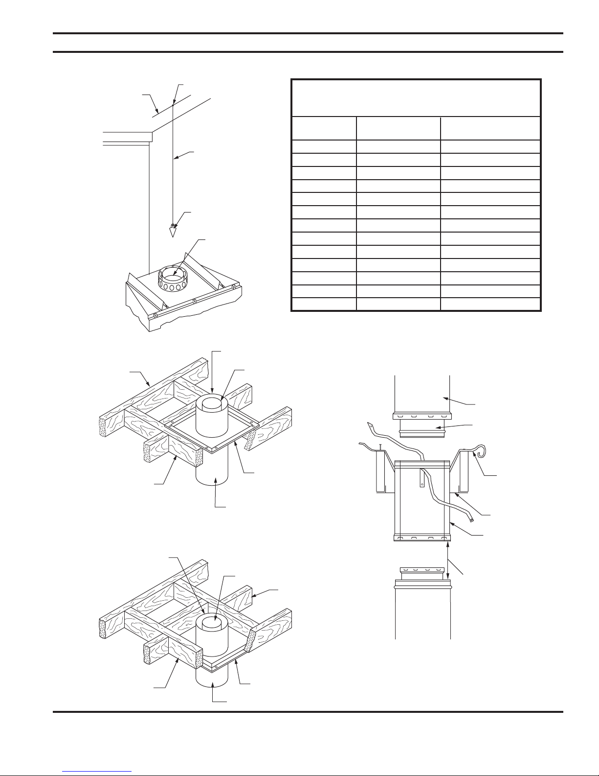
CHIMNEY INSTALLATION
Figure 15
Centerline of
Chimney
Actual Center Point
Plumb Line
Plumb Bob
Imaginary Center
Point
FP1891
B36LA & B36RA Woodburning Fireplaces
Table 1
Minimum Required Roof Opening
Minimum Framed Opening
“S” Series “E” Series
Roof Pitch Double Wall Triple Wall Chimney
0/12 14
1/12 14
2/12 14
3/12 14
4/12 14
5/12 14
6/12 14
7/12 14
8/12 14
9/12 14
10/12 14
11/12 14
12/12 14
¹⁄₂” x 14¹⁄₂” 17” x 17”
¹⁄₂” x 14⁵⁄₈” 17” x 17¹⁄₈”
¹⁄₂” x 14³⁄₄” 17” x 17¹⁄₄”
¹⁄₂” x 15” 17” x 17¹⁄₂”
¹⁄₂” x 15¹⁄₄” 17” x 17³⁄₄”
¹⁄₂” x 15³⁄₄” 17” x 18¹⁄₄”
¹⁄₂” z 16¹⁄₄” 17” x 18³⁄₄”
¹⁄₂” x 16⁷⁄₈” 17” x 19³⁄₈”
¹⁄₂”x 17¹⁄₂” 17” x 20”
¹⁄₂” x 18¹⁄₈” 17” x 20⁵⁄₈”
¹⁄₂” x 18⁷⁄₈” 17” x 21³⁄₈”
¹⁄₂” x 19³⁄₄” 17” x 22¹⁄₄”
¹⁄₂” x 20¹⁄₂” 17” x 23”
Figure 16
Firestop Spacer Installation at Attic Level
Ceiling Joist
Firestop Spacer Installation at Floor Levels
Header
Inlet Air Pipe
Inlet Air Pipe
Flue Pipe
Firestop Spacer
Chimney Section
Flue Pipe
Floor
Joist
Figure 17
Outer Pipe
Flue
Support Straps
Fasten Securely
Firestop
Chimney Support
Snap Lock Chimney
Support Securely to
Lower pipes Before
Fastening Support
Straps
Header
53D9041
FP1890
FP1892
Firestop Spacer
Chimney Section
17
Page 18

B36LA & B36RA Woodburning Fireplaces
NOTE: If you intend to have a total fireplace installation of more that 30 feet you must use a chimney support at or
below 30 feet to support the weight of additional chimney pipe. If it is impossible to nail the chimney support to the
load bearing framing of the building at the 30 foot level, the chimney support may be installed at a lower level if the
height of the chimney above the support does not exceed 30 feet. Effective height of the chimney support is 16³⁄₄”.
Chimney supports must be installed at 30 foot intervals.
To install the chimney support, place the crimped end of the flue and outlet air duct portions into the last section of
chimney pipe. Push down until the outside or inlet air duct of the chimney support overlaps and snap locks the chimney support into the chimney section.
Nail the support straps tightly to a building frame member or ceiling joist as shown by Figure 18. You must use at
least two 8-penney nails per strap.
CHIMNEY OFFSET INSTALLATION
Elbow Installation
NOTE: If triple wall elbow is to be placed directly to the top of the fireplace, it will be necessary to bend a tab located
on each of the four (4) inlet air collar brackets. Bend these tabs over only when using a triple wall elbow to start a
chimney run. The tabs may be easily bent with your fingers or pliers. Figure 19
The following are important points that should be observed when installing elbows on the fireplace:
1. The support straps of all elbows not installed directly on top of the fireplace should be nailed securely to the sur
rounding structure. This allows the support strap to carry the weight of the chimney above the elbow and prevents
this weight from breaking the elbow or chimney sections apart. Figure 18
2. Elbows should not be used in any combination that inclines the chimney more than 30 degrees from vertical.
3. The limitations on the quantity of elbows per chimney are as follows: If the total height of the fireplace and chim
ney is—16’0” or more — two elbows may be used in the chimney. 21’ - 0” or more — four elbows may be used
in the chimney.
4. The inclined portions of chimneys that pass through living spaces likely to be used for storage should be enclosed
to avoid contact with and possible damage to the chimney. The minimum air space of two inches between the
chimney and enclosing materials must be maintained. Figures 20 and 21 illustrate elbow installations.
5. The length of the inclined portion of chimney between elbows must not exceed 6 feet when unsupported or 20
feet if the chimney is supported at six-foot intervals with support such as metal support straps.
6. When enclosing the elbows and inclined portions of the chimney, enclosing materials must be installed vertically
to maintain the required two-inch minimum air space clearance to the chimney at the extremities of the offset. It
is recommended that enclosing material not follow the inclined portions of the chimney.
-
-
Offset Installation Sequence
1. Determine the location and amount of offset required, then select the combinations of chimney sections and elbows required from the offset chart. Refer to Page 19.
2. Install the first LE30 elbow by placing the extended flue into the mating part of the fireplace or chimney section.
Push down until the outside or inlet air duct of the elbow overlaps and the snaps lock the elbow into the fireplace
or chimney section.
3. Nail the support straps to the framing member with a minimum of two 8-penny nails per strap.
4. Install the sections of pipe between elbows until the proper number of chimney sections have been installed.
5. Install the second elbow to return the run of the chimney to vertical.
6. Nail the support straps of the second elbow to a building frame member.
7. Continue installing the vertical portion of the chimney.
NOTE: If the inclined portion of the chimney passes through a floor or ceiling, an SF30 firestop spacer should be
installed to provide the firestop and support required. Be sure proper spacing in maintained between the chimney
and combustibles. Figure 22
18
53D9041
Page 19
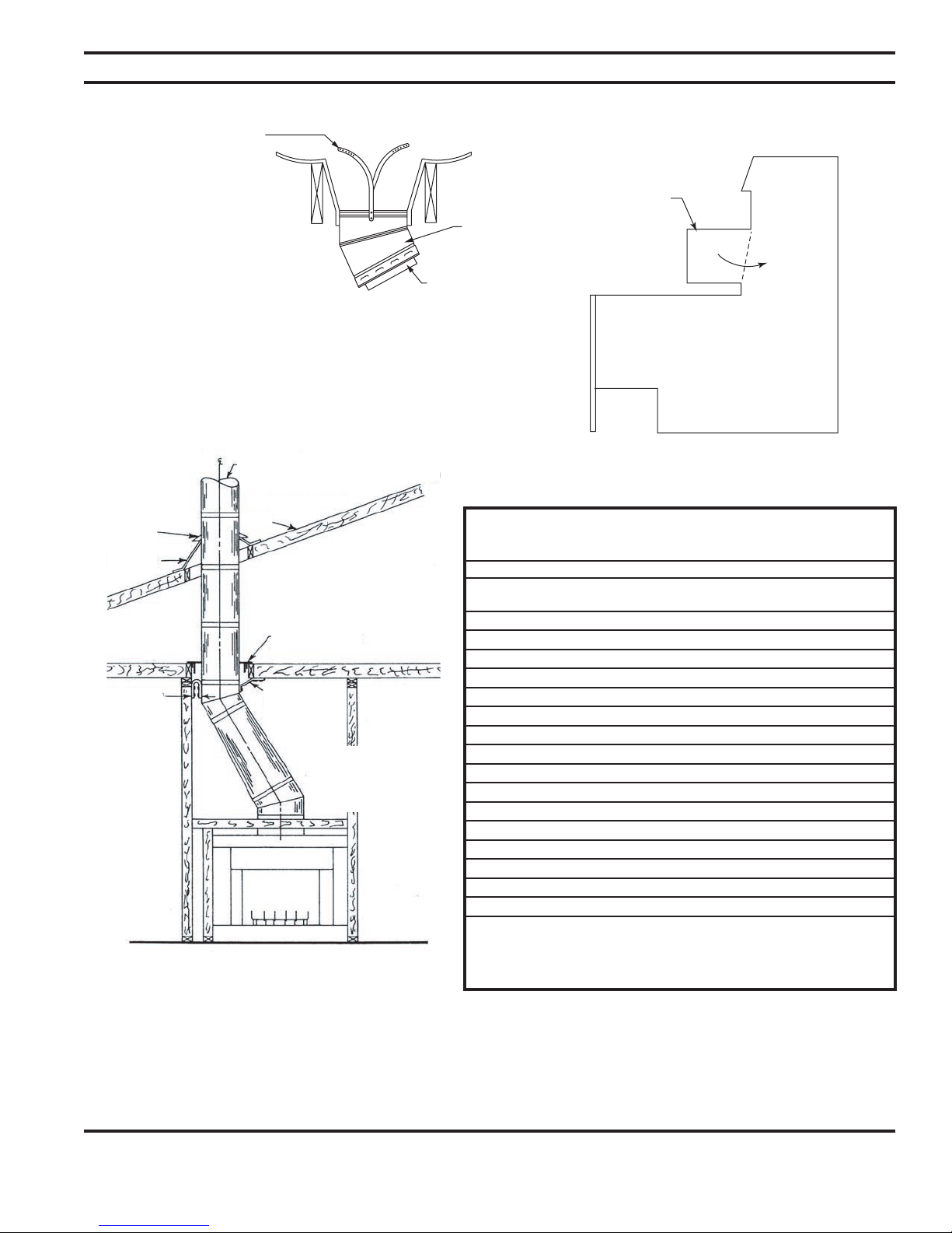
CHIMNEY OFFSET AND CAP INSTALLATION
Figure 18
B36LA & B36RA Woodburning Fireplaces
All four (4) support straps
must be nailed on to framing member around the
elbow with a minimum of
two (2) 8-Penny nails per
strap
Figure 20
Storm Collar
Flashing
2” Minimum
Air Space
Clearance to
Combustibles
with use of FS
Firestop
Continue chimney to proper
height and install round chmney
cap or chimney housing
Roof
Firestop Spacer as
Required
Fasten
Suport Straps
Securely
NOTE: Two (2) elbows
may be used when
total installation height
exceeds 13’8”
FP2169
Figure 19
For Triple Wall
Elbows, Bench
Inlet Air
Pipe
Flue
tab Over
Collar Bracket
FP2168
Table 2
Select desired offset and read across Table to obtain rise, quan
tity of chimney sections and elbows
30° Elbow
1ft. 1¹⁄₂ ft. 3 ft. 4 ft. Elbows
Offset Rise Sections Sections Sections Sections Req’d
9
³⁄₈” 25⁵⁄₁₆” 1 -- -- -- 1 pr.
³⁄₈” 30¹⁄₂” -- 1 -- -- 1 pr.
12
17³⁄₄” 39¹³⁄₁₆” 1 1 -- -- 1 pr.
³⁄₄” 45” -- 2 -- -- 1 pr.
20
23
¹⁄₈” 49¹⁄₈” 2 1 -- -- 1 pr.
26³⁄₄” 55³⁄₈” 1 -- 1 -- 1 pr.
³⁄₄” 65¹³⁄₁₆” 1 -- -- 1 1 pr.
32
35
³⁄₄” 71” -- 1 -- 1 1 pr.
38
³⁄₄” 76³⁄₁₆” -- -- 2 -- 1 pr.
¹⁄₈” 80⁵⁄₁₆” 1 1 -- 1 1pr.
41
44³⁄₄” 86⁹⁄₁₆” -- -- 1 1 1 pr.
47
¹⁄₈” 90¹¹⁄₁₆” -- 1 2 -- 1 pr.
³⁄₄” 97” -- -- -- 2 1 pr.
50
56¹⁄₈” 106” -- -- 3 -- 1 pr.
59
¹⁄₈” 111¹⁄₂” -- 1 -- 2 1 pr.
¹⁄₈” 127” -- -- 1 2 1 pr.
68
*RISE is the number of inches in vertical height reached by the
combinations shown.
**OFFSET is the number of inches which the centerline of the
chimney is moved horizontally by the combinations shown.
-
53D9041
19
Page 20
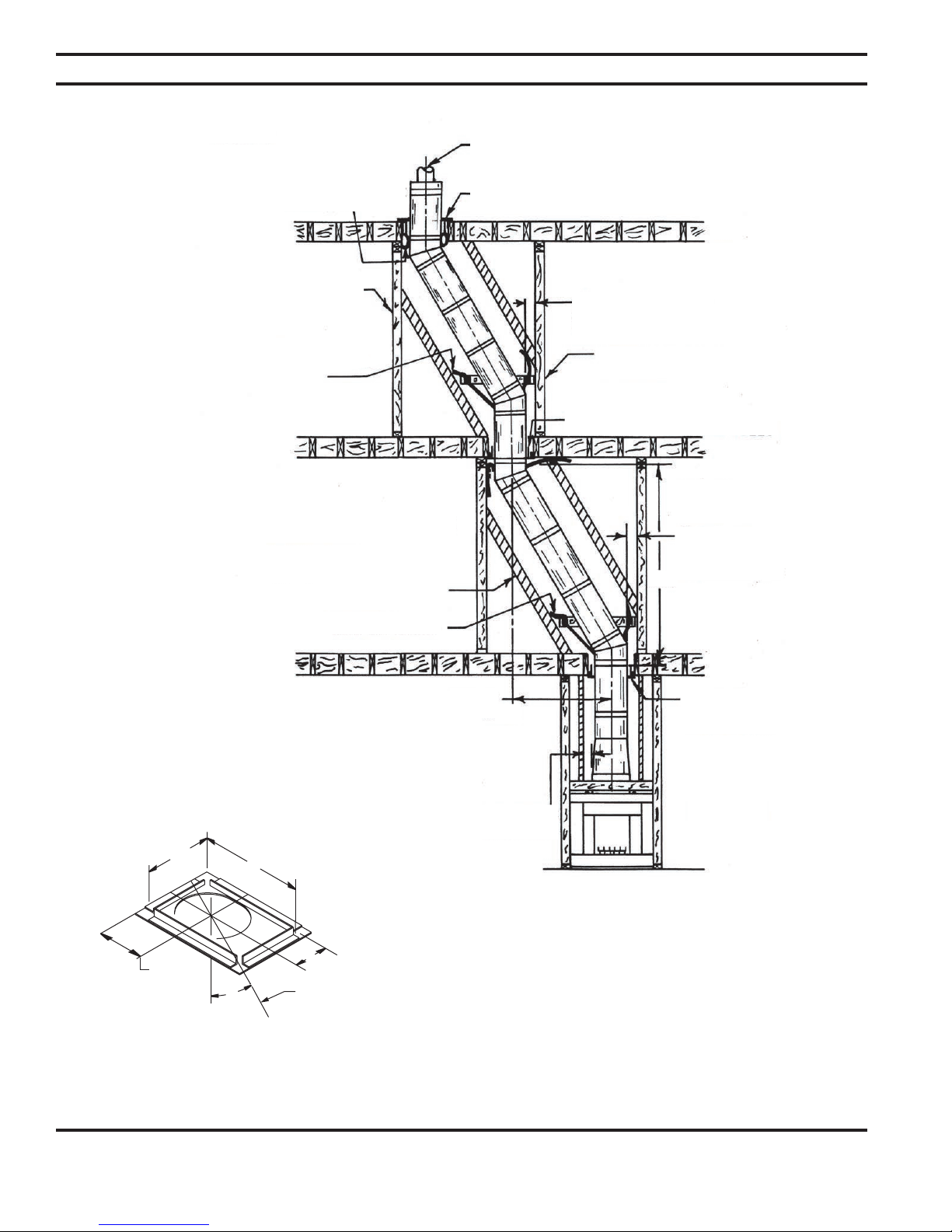
B36LA & B36RA Woodburning Fireplaces
17”
22
”
7”
30°
7”
CHIMNEY OFFSET AND CAP INSTALLATION
Figure 21
Support Straps Not
to Penetrate Firestop
Vertical Chimney
Enclosure
Fasten All Support
Straps Securely
Vertical Chimney Enclosure
Recommended.
Diagonal Chimney Enclosure
Acceptable
Diagonal Chimney
Enclosure
Support Straps
Continue chimney through roof
and install round chimney cap
or chimney housing
Firestop Spacer 1³⁄₄” Minimum Air
Space Clearance at Joist.
Chimney Must Be Enclosed in
Accessible Areas
2” Min. Air Space
Clearance to
Combustibles
Vertical Chimney
Enclosure
Firestop Spacer 1³⁄₄” Minimum Air
Space Clearance at Joist.
Diagonal Chimney
Enclosure
2” Min. Air Space
Clearance to
Combustibles
RISE
Figure 22
NOTE: Four (4) elbows
may be used when total
installation height exceeds 21 ft.
Centerline of
Chimney
Offset Max 10’
2” Min. Air Space
Clearance to
Combustibles
Firestop Spacer
14¹⁄₂” x 14¹⁄₂”
Maximum four (4)
elbows Per Fireplace
FP2170
20
53D9041
Page 21
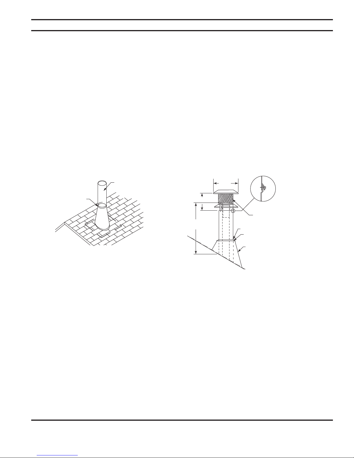
CHIMNEY CAP INSTALLATION
36” Min.
18
”
Dim. 7”
B36LA & B36RA Woodburning Fireplaces
Model SC Chimney Cap
SPECIAL NOTE: The proper height as previously explained is important to assure proper draft and safety. The chimney
cap extends the flue outlet four inches above the top of the last section of chimney. This should be kept in mind when
determining the proper height for the chimney. The chimney should not be extended more than 90 inches above the
supporting roof structure without additional support. In the case of an “A” frame type construction or other steep pitch
roofs that require more than 90 inches of chimney above the roof, a support should be attached to the chimney at the
90 inch level that is strong enough to support a wind load of 3-1/8 pounds for each inch the chimney extends above 90
inches. The flue outlet must be a minimum of three feet above the point where in penetrates the roof.
CAUTION: Be careful to avoid electrical shock hazard when contacting wires to the metal chimney components.
1. Extend the regular chimney sections until the top of the chimney is 4 inches below the total flue height desired. Do
not snap the last section of inlet air duct or largest diameter pipe in place until Step 3 is completed.
2. Remove the shingles from around the chimney so that the flashing may be installed, with the upper part of the flashing under the shingles.
3. Set the flashing on the roof and scribe a line around the flashing, then cut the top off the flashing by cutting 1/4 inch
below the scribed line. This should increase the diameter of the flashing outlet sufficiently to allow the flashing to be
placed over the chimney. Figure 23
4. Snap the last section of inlet air duct in place and slide the flashing over the chimney. Adjust the chimney to assure
that the proper minimum clearances are maintained.
Hold Inlet Air Duct
(Outside Pipe) Vertical
Scribe Line
at Bottom
Figure 23
Model SC/SCL
Round Chimney Cap
Apply Mastic Here
Storm Collar
FP1897
5. Nail the flashing securely in place with eight nails.
FP2171
Flashing
6. Seal the crack between the top of the flashing and the chimney with mastic. Leave some excess mastic at this area
to be used in step eight. NOTE: Use pliers and wear gloves when performing step seven to minimize the danger of
cutting your hands on the edge of the storm collar.
7. Place the storm collar around the chimney and put the collar together like a belt in belt loops. Slide the end of collar
under the two loops on the other end with the loops facing up. Overlap the ends of the collar until it is tight against the
chimney. Bend the free end of the collar back over the loops to hold the storm collar securely together. The excess
end of the storm collar may be trimmed off.
8. Slide the storm collar down snugly against the flashing until the excess mastic left in step six is forced up into the
crack between the storm collar and the chimney. This should make the joint between the flashing and the chimney
watertight.
9. Install the chimney cap by placing the cap into matching parts of the last chimney section. Push down until the brackets on the bottom of the chimney cap sit on the chimney pipe. Then punch or drill 1/8 inch diameter holes in the inlet
air duct (chimney pipe) where specified on the brackets and fasten it down with the No. 8 screws provided. Do not
penetrate the inner stainless steel pipe while installing the screws.
10.Check all the parts of the fireplace, chimney and chimney termination cap to assure that no parts have been damaged or bent during installation and that all parts have been installed properly.
NOTE: The metal used for the chimney cap has a rust protective coating but the cut edges of the parts are not protected. To prevent rusting and rust staining of nearby structures, exposed parts of the chimney and chimney cap should
be detergent washed and painted with a galvanized primer paint.
53D9041
21
Page 22
B36LA & B36RA Woodburning Fireplaces
OUTSIDE COMBUSTION AIR PRECAUTIONS & RECOMMENDATIONS
NOTE: The use of outside air for combustion is optional unless required by building codes. It is
only necessary to supply outside combustion air to one side of the fireplace. Use the Model OAC4
combustion air kit.
Outside Combustion Air Recommendations
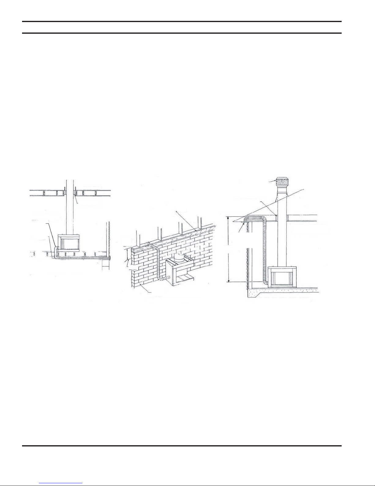
1. Extremely long runs and numerous turns in the duct leading from the fireplace to the combustion
air assembly should be avoided. These conditions will increase the resistance to the free flow
of air through the duct. Refer to Figure 24 for methods of installing the outside air for combustion assemblies.
2. The combustion air assembly should be located at an exterior location, which is not likely to be
accidentally blocked in any manner. The assembly should be located above the snow line to
prevent blockage by snow accumulation.
3. The combustion air inlet assembly should never be mounted in a garage or storage area where
combustible fumes such as gasoline might be drawn into the fireplace.
4. Combustion air can be drawn form the crawl space under a house when an adequate supply of
air is provided by open ventilation.
5. Do not take combustion air from attic space or garage space.
Duct Extedned to
Miss Joist
-
To Out
side Wall
Installation Above Basement or Crawl Space
Figure 24
Second Floor
Firestop
Spacer
Above
snow
Level
Plate
Basement Wall
Basement Installation
8’ Max.
Termination Cap
Firestop
Spacer
Inlet Grille in
Soffit (Over
hang)
-
Concrete Slab Installation
CAUTION: Do not
take combustion air
from attic space or
garage
FP2172
22
53D9041
Page 23
COMBUSTION AIR ASSEMBLY
1 2 3
2“
App.
Loop Disengaged
Clamp Around
Duct
Slip Band
Through
Housing
Snap Screw
Down and
Tighten
Approximately
2”
B36LA & B36RA Woodburning Fireplaces
Model OAC4 Combustion Air Assembly
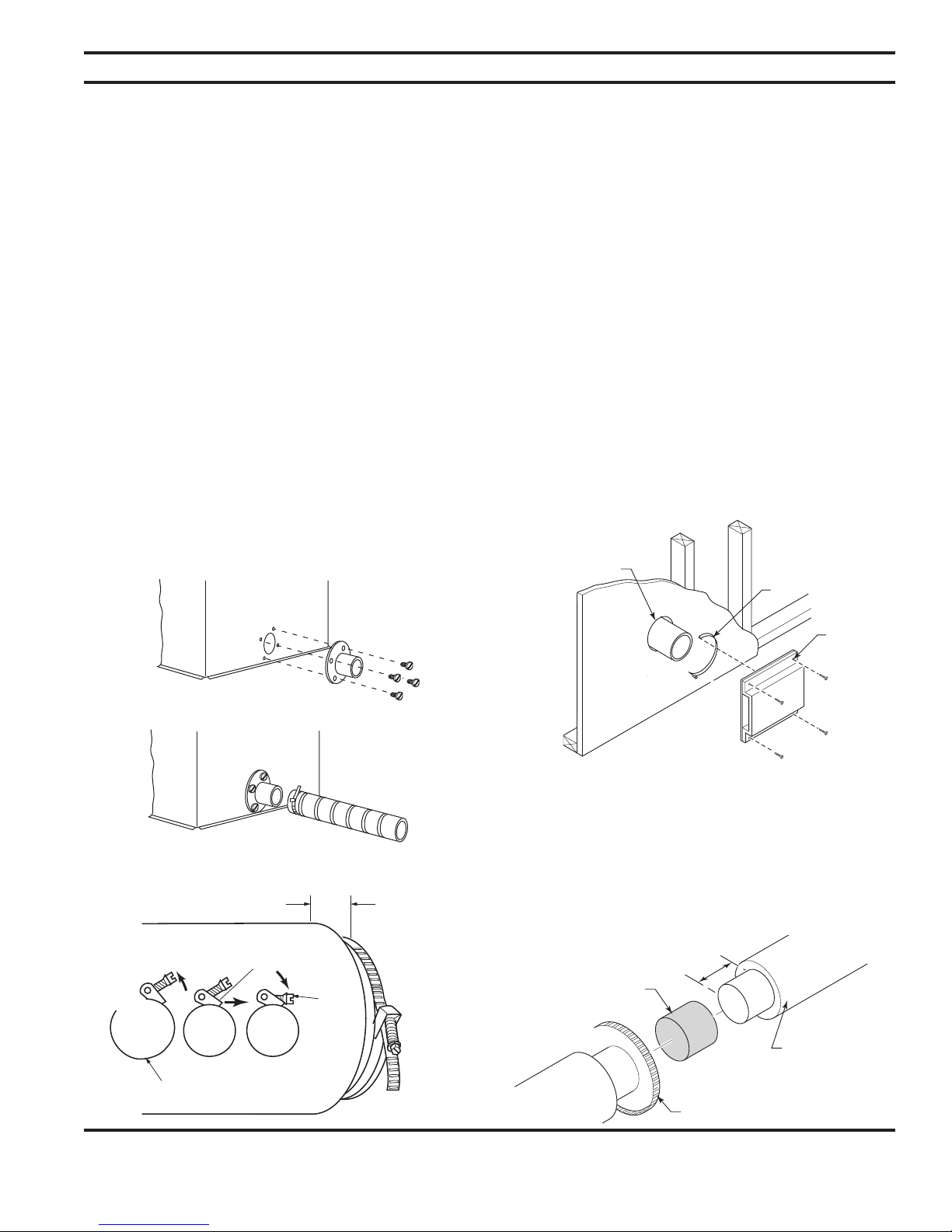
1. Remove the cover cap from the 4” outlet opening location on the left or right outside surface of the fireplace. DO NOT
REMOVE THE COVER IF THE OUTSIDE AIR WILL NOT BE CONNECTED.
2. Fasten the 4” starting collar over the hole on the left or right side of the fireplace with the four (4) sheet metal screws
provided. Figure 24
3. Cut a 6” diameter opening for model OAC4 in the outside wall covering where the model OAC4 outside grille is to be
located. Figure 26
4. Select and cut a piece of duct of sufficient length to attach to the fireplace and protrude at least 3” beyond the face of
the wall to which the OAC4 inlet air box assembly will be attached. The duct may be cut with a standard pocket knife.
Use FP-4-U duct for maximum efficiency and safety. Do not use a combustible duct. Always use UL listed Class 0 or
1 duct material.
5. If the duct is the insulated type, push the insulation back from one end of the duct approximately 2”. Figure 27
6. Slip the exposed end of the duct over the flange tube of the fireplace.
7. Place the duct clamp around the exposed end of the aluminum duct.
8. Slip the band through the housing, then pull the band tight around the duct.
9. Snap the band locking screw down and tighten it with a screwdriver or nutdriver. Figure 27
10.Nail or screw the combustion air assembly to the surface of the wall.
NOTE: If the wall covering is brick or stone, use appropriate masonry fasteners. Mount the combustion air assembly
with “TOP” up to prevent rain from entering the assembly. Be sure the 6” diameter opening around the air duct is sealed
with insulating material to prevent cold air from entering through the wall. If it is necessary to splice the duct, a model
403 duct connector should be installed as described in Figure 26.
Attach Outside Air Starting Col
lar to Fireplace
-
Figure 25
Figure 26
6” Dia.
Hole
Clamp
Figure 27
53D9041
Step 1
Attach outside air starting collar to
left or right side of fireplace with four
(4) sheet metal screws provided.
Step 2
FP2173
Attach outside air duct to starting
collar with duct clamp.
Band
Screw
FP1906
Nail Holes
FP1904
Combustion Air Assy. Model OAC4
Installation of the Model 403 Duct Connector
1. Push the insulation back approximately 2” from the end of each
duct.
2. Slip each duct over the duct connector until an equal length of the
connector extends into each duct.
3. Place a duct clamp over the end of each duct and tighten it down
snugly.
4. Push the insulation back into place and over the duct clamp.
Duct Connector
Figure 28
Insulation
FP1907
Duct Clamp
23
Page 24

B36LA & B36RA Woodburning Fireplaces
WARNING: Improper installation or operation of a gas appliance in this fireplace can allow unburned
gas to leak out which will cause a fire or explosion hazard, or the release of poisonous carbon monoxide into the dwelling which can cause serious injury or death to its inhabitants. To reduce these risks to
a minimum, the following important notices and instructions should be read and followed carefully.
IMPORTANT NOTICES:
1. The provision for a gas line is intended for connection to a decorative gas appliance which and
complies with the Standard for Decorative Gas Appliances for Installation in Vented Fireplaces,
ANSIZ21.60. If a decorative gas appliance is installed, it must be installed in accordance with the
National Fuel Gas Code, ANSIZ223.1.
CAUTION: “When a decorative gas appliance is installed, the fireplace damper must be fixed in a
manner which will maintain the minimum permanent vent opening at all times.”
WARNING: This fireplace has not been tested with an unvented gas log set. To reduce risk of fire
or injury, do not install an unvented gas log set into fireplace.
The installer of the fireplace and gas appliance must describe the operation of the fireplace and ap-
pliance to the people who will be operating them and leave all instruction manuals with the operator
of the appliance.
2. An approved gas shut off valve must be located outside the fireplace in an area accessible to the
users of the fireplace.
3. All gas piping and fitting must be either steel or malleable iron.
4. Some code authorities prohibit or place restrictions on the use of gas appliances in fireplaces.
Check with local code authorities before proceeding with the installation.
5. The gas appliance and all connecting gas piping should only be installed by a licensed gas appliance installer. Refer to Page 14, Figure 11 for the gas line opening dimensions on the fireplace.
The following instructions only apply to passing the gas line through the fireplace wall. Follow the instructions provided by the appliance for the gas line, testing and adjusting it.
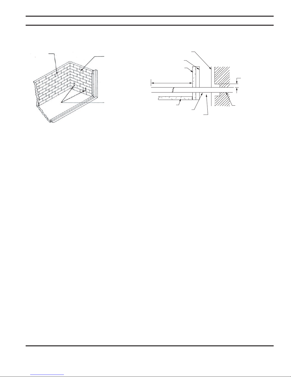
1. Remove the side brick form the fireplace and locate the dimple “B” referred to by
2. Tap out a round hole in the brick liner with a hammer by tapping lightly on the recessed area.
3. Remove the two screws that hold the cover plate on the jacket wrap and discard the cover plate.
4. Use a screwdriver or similar tool to push the loose insulation out of the tube between the firebox and
the outer jacket of the fireplace.
5. Install the gas pipe through the tube between the firebox and jacket.
6. Attach the gas appliance to the gas pipe according to the instructions provided with the gas appliance.
7. Pack the insulation removed in Step 4 around the pipe to prevent air flowing through the tube either
into or out of the firebox.
8. Be sure the gas is turned off at the appliance, then turn the gas on at the cut off valve and test the
gas line connections for leaks with soapy water solution or a liquid leak detector. DO NOT USE A
MATCH OR OTHER FLAME SOURCE TO CHECK FOR GAS LEAKS. If a gas leak is detected, turn
the gas off immediately and fix the leak.
9. Proceed with installation and adjustment of the gaas appliance as directed by the instructions provided with the gas appliance. If a gas leak is detected, turn the gas off immediately and fix the
leak.
GAS APPLIANCE INSTALLATION
Figure 29.
24
53D9041
Page 25
GAS APPLIANCE INSTALLATION
B36LA & B36RA Woodburning Fireplaces
Figure 29
Back Refractory
Brick
CAUTION: When using a gas appliance, the fireplace damper must be set in fully open position.
Installation of Gas Appliance in Fireplace
Side Refractory
Brick
Dimple
Outer Fireplace Wrap
Inner Fireplace Wrap
Side Brick
26” Max.
Fireplace Firebrick
Hearth Brick
Gas Line Access Tube
Repack Insulation Around
Gas Line Where it Passes
Through Gas Line Access
Tube for Proper Seal
Maintain 1/2”
Minimum Air
Space Clearance
to Combustibles
for Gas Line Out
to 4” From Side
of the Fireplace
Combustible Materials May Be Located
at Zero Clearance
to Gas Line Beyond
4” From Fireplace
Side.
TRIM INSTALLATION
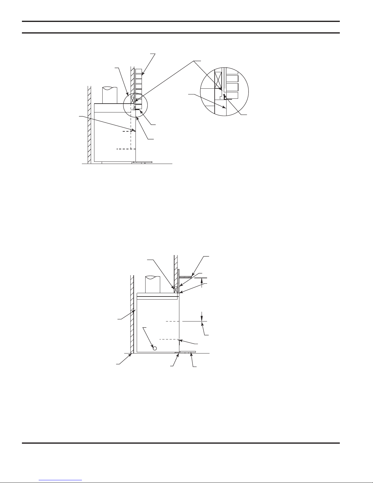
The face of your fireplace may be left exposed or trimmed with any noncombustible material such
as brick, stone or marble. Figure 30. If a noncombustible trim is installed, be sure it is fastened
snugly to the face of the fireplace. A crack between the material and the face of the fireplace could
pose a fire hazard and impair the proper operation of the fireplace. Blocking the fireplace with framing and attaching the base to the supporting floor will further reduce the possibility of such a crack
developing.
CAUTION: Do not allow any trim materials to extend closer than 3/8” to the vertical edges of the
firebox opening if you plan to equip the fireplace with glass doors.
Wall ties should be fastened to the face of the fireplace with sheet metal screws and placed in the
mortar joints of masonry trim.
Combustible material must not be installed below the top spacers of the fireplace or overlap the
sides of the fireplace face. Seal the face of the fireplace to the surrounding wall with noncombus
tible caulk or trim materials to prevent cold air leakage around the fireplace.
CAUTION: No trim should block or restrict in any way the flow of air into the air inlets in the face of
the fireplace. Figures 30 and 31
Be sure to provide the required floor protection as described in a preceding section of this manual.
Page 13, Figure 10
Combustible mantels and trim must be installed in accordance with the National Fire Protection
Association - ANSI NFPA 211 Standard - Section 7-2.3.3.
Glass Door Installation
This fireplace has been tested and listed for use with Model MGD36B or MGD36PB glass doors.
For installation of the Model MGD36B or MGD36PB glass doors, refer to the instructions provided
with the doors.
-
53D9041
25
Page 26
B36LA & B36RA Woodburning Fireplaces
TRIM INSTALLATION
Installation of Noncombustible Facing Materials to the Front Face of the Fireplace
Figure 30
Do Not Install Combustible
Framing or Trim Below Top
Edge of Fireplace
Top of Fireplace
Opening
* For B Models, facing
materials can be brought
to the top of the fireplace
opening
Noncombustible Facing
Material
Fireplace Face
Steel Lintel
(Optional)
CAUTION: Do not cover or
restrict vent areas with any trim
materials.
M1021
Use Only Noncombustible Materials
Below Top of Spacers
WARNING: The space between the face
of the fireplace and the noncombustible
facing material must be sealed. Failure to
properly seal this crack can cause a possible fire hazard and will void the MHSC
warranty.
CAUTION: Do not allow any trim materials to extend closer than 3/8 inch to the vertical edges of the
firebox opening if glass doors are to be installed.
NOTE: On B36LA or B36RA Models, noncombustible facing materials may be installed to the top of
the fireplace opening. This facing material must be secured and sealed to the face of the fireplace.
Failure to properly secure and seal noncombustible facing material to the fireplace can cause a
possible fire hazard and will void the warranty.
Mantel Installation
Figure 31
Do Not Install Combustible
Framing or Trim Below Top
Edge of Fireplace
1” Air Space to Rear
of Fireplace
1/2” Air space to Side
of Fireplace
Insulate Outer and Inner
Walls of Chase Always Maintaining Proper Clearance
M1002
Safety Strip
Outside
Air Inlet
Combustible Mantel
Do Not Install Combustible
Facing Material Below Top
Edge of Fireplace
Top Edge of Fireplace
18” Min. From Fireplace Opening to
Bottom of Combustible Mantel
(Manufacturer Recommendation)
Top Edge of Fireplace Opening
Air Inlet Opening
CAUTION: Never block bottom air
Hearth Extension
inlet opening. Covering the bottom air inlet openings of the fireplace may cuase a fire hazard.
26
53D9041
Page 27

FIREPLACE OPERATION
WARNING: If a decorative gas appliance is used in the fireplace the fireplace damper must be
fixed in an open position. (See additional operation information in section titled “Operation Guidelines”.)
B36LA & B36RA Woodburning Fireplaces
Which Woods Are Best?
Each wood species offers something different in aroma or heat value, and you should consider
your needs and desires before building your fire.Softwoods, like pine, spruce, and fir are easy to
ignite because they are resinous. However, a fire built entirely of softwoods burns out quickly and
requires frequent replenishment. While a softwood fire is not too desirable for a long evening, it’s
fine in the morning when you want quick warmth, or late in the evening when you want a fire that
will burn out before you go to bed.On occasion when a longer fire is desired, it’s best to combine
softwoods with the heavier hardwoods such as ash, beech, birch, maple, oak and hickory. These
hardwood species burn less rapidly, with shorter flames, and produce steady, glowing coals.For the
most pleasing aroma, you’ll want to burn the wood of fruit trees such as apple and cherry, or nut
trees such as beech, hickory and pecan. Such wood is generally more expensive, but a little combined with other wood, goes a long way. Start your fire with a mixture of softwood and hardwood,
then add some fruit or nut wood for nostalgic aroma. Since most woods will not burn well when
freshly cut, the wood you purchase should be reasonably dry. The sizes you buy are dictated by
the size of your fireplace. Purchase logs that will fit when laid across your grate, and ask that the
larger, heavier logs be split. Kindling should be short, easily split lengths of softwood, lumber yard
or mill scraps, or twigs and branches gathered from your yard.
How To Build A Better Fire
The first three fires should be of moderate size to allow the fireplace to adjust and the bricks to cure
before being subjected to larger fires. First, make sure your room is well ventilated, your damper
open and the flue is unobstructed. Then make sure your wood is dry and seasoned. Unseasoned
wood burns poorly and coupled with poor ventilation or an obstructed chimney, leads to smoking
problems.If your fireplace is equipped with an outside combustion air assembly, open the combustion air inlet by pushing upward on the lever located above the firebrick on the left side of the
firebox.
NEVER USE GASOLINE, GASOLINE-TYPE LANTERN FUEL, KEROSENE, CHARCOAL
LIGHTER FLUID, OR SIMILAR LIQUIDS TO START OR “FRESHEN UP” A FIRE IN THIS FIREPLACE. KEEP ALL SUCH LIQUIDS WELL AWAY FROM THE FIREPLACE WHILE IT IS IN USE.
USE OF THIS FUEL CAN CAUSE A SERIOUS EXPLOSION.
Prepare your fire by placing two logs on the iron grate or fire basket, and laying the tinder between
them. Tinder may be dry scrap paper, twigs, or bark. On top place a small handful of twigs or split
softwood kindling. Place more dry logs over this base. Keep logs close together, as narrow air
spaces between them promote better drafts, and heat reflected between adjacent surfaces aids in
raising and maintaining combustion temperatures.
You’ll need a minimum of three logs, preferably four, to make a good fire. Add kindling and new
logs as needed to rekindle a dying fire. New logs should be added at the rear grate after raking
the coals toward the front. DO NOT OVERFIRE THE FIREPLACE. Overfire conditions may be
created by large amounts of kindling, building scraps, or other improper fuels.
Ashes, important because they form a bed of glowing coals, should only be left to accumulate
within an inch or two of the bottom of the grate. Excess ashes can be used to check a flaming fire;
or to “bank” your fire, cover the logs with ashes. A “banked” fire will hold glowing coals for 8-10
hours, thereby saving a fire for later use.
53D9041
27
Page 28

B36LA & B36RA Woodburning Fireplaces
FIREPLACE OPERATION
Wood vs. Fossil Fuels
Compared to fossil fuels, a full cord of dry hickory weighs about two tons and is approximately equal in
heating value to a ton of hard coal. On a pound basis, heavy hardwoods have about half the heating
value of coal. The tabulation shows the relative densities and heat values of a variety of dry woods.
Varieties at the top of the list (Dogwood) burn longer and those near the bottom (White Pine) ignite and
burn quicker. A combination of both light and heavy wood is desired.
Species Density Heat Value Species Density Heat Value
Dogwood .70-.79 100-107 Ash .57-.61 81-82
Hickory .70-.74 100 Southern Pine .51-.60 73-81
Oak .60-.73 86-99 Elm .50-.59 71-80
Black Locust .69-.70 95-98 Cherry .50-.52 70
Beech .64-.66 89-91 Douglas Fir .45-.51 64-69
Hard Maple .58-.65 83-88 Spruce .41-.44 59
Birch .55-.64 79-86 Redwood .33-.40 47-54
Apple .58-.62 83-84 White Pine .35-.37 50
A Few Words Of Caution
Beware of burning certain material in your fireplace. Among these are plastics, poison ivy twigs and
stems, and chemically treated woods such as discarded poles and railroad ties. These not only create
air pollution, but can induce extreme irritation for some individuals.
Use hemlock, spruce, juniper and other resinous woods with caution. They contain moisture pockets
which, upon heating, “pop” with considerable vigor.
Always use a fire screen. And always “bank” a fire, or at least push all unburned fuel to the rear of the
grate before leaving a fire unattended. Do not use this fireplace as an incinerator.
Because the termination of the chimney above the roof is exposed to wind and cold and the pressure
changes these and other environmental conditions may cause, a sufficient chimney draft may be hard
to establish at times. At other times the draft may be sufficiently disrupted to cause smoke to spill from
the fireplace opening. If problems with chimney draft occur, help start chimney draft before you build
a fire by holding a piece of burning paper near the flue opening at the top of the firebox to preheat the
chimney. If smoke spills from the fireplace opening after the fire is burning, open a window on the up
wind side of the house that is far enough away form the fireplace that the wind will not blow across
the fireplace opening, push the burning wood as near the back of the fireplace as possible, and if the
fireplace is equipped with glass doors, close them.
DO NOT LEAVE CHILDREN OR PHYSICALLY OR MENTALLY HANDICAPPED, OR SENILE PERSONS ALONE WITH A BURNING FIREPLACE.
28
53D9041
Page 29

MAINTENANCE & SAFETY
B36LA & B36RA Woodburning Fireplaces
Fuel Storage
Wood can be dried sufficiently for burning within a few weeks if protected form rain in a low humidity area. It is far better to cut wood and allow it to dry for a year. In all cases, the wood should be
stacked so that both ends of the sticks are exposed to the air and protected from rain. The drier
the wood, the more usable heat produced by the fire and less likely rapid accumulation of soot and
creosote within the chimney is to occur. See the section of this manual concerning chimney maintenance for information concerning the hazards of soot a creosote accumulation. Small quantities
of wood required for fire tending must be kept at least 30 inches from the fireplace.
Disposal Of Ashes
Ashes should be placed in a metal container with a tight fitting lid. The closed container of ashes
should be placed on a noncombustible floor or on the ground well away from all combustible materials pending final disposal. If the ashes are disposed of by burial in soil or otherwise locally
dispersed, they should be retained in the closed container until all cinder has thoroughly cooled.
Ashes should never be placed in a container with combustible materials.
Chimney Maintenance
Creosote, Formation and Need for Removal: When wood is burned slowly, it produces tar and
other organic vapors, which combine with expelled moisture to form creosote. The creosote vapors
condense in the relatively cool chimney flue of a slow-burning fire. As a result, creosote residue
accumulates on the flue lining. When ignited, this creosote makes an extremely hot fire.
The chimney should be inspected at least twice a year during the heating season to determine if a
creosote buildup has occurred.
If creosote has accumulated it should be removed to reduce the risk of a chimney fire.
The chimney cap can be removed for inspection, maintenance and cleaning by removing three
screws from the support legs and lifting upward.
When the fireplace is first in use, inspect the chimney frequently and clean the chimney any time an
accumulation is observed on the flue walls. The frequency of these inspections can be increased
or reduced appropriately after a pattern of accumulation has been established. Please note, however, that changes in the outside environmental conditions such as temperature and humidity or
changes in the operation of the fireplace can lead to rapid buildup of soot and/or creosote.
To clean the chimney, obtain the services of a qualified and reputable chimney sweep, or remove
the accumulation with brushes on wooden or fiberglass poles. Do not use metal pipes, chains,
wires, etc., to clean the chimney because such items can scratch the surface of the stainless steel
flue which can shorten the life of the flue and provide a rough surface for soot particles to attach
to.
Be sure to cover nearby furnishing and arrange some method of catching soot and creosote parti
cles that may fall during the chimney cleaning process. If glass doors are installed on the fireplace,
they should be closed. Extra caution must be used to avoid damage to the flue damper during the
cleaning process.
In addition to checking and cleaning the chimney on a regular basis, be sure to inspect the chimney
before starting a fire at the beginning of each heating season. Make sure the chimney is clear from
any accumulation of soot, creosote or any other debris, and that all joints are intact.
MHSC does not recommend chemical cleaners because some may contain elements that corrode
the metal parts of the chimney or fireplace.
-
53D9041
29
Page 30

B36LA & B36RA Woodburning Fireplaces
MAINTENANCE & SAFETY
Fireplace Maintenance
At the end of each heating season or when the fireplace will not be in use for an extended time, the
ashes should be removed and the hearth area should be swept as clean as is practical. The slow absorption of moisture into the ashes over a long period of time could cause a condition which would be
corrosive to the metal fireplace parts.
At the beginning of each heating season, always operate the flue damper and make sure it has not
become stuck from soot, creosote, etc., during the period of inactivity.
Keep the lower and upper grille panels clean and free from dirt and lint accumulation at all times to get
the maximum efficiency from your fireplace.
As you use the fireplace, expansion and contraction will cause minor cracking of the hearth, back, and
side refractory materials. This is normal and unavoidable. If the cracks become large enough or parts
dislodge and metal behind the refractory is exposed, the refractory panels should be replaced with new
panels that can be obtained from you fireplace dealer.
Glass Door Maintenance
For glass door maintenance, see instructions provided with the glass doors.
Checklist of Do’s and Dont’s
DO’S
1. Do check with local building officials to be sure the installation of the fireplace complies with all
building codes and requirements and obtain required building permits. Do plan your installation with
safety as you primary consideration.
2. Do use only the prescribed material and parts for the installation of the fireplace.
3. Do insulate the exterior walls surrounding the fireplace to prevent excessive heat loss from the
fireplace.
4. Do trim the face of the fireplace only with noncombustible materials.
5. Do attach the noncombustible face trim material firmly to the face of the fireplace.
6. Do block in or fasten the fireplace to prevent the possibility of the fireplace shifting out of position.
7. Do connect the air circulation blower to a properly grunded and fused electrical circuit.
8. Do enclose the chimney where it passes through living spaces or spaces accessible for storage
purposes to prevent contact with and possible damage to the chimney.
9. Do install firestop spacers at each ceiling level when the chimney is installed in a multistory build
ing.
10. Do install the proper chimney cap or chimney housing on the chimney to prevent rain and debris
from entering the chimney.
11. Do keep all flammable liquids, gases and pressurized containers away form the fireplace.
12. Do check the fireplace for proper adjustment and operation before leaving it unattended for long
periods of time.
13. Do inspect and clean the fireplace chimney regularly.
14. Do keep the fire screens closed when the fireplace is left unattended to minimize the danger of
sparks popping out of the fireplace.
15. Do use the grate furnished with and for this fireplace.
16. Do start a fire only with paper, kindling or solid composition fire starters specifically designed for
starting a fire. The use of liquid fire starter can cause an explosion within the fireplace.
17. Do place all ashes in a metal container with a tight fitting lid and place them on a noncombustible
surface well away from other combustible materials until they have completely cooled.
18. Do store your fuel supply at a distance equal to or greater than the spacing recommended for com-
bustible materials from the fireplace.
19. Do build fires of moderate intensity in the fireplace for the first three fires to allow materials to adjust
and cure before being subjected to the intense heat of a large fire.
-
30
53D9041
Page 31

MAINTENANCE & SAFETY
DONT’S
1. Don’t allow other installations or operation considerations to take priority over safety considerations.
2. Don’t attempt to use the fireplace until the installation is complete.
3. Don’t use unlisted parts and accessories with the fireplace except for special flashings that may be
fabricated locally.
4. Don’t use damaged parts or accessories with this fireplace.
5. Don’t install the fireplace in an exposed or uninsulated area.
6. Don’t install the fireplace over carpeting.
7. Don’t install the fireplace on a poorly constructed base or fail to fasten down or attach the fireplace to
prevent it from shifting out of position.
8. Don’t create or allow a crack to develop between the metal face of the fireplace and noncombustible
trim.
9. Don’t use power blowers or air circulation systems with this fireplace that are not specifically recommended by MHSC.
10. Don’t connect accessory air circulation blowers to improperly fused or ungrounded electrical circuits.
11. Don’t install the fireplace where flammable or explosive liquids or vapors are likely to be present.
12. Don’t neglect all the considerations mentioned in this manual concerning clearances to combustibles,
spacing from obstructions and proper chimney height when selecting the location and installing the
chimney.
13. Don’t allow insulating materials to contact the chimney.
14. Don’t neglect to apply caulking or mastic to the required joints of the flashing and between the flashing
roof.
15. Don’t dry clothing or other articles near the fireplace.
16. Don’t store or place flammable liquids, gases or pressurized containers near the fireplace.
17. Don’t neglect to instruct all responsible persons in the proper and safe operation of the fireplace.
18. Don’t fail to instruct all persons, especially children and elderly persons, concerning the hazards of
improper operation and unauthorized tampering with the fireplace.
19. Don’t use this fireplace to burn paper, cardboard, or other debris.
20. Don’t neglect to inspect and clean the chimney regularly.
21. Don’t operate the fireplace with the glass fire screen doors partially open. The doors should always be
fully open or fully closed.
22. Don’t use gasoline, kerosene, engine oil,or charcoal lighter fluid.
23. Don’t store fuel supply closer to the fireplace than the minimum spacing required for combustible materials.
24. Don’t subject the fireplace to the intense heat of a large fire the first three times the fireplace is used,
but build moderate fires to allow the materials to cure and adjust.
25. Don’t clean the chimney with metallic devices or chemical cleaners.
26. Don’t use the fireplace or chimney for venting wood or coal burning heaters or inserts unless approved
in writing by MHSC.
27. Don’t put combustibles within 24 inches of the fireplace opening.
“WARNING: IF NOT INSTALLED, OPERATED AND MAINTAINED IN ACCORDANCE WITH THE MANUFACTURERS INSTRUCTIONS, THIS PRODUCT COULD EXPOSE YOU TO SUBSTANCES IN FUEL
OR FROM FUEL COMBUSTION WHICH CAN CAUSE DEATH OR SERIOUS ILLNESS AND WHICH
ARE KNOWN TO THE STATE OF CALIFORNIA TO CAUSE CANCER, BIRTH DEFECTS OR OTHER
REPRODUCTIVE HARM. ALSO, OPERATION, INSTALLATION AND SERVICING OF THIS PRODUCT
COULD EXPOSE YOU TO AIRBORNE PARTICLES OF GLASS WOOL FIBERS KNOWN TO THE STATE
OF CALIFORNIA TO CAUSE CANCER THROUGH INHALATION.”
B36LA & B36RA Woodburning Fireplaces
53D9041
31
Page 32
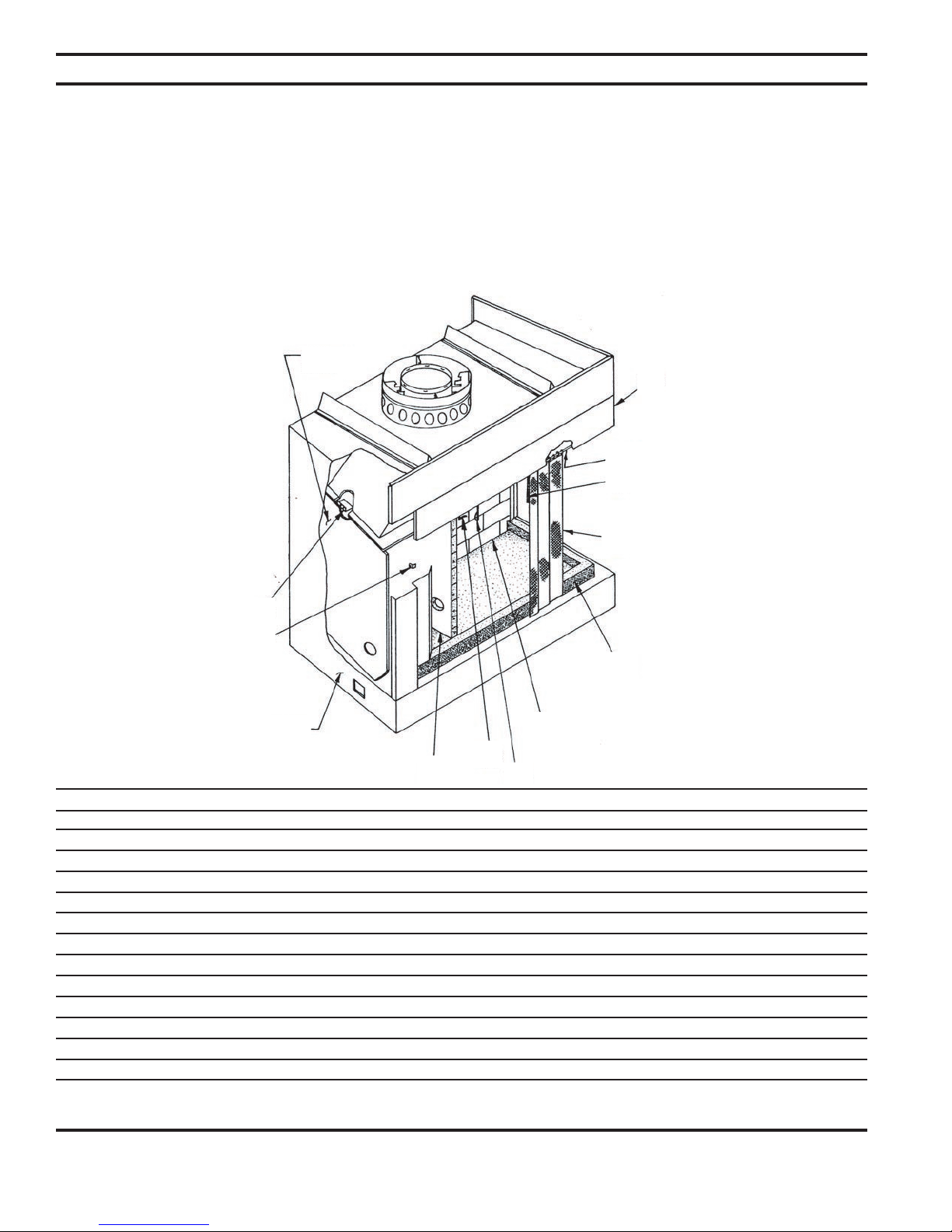
B36LA & B36RA Woodburning Fireplaces
1
2
3
4
5
6
7
8
9
10
11
PARTS DIAGRAM AND LIST
All repair part orders should be placed through your local dealer. To ensure prompt and accurate service, please provide the following information when placing a repair part order: Model number of your
Appliance, Part Name, Part Number, and Quantity of parts needed.
Technical Service Department
MHSC
149 Cleveland Drive
Paris, KY 40361
www.mhsc.com
Firebox Wrap
Jacket Wrap
Item Description Qty. B36RA B36LA
1. Retainer Side Brick 1 020270 020270
2. Retainer 2 Z19901 Z19901
3a. Firebrick Side Assy. Right 1 014012 - 3b. Firebrick Side Assy. Left 1 -- 021663
4. Rod Outside Air 1 020293 020293
5. Firebrick Back Assy. 1 014048 014048
6. Hearth Refractory 1 029986 029986
7. Screen Panel 2 026400 026400
8. Screen Pull 2 026391 026391
9. Rod Screen Weld Assy. 1 021673 021673
10. Panel Upper Painted 1 021541 021541
11. Rod Damper 1 037390 037390
12. Damper Weldment 1 037393 037393
32
53D9041
Page 33

B36LA & B36RA Woodburning Fireplaces
53D9041
33
Page 34

B36LA & B36RA Woodburning Fireplaces
34
53D9041
Page 35

LIMITED WARRANTY
B36LA & B36RA Woodburning Fireplaces
FACTORY-BUILT FIREPLACE AND COMPONENTS
(except blowers)
What is Covered and For How Long
• Five-Year Coverage - For five years from the date this fireplace and components are first purchased for use,
MHSC will, at its option, repair or replace any defective part of this fireplace or components, or refund to you a sum
not to exceed the factory retail price in effect at the time of purchase.
• Ten-Year Coverage - From the sixth through the tenth year following the date this fireplace or accessory is first
purchased for use, MHSC will make available to you, at our factory, a free replacement for any defective part in this
fireplace or accessory.
• Twenty-Five-Year Availability of Replacement Parts - From the eleventh through the twenty-fifth year following
the date this fireplace or accessory is first purchased for use, MHSC will make available at our factory replacement
parts for this fireplace or accessory, which you may purchase for the list price current at the time your purchase
order is received.
What is Not Covered
This limited warranty does not cover:
• Transportation or shipping cost.
• The cost of a service call to diagnose trouble.
• Painted surfaces.
• Damage or defect caused by improper installation, accident, misuse, abuse or alteration.
• Poor ventilation of smoke or gases caused by air-conditioning and heating systems, exhaust fans or pressure dif-
ferentials produced by wind.
• Broken glass components.
• Cracks in ceramic and castable parts that do not affect safe operation.
• We do not warrant this fireplace to be in compliance with your local building code. Building codes vary greatly
throughout the country, and you should determine whether your local building code contains restrictions on the use
of this fireplace before you purchase it.
• Blowers or fans, which are warranted separately.
• Heat loss due to the passage of heat or air through or around the fireplace.
Also, under our five year coverage, we do not pay the cost of removal and replacement of any portion of the structure
in which the fireplace is situated, made necessary by the repair, removal or re-installation of the fireplace.
And under our twenty-five year warranty of availability of replacement parts, we only promise to maintain a supply of
replacement parts at our factory for you to purchase.
Limitations and Exclusions
1. No one has authority to add to or vary this limited warranty, or to create for MHSC any other obligation of liability in
connection with this fireplace and accessory.
2. MHSC shall not be liable for incidental, consequential, special or contingent damages you might suffer as a result
of its breach of the written warranty or any implied warranty. Some states do not allow the exclusion of limitation of
incidental or consequential damages, so the above limitations may not apply to you.
3. This warranty applies only to the original purchaser of the fireplace or to the original owner of the dwelling when the
fireplace is installed in a new dwelling and may not be transferred.
4. This warranty applies only to a fireplace sold and used in the United States.
Your Duties
This fireplace must be installed by a qualified installer according to your local building codes and installation instructions and operated according to the owner’s instructions. You must keep an invoice, canceled check or payment
record to verify the purchase date of the fireplace.
If Warranty Service is Needed...
1. Contact your supplier. Make sure you have your warranty, your sales receipt and the model/serial number of your
MHSC product.
2. DO NOT ATTEMPT TO DO ANY SERVICE WORK YOURSELF.
53D9041
35
Page 36

MHSC
149 Cleveland Drive • Paris, Kentucky 40361
www.mhsc.com
JANUARY 2009
53D9041 • Rev. 2
 Loading...