

MCVC
USER MANUAL
Version 1.0
MCVC
User Manual
2
INTRODUCTION
THE MCVC (Midi to CV Converter)
The MCVC is a four-channel MIDI (Musical
Instrument Digital Interface) to Control
Voltage (CV) converter. The MCVC is a
straightforward interface between the
Eurorack synthesizer system and devices
that communicate using the MIDI protocol. The MIDI CV Converter bridges the
gap between MIDI and Eurorack systems,
by converting MIDI messages to control
voltages, corresponding to eurorack signal
standards.
CONTENTS
The MCVC comes in a box and is fully
assembled and tested. Included are a 16pin IDC power cable and M3 mounting
screws + rack crash protection washers.
SUPPORT
If you have any further questions or queries
please contact:
support@majella-audio.com
SPECIFICATIONS
Below are the specifications of the MCVC.
!! Dimensions 128,5 x 70,8 (14 HP) x
15mm
!! Doepfer A-100 compatible
!! 16pin Power (
Using 5V rail!
)
!! Current usage: +12V 39mA, -12V
.25mA, 5V 30mA.
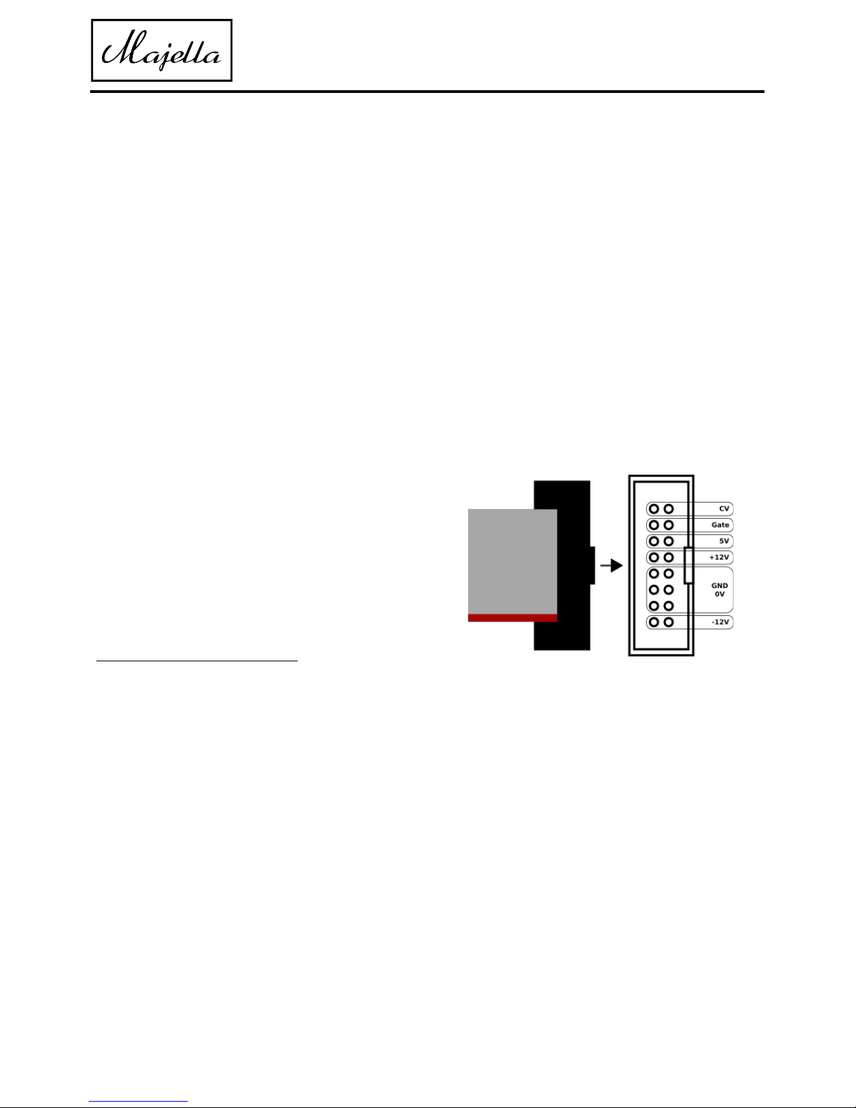
POWER CONNECTION
This Module is designed to be connected to
a Eurorack system power supply using a 16
pin ribbon cable. The -12V (red lead) should
be directed as shown in the picture below.
WARNING!
The MCVC is designed for Eurorack systems.
The supply should be +-12V and connected
signals should not be outside of the +-12V
range! Do not reverse polarity when
connecting the power, this will damage
your module permanently!
Please treat your Majella Audio products
with care. Majella Audio does not offer
warranty for any damages to the MCVC due
to irresponsible behaviour (fluid spills,
scratches, wrong input/output connections
etc.)

MCVC
User Manual
©2018 Majella Audio
3
OVERVIEW
1. MIDI INPUT
This is a 5 pin DIN MIDI input connector,
which makes it possible to connect MIDI
devices to the MCVC.
2. MONO POLY SWITCH
The Mono/Poly switch lets you choose how
the MCVC processes the incoming MIDI
Data. In MONO mode each channel is
controlled by the corresponding MIDI
channel number. E.g. MIDI Channel 1
controls voice 1, MIDI channel 2 controls
voice 2 et. In POLY mode the MCVC listens
to MIDI channel 1 and uses the next
successive voice available. E.g. if voice 1 and
2 are occupied it twill use channel 3 for the
next note to play.
3. MIDI BEAT CLOCK
This is a MIDI BEAT CLOCK output which
can be used to synchronise externally
clocked gear such as: delays, LFOs, drum
computers etc. It outputs 24 pulses per
quarter notes.
4 CHANNEL OVERVIEW
Each number corresponds with the three
outputs below (GATE, PITCH and VEL)
5 GATE OUTPUTS
The GATE outputs, output a 5V signal
whenever a “note ON” is played on the
corresponding channel. The LED blinks red
to indicate when a note is played.
6 PITCH OUTPUTS
The pitch outputs output a 1V/Oct signal
corresponding to the MIDI note number
received at the corresponding channel.

MCVC
User Manual
©2018 Majella Audio
4
7. VELOCITY OUTPUTS
The Velocity outputs output a 0-5V control
voltage corresponding with the Velocity
data received, E.g velocity 127 gives a 5V
signal. Lower MIDI velocity values output
lower control voltages.
8 PITCHBEND OUTPUT
This output converts Pitchbend MIDI
messages to a 0-5V CV-signal for
modulating/bending the pitch of oscillators.
Its initial state is 2.5V and it can bend it 2.5
octaves up or 2.5 octaves down. Of course it
can be used for other parameters as well.
9 MODULATION OUTPUT
The modulation output, outputs a voltage
in the range of 0-5V for CC1 (MOD) control
messages.
10 CC71 OUTPUT
CC71 is an extra CV output to control other
parameters of the Eurorack setup like VCF
resonance etc.
11. CC74 OUTPUT
CC74 is an extra CV output to control other
parameters of the Eurorack setup like VCF
cut off etc.

MCVC
User Manual
©2018 Majella Audio
5
EXAMPLE PATCH
The image below demonstrates a simple yet effective patch of the MCVC in combination with
an ADSR envelope generator, VCO and the Majella VVCA. The MIDI data from an external MIDI
device is fed into the MCVC with a 5 pin DIN cable. The data (pitch, velocity,) received from the
controller is converted to a voltage at the corresponding voice or channel output (depending
on the selected mode of the MCVC). The pitch output from the MCVC is connected to a VCO’s
V/OCT input to control the pitch of this oscillator. The Gate output of the MCVC is sent to an
ADSR to create an envelope. The velocity output of the MCVC is sent to the Velocity input of
the VVCA, but can also be sent to control other parameters e.g. resonance, accents, glide etc.
The output of the VCO is sent to the input of the VVCA. The output of the ADSR is sent to the
CV input of the VVCA, controlling the overall amplitude of the sound.

Special thanks to:
Rob Cottam
Ad Nieuwenhuizen
Erwin Tuijl
Lindsey Stuifbergen- van Steenis
Bas van Geuns
MCVC User Manual
version 1.0
06-12-2018
©2018
https://majella-audio.com
support@majella-audio.com
Designed and made in the Netherlands
 Loading...