


General Description
The MAX14802/MAX14803/MAX14803A provide highvoltage switching on 16 channels for ultrasonic imaging
and printer applications. The devices utilize HVCMOS
process technology to provide 16 high-voltage lowcharge-injection SPST switches, controlled by a digital
interface. Data is clocked into an internal 16-bit shift
register and retained by a programmable latch with
enable and clear inputs. A power-on reset function
ensures that all switches are open on power-up.
The MAX14802/MAX14803/MAX14803A operate with a
wide range of high-voltage supplies including VPP/V
NN
= +100V/-100V, +200V/0V, or +40V/-160V. The digital
interface operates from a separate +2.7V to +5.5V V
DD
supply. Digital inputs DIN, CLK, LE, and CLR operate
on the V
DD
supply voltage.
The MAX14803/MAX14803A provide integrated 35kΩ
bleed resistors on each switch terminal to discharge
capacitive loads. The MAX14802/MAX14803/
MAX14803A provide integrated clamping diodes for
overvoltage protection against positive overshoot.
The MAX14802 is available in a 48-pin TQFP package
and is specified for commercial 0°C to +70°C and
extended -40°C to +85°C temperature ranges.
The MAX14803 is available in a 48-pin TQFP package
and is specified for the commercial 0°C to +70°C temperature range.
The MAX14803A is available in the 110-bump wafer level
package (WLP) and is specified at the -40°C to +85°C
temperature range.
Applications
Ultrasound Imaging
Printers
Features
o Integrated Overvoltage Protection
o 20MHz Serial Interface (5V)
o HVCMOS Technology for High Performance
o Individually Programmable High-Voltage Analog
Switches
o Very Low 5µA (typ) Quiescent Current
o DC-to-20MHz Low-Voltage Analog Signal
Frequency Range
o 2.7V to 5.5V Logic Supply Voltage
o Low-Charge Injection, Low-Capacitance R
L
Switches
o -77dB (typ) Off-Isolation at 5MHz (R
L
= 50Ω)
o Daisy-Chainable Serial Interface
o Flexible High-Voltage Supplies (VPP- VNN= 230V)
MAX14802/MAX14803/MAX14803A
Low-Charge Injection, 16-Channel,
High-Voltage Analog Switches
________________________________________________________________
Maxim Integrated Products
1
Ordering Information/Selector Guide
19-4484; Rev 3; 8/11
For pricing, delivery, and ordering information, please contact Maxim Direct at 1-888-629-4642,
or visit Maxim’s website at www.maxim-ic.com.
PART
SWITCH
CHANNELS
BLEED RE SISTOR OVP PIN-PACKAGE TEMP RANGE
MAX14802CCM+ 16 No Yes 48 TQFP 0°C to +70°C
MAX14802ECM+ 16 No Yes 48 TQFP -40°C to +85°C
MAX14803CCM+ 16 Yes Yes 48 TQFP 0°C to +70°C
MAX14803AEWZ+ 16 Yes Yes 110 WLP -40°C to +85°C
Pin Configurations appear at end of data sheet.
+
Denotes a lead(Pb)-free/RoHS-compliant package.

MAX14802/MAX14803/MAX14803A
Low-Charge Injection, 16-Channel,
High-Voltage Analog Switches
2 _______________________________________________________________________________________
ABSOLUTE MAXIMUM RATINGS
ELECTRICAL CHARACTERISTICS
(VDD= +2.7V to +5.5V, VPP= +40V to VNN+ 250V, VNN= -40V to -160V, TA= T
MIN
to T
MAX
, unless otherwise noted. Typical values
are at T
A
= +25°C.) (Note 2)
Stresses beyond those listed under “Absolute Maximum Ratings” may cause permanent damage to the device. These are stress ratings only, and functional
operation of the device at these or any other conditions beyond those indicated in the operational sections of the specifications is not implied. Exposure to
absolute maximum rating conditions for extended periods may affect device reliability.
Note 1: Package thermal resistances were obtained using the method described in JEDEC specification JESD51-7, using a four-layer
board. For detailed information on package thermal considerations, refer to www.maxim-ic.com/thermal-tutorial
.
(All voltages referenced to GND.)
V
DD
Logic-Supply Voltage .......................................-0.3V to +7V
V
PP
- VNNSupply Voltage ....................................................230V
V
PP
Positive-Supply Voltage.................................-0.3V to +220V
V
NN
Negative-Supply Voltage ...............................-0.3V to -220V
Logic Inputs (LE, CLR, CLK, DIN, DOUT)................-0.3V to +7V
COM_, NO_...............................(-0.3V + V
NN
) to the minimum of
[(V
NN
+ 220V) or (VPP+ 0.3V)]
Peak Analog Signal Current Per Channel ................................3A
Continuous Power Dissipation (TA= +70°C)
48-Pin TQFP (derate 22.7mW/°C above +70°C).........1818mW
110-Bump WLP (derate 37mW°C above +70°C)........2960mW
Operating Temperature Range (Commercial)........0°C to +70°C
Operating Temperature Range (Extended).........-40°C to +85°C
Storage Temperature Range .............................-65°C to +150°C
Junction Temperature..................................................... +150°C
Lead Temperature (soldering, 10s) .................................+300°C
Soldering Temperature (reflow) .......................................+260°C
PACKAGE THERMAL CHARACTERISTICS (Note 1)
TQFP
Junction-to-Ambient Thermal Reistance (
θ
JA
)..............44°C/W
Junction-to-Case Thermal Resistance (
θ
JC
).................10°C/W
WLP
Junction-to-Ambient Thermal Reistance (
θ
JA
)..............27°C/W
Junction-to-Case Thermal Resistance (
θ
JC
)...................1°C/W
POWER SUPPLIES
V
VPP Supply Voltage V
VNN Supply Voltage V
V
Current
V
Current
V
Current
PARAMETER SYMBOL CONDITIONS MIN TYP MAX UNITS
Supply Voltage V
DD
Supply Quiescent
DD
Supply Dynamic
DD
Supply Quiescent
PP
I
DDQ
I
DD
I
PPQ
DD
PP
NN
VDD = +5V, V LE = +5V, f
All switches remain on or off, I
CLK
= 5MHz 0.5 mA
COM_
= 5mA 0 10 µA
+2.7 +5.5 V
V
+
+40 +100
-160 -100 0 V
NN
200
5µA
V

MAX14802/MAX14803/MAX14803A
Low-Charge Injection, 16-Channel,
High-Voltage Analog Switches
_______________________________________________________________________________________ 3
),
)
ELECTRICAL CHARACTERISTICS (continued)
(VDD= +2.7V to +5.5V, VPP= +40V to VNN+ 250V, VNN= -40V to -160V, TA= T
MIN
to T
MAX
, unless otherwise noted. Typical values
are at T
A
= +25°C.) (Note 2)
PARAMETER SYMBOL CONDITIONS MIN TYP MAX UNITS
V
Supply Dynamic
PP
Current (All Channel
S w i tchi ng S i m ul taneousl y)
V
Supply Quiescent
NN
Current
V
Supply Dynamic
NN
Current (All Channel
S w i tchi ng S i m ul taneousl y)
I
PP
I
NNQ
I
NN
VPP = +40V, VNN = -160V, f
VPP = +100V, VNN = -100V, f
VPP = +160V, VNN = -40V, f
All switches remain on or off, I
VPP = +40V, VNN = -160V, f
VPP = +100V, VNN = -100V, f
VPP = +160V, VNN = -40V, f
COM_
COM_
COM_
COM_
COM_
COM_
COM_
ANALOG SWITCH
COM_, NO_ Analog Signal
Range
Small-Signal Switch
On-Resistance
Small-Signal Switch
On-Resistance Matching
Large-Signal Switch
On-Resistance
Shunt Resistance R
Switch-Off Leakage
V
COM_
V
NO_
R
ONS
∆R
ONS
R
ONL
INT
I
COM_(OFF
I
NO_(OFF
,
(Note 3) V
I
VPP = +40V, VNN = -160V,
= 0V
V
COM_
VPP = +100V, V
V
= 0V
COM_
VPP = +160V, V
V
= 0V
COM_
NN
NN
= -100V,
= -40V,
VPP = +100V, VNN = -100V, V
I
= 5mA
COM_
V
= VPP - 10V, I
COM_
COM_
COM_
I
C OM _
I
COM_
I
C OM _
I
COM_
I
C OM _
COM_
= 1A 15 Ω
N O_ or C OM _ t o GN D ( M AX14803/M AX 14803A),
switch off
V
, V
COM_
= +100V or unconnected 0 2 µA
NO_
Switch-Off DC Offset RL = 100kΩ -30 +30 mV
Switch-Output Peak
Current
Switch-Output COM_
Isolation Diode Current
100ns pulse width, 0.1% duty cycle (Note 4) 3 A
300ns pulse width, 2% duty cycle (Note 4) 500 mA
= 50kHz 4
= 50kHz 3.4 6
= 50kHz 8
= 5mA 0 10 µA
= 50kHz 5
= 50kHz 2.3 4
= 50kHz 3
m i n of ( V
N N
NN
+ 200V)
or (V
PP
-
10V)
= 5mA 26 48
= 200m A2232
= 5mA 22 30
= 200m A1827
= 5mA 20 30
= 200m A1627
= 0V,
5%
30 40 50 KΩ
mA
mA
V
Ω

MAX14802/MAX14803/MAX14803A
Low-Charge Injection, 16-Channel,
High-Voltage Analog Switches
4 _______________________________________________________________________________________
ELECTRICAL CHARACTERISTICS (continued)
(VDD= +2.7V to +5.5V, VPP= +40V to VNN+ 250V, VNN= -40V to -160V, TA= T
MIN
to T
MAX
, unless otherwise noted. Typical values
are at T
A
= +25°C.) (Note 2)
),
)
)
PARAMETER SYMBOL CONDITIONS MIN TYP MAX UNITS
SWITCH DYNAMIC CHARACTERISTICS
V
= +100V, RL = 10kΩ,
Turn-On Time t
Turn-Off Time t
Output Switching
Frequency
Maximum V
COM_
, V
NO_
Slew Rate
Off-Isolation V
Crosstalk V
COM_, NO_ OffCapacitance
COM_ On-Capacitance C
C
COM_(OFF
C
NO_(OFF
COM_(ON
Output-Voltage Spike V
Small-Signal Analog
Bandwidth
ON
OFF
f
SW
dV/dt (Note 4) 20 V/ns
ISO
CT
SPK
f
BW
NO_
V
= -100V
NN
V
= +100V, RL = 10kΩ,
NO_
= -100V
V
NN
Duty cycle = 50% 50 kHz
f = 5MHz, RL = 1kΩ, CL = 15pF -50
f = 5MHz, RL = 50Ω -77
f = 5MHz, RL = 50Ω -80 dB
V
= 0V, V
COM_
V
= 0V, f = 1MHz (Note 4) 20 36 56 pF
COM_
= 0V, f = 1MHz (Note 4) 4 11 18 pF
NO_
RL = 50_ (Note 4) -150 +150 mV
VPP = +100V, VNN = -100V, CL = 200pF 20 MHz
VPP = +40V, VNN = -160V, V
VPP = +100V, VNN = -100V, V
= +160V, VNN = -40V, V
V
PP
COM_
COM_
COM_
LOGIC LEVELS
Logic-Input Low Voltage V
Logic-Input High Voltage V
Logic-Output Low Voltage V
Logic-Output High Voltage V
Logic-Input Capacitance C
Logic-Input Leakage I
IL
IH
OL
OH
IN
IN
I
= 1mA 0.4 V
SINK
I
SOURCE
= 0.75mA
(Note 4) 10 pF
= 0V 820
= 0V 600Charge Injection Q
= 0V 350
2 3.5 µs
2 3.5 µs
dB
pC
0.75 V
VDD -
0.75
V
DD
0.5
-
V
V
-1 +1 µA

MAX14802/MAX14803/MAX14803A
Low-Charge Injection, 16-Channel,
High-Voltage Analog Switches
_______________________________________________________________________________________ 5
TIMING CHARACTERISTICS
(VDD= +2.7V to +5.5V, VPP= +40V to VNN+ 200V, VNN= -40V to -160V, TA= T
MIN
to T
MAX
, unless otherwise noted. Typical values
are at T
A
= +25°C.) (Note 2)
Note 2: All devices are 100% tested at TA= +70°C. Limits over the operating temperature range are guaranteed by design and
characterization.
Note 3: The analog signal input V
COM_
and V
NO_
must satisfy VNN≤ (V
COM_
, V
NO_
) ≤ VPP, or remain unconnected during power-up
and power-down.
Note 4: Guaranteed by characterization; not production tested.
LOGIC TIMING (Figure 1)
CLK Frequency f
DIN to CLK Setup Time t
DIN to CLK Hold Time t
CLK to LE Setup Time t
LE Low-Pulse Width t
CLR High-Pulse Width t
CLK Rise and Fall Times tR, t
CLK to DOUT Delay t
PARAMETER SYMBOL CONDITIONS MIN TYP MAX UNITS
VDD = +5V ±10% 20
VDD = +3V ±10% 10
VDD = +5V ±10% 10
VDD = +3V ±10% 16
VDD = +5V ±10% 3
VDD = +3V ±10% 3
VDD = +5V ±10% 36
VDD = +3V ±10% 65
VDD = +5V ±10% 14
VDD = +3V ±10% 22
VDD = +5V ±10% 20
VDD = +3V ±10% 40
VDD = +5V ±10% 50
F
VDD = +3V ±10% 50
VDD = +5V ±10% 6 42
VDD = +3V ±10% 12 80
CLK
DS
DH
CS
WL
WC
DO
MHz
ns
ns
ns
ns
ns
ns
ns

MAX14802/MAX14803/MAX14803A
Low-Charge Injection, 16-Channel,
High-Voltage Analog Switches
6 _______________________________________________________________________________________
Test Circuits
V
- 10V
PP
R
L
+5V
+5V
V
OUT
V
100kΩ
V
V
= 10V
OUT
AT 5MHz
50Ω
V
V
NN
+100V
PP
NN
-100V
P-P
PP
V
+100V
-100V
V
OUT
+100V
V
V
NN
= 10V
OUT
AT 5MHz
R
L
V
V
NN
I
SOL
PP
-100V
PP
NO_
COM_
V
PP
V
NN
SWITCH OFF LEAKAGE
P-P
NO_
COM_
V
PP
V
NN
MAX14802
MAX14803
MAX14803A
MAX14802
MAX14803
MAX14803A
V
GND
V
GND
V
OUT
R
100kΩ
NO_
COM_
L
MAX14802
MAX14803
V
+5V
DD
PP
V
NN
V
PP
V
NN
MAX14803A
V
GND
DD
DC OFFSET ON/OFF
V
PP
COM_
V
OUT
I
ID
V
NN
NO_
MAX14802
MAX14803
V
+5V
DD
V
PP
V
NN
V
V
PP
NN
NN
MAX14803A
V
GND
DD
NO_
COM_
V
PP
V
NN
tON/t
NO_
COM_
V
PP
V
NN
MAX14802
MAX14803
MAX14803A
TEST CIRCUIT
OFF
MAX14802
MAX14803
MAX14803A
V
GND
NO_
COM_
V
GND
DD
DD
+5V
50Ω
+5V
V
V
ISO
= 20LOG
OUT
VIN
ISOLATION DIODE CURRENT
OFF ISOLATION
+V
+5V
SPK
V
OUT
-V
SPK
50Ω
1kΩ
NO_
COM_
R
L
MAX14802
MAX14803
V
PP
V
NN
V
PP
V
NN
MAX14803A
OUTPUT-VOLTAGE SPIKE
V
V
OUT
V
COM_
OUT
V
V
PP
NN
100pF
NO_
COM_
MAX14803A
V
PP
V
NN
Q = 1000pF x V
MAX14802
MAX14803
OUT
V
GND
DD
CHARGE INJECTION
VCT = 20LOG
CROSSTALK
V
DD
GND
+5V
V
OUT
VIN

MAX14802/MAX14803/MAX14803A
Low-Charge Injection, 16-Channel,
High-Voltage Analog Switches
_______________________________________________________________________________________
7
)
SUPPLY
CURRENT
(
A)
Typical Operating Characteristics
(VDD= +3V, VPP= +100V, VNN= -100V, TA= +25°C, unless otherwise noted.)
ON-RESISTANCE vs.
ANALOG SIGNAL VOLTAGE
MAX14800 toc01
160
140
120
100
80
60
ON-RESISTANCE (Ω)
40
20
0
-100 100
180
160
140
120
100
80
VPP = +40V, VNN = -160V
60
ON-RESISTANCE (Ω)
40
20
0
-150 150
VPP = +160V, VNN = -40V
VPP = +100V, VNN = -100V
V
(V)
COM_
100500-50-100
LEAKAGE CURRENT vs. TEMPERATURE
5.0
I
(V
COM_(ON)
4.5
4.0
3.5
3.0
LEAKAGE CURRENT (nA)
2.5
I
COM_(OFF)
2.0
070
= +90V)
COM_
I
COM_(ON)
I
(V
COM_(ON)
I
COM_(OFF)
(V
COM_
I
COM_(OFF)
(V
COM_
= +90V)
COM_
TEMPERATURE (°C)
(V
= -90V)
COM_
= 0V)
(V
COM_
= 0V)
4020 6010 5030
MAX14800 toc05
= -90V)
0
-20
-40
OFF-ISOLATION (dB)
-60
-80
0.001 100
ON-RESISTANCE vs.
ANALOG SIGNAL VOLTAGE
VPP = +100V, VNN = -100V
TA = +70°C
TA = +25°C
-50 0 50
V
(V)
COM_
OFF-ISOLATION vs. FREQUENCY
TA = +70°C
TA = +25°C
TA = 0°C
FREQUENCY (MHz
TA = 0°C
100.01 10.1
MAX14800 toc02
MAX14800 toc04
TURN-ON/TURN-OFF TIME vs.
ANALOG SIGNAL VOLTAGE
5
4
3
t
OFF
2
TURN-ON/TURN-OFF TIME (µs)
1
t
0
-90 90
ON
V
(V)
NO_
LOGIC SUPPLY CURRENT vs.
SUPPLY VOLTAGE
0.8
0.7
0.6
0.5
TA = +70°C
0.4
0.3
SUPPLY CURRENT (µA)
DDQ
0.2
I
TA = 0°C
0.1
0
2.7 5.5
TA = +25°C
VDD SUPPLY VOLTAGE (V)
MAX14800 toc03
60300-60 -30
MAX14800 toc06
4.7 5.14.33.1 3.5 3.9
HIGH-VOLTAGE SUPPLY CURRENT vs.
TEMPERATURE
0.20
VPP = +100V
= -100V
V
NN
0.15
µ
0.10
0.05
0
070
I
PP
I
NN
3010 6020 40 50
TEMPERATURE (°C)
MAX14800 toc07
250
200
150
100
SUPPLY CURRENT (µA)
DD
I
50
LOGIC SUPPLY CURRENT vs.
SERIAL-CLOCK FREQUENCY
0
010
CLK SERIAL-CLOCK FREQUENCY (MHz)
TA = +70°C
TA = +25°C
TA = 0°C
HIGH-VOLTAGE SUPPLY CURRENT vs.
SWITCHING FREQUENCY
8
ALL SWITCHES SWITCHING
= +25°C
T
MAX14800 toc08
8264
A
6
4
SUPPLY CURRENT (mA)
2
0
050
SWITCHING FREQUENCY (kHz)
I
PP
I
NN
4010 3020
MAX14800 toc09

MAX14802/MAX14803/MAX14803A
Low-Charge Injection, 16-Channel,
High-Voltage Analog Switches
8 _______________________________________________________________________________________
Pin Description
PIN
TQF P WLP
A1, A3, A5, A8, A9,
A11, B1–B5, B10,
B11, C1, C3, C5,
C6, C7, C9, C11,
D2, D4–D8, D10,
1, 2, 14, 16, 24, 35,
36
3 J2 COM4 Analog Switch 4—Common Terminal
4 H1 NO4 Analog Switch 4—Normally-Open Terminal
5 F3 NO3 Analog Switch 3—Normal ly-Open Terminal
6 F1 COM3 Analog Switch 3—Common Terminal
7 G2 NO2 Analog Switch 2—Normal ly-Open Terminal
8 E2 COM2 Analog Switch 2—Common Terminal
9 D3 COM1 Analog Switch 1—Common Terminal
10 D1 NO1 Analog Switch 1—Normally-Open Terminal
11 C2 NO0 Analog Switch 0—Normally-Open Terminal
12 C4 COM0 Analog Switch 0—Common Termina l
13 A4 V
15 A2 V
17 B6 GND Ground
18 A10 V
19 B7 DIN Serial-Data Input
20 A6 CLK Serial-Clock Input
21 B8 LE Active-Low, Latch-Enable Input
22 B9 CLR Latch Clear Input
23 A7 DOUT Serial-Data Output
25 C8 COM15 Analog Switch 15—Common Terminal
26 C10 NO15 Analog Switch 15—Normal ly-Open Terminal
27 D11 NO14 Analog Switch 14—Normal ly-Open Terminal
28 D9 COM14 Analog Switch 14—Common Terminal
29 E10 COM13 Analog Switch 13—Common Terminal
30 G10 NO13 Analog Switch 13—Normally-Open Terminal
31 F11 COM12 Analog Switch 12—Common Terminal
E1, E3–E9, E11, F2,
F4–F8, F10, G1,
G3, G5, G6, G7, G9,
G11, H2, H4, H6,
H8, H10, J1, J3,
J5, J6, J7, J9, J11,
K1, K2, K4, K6, K8,
K10, K11
NAME FUNCTION
N.C. No Connection. Not internally connected.
Negative High-Voltage Supply. Bypass VNN to GND with a 0.1µF or greater
NN
ceramic capacitor.
Positive High-Voltage Supply. Bypa ss VPP to GND with a 0.1µF or greater
PP
ceramic capacitor.
Digital Supply Voltage. Bypass VDD to GND with a 0.1µF or greater ceramic
DD
capacitor.

MAX14802/MAX14803/MAX14803A
Low-Charge Injection, 16-Channel,
High-Voltage Analog Switches
_______________________________________________________________________________________ 9
Pin Description (continued)
Figure 1. Serial Interface Timing
PIN
TQF P WLP
32 F9 NO12 Analog Switch 12—Normal ly-Open Terminal
33 H11 NO11 Analog Switch 11—Normal ly-Open Terminal
34 J10 COM11 Analog Switch 11—Common Terminal
37 H9 COM10 Analog Switch 10—Common Terminal
38 K9 NO10 Analog Switch 10—Normal ly-Open Terminal
39 J8 COM9 Analog Switch 9—Common Terminal
40 G8 NO9 Analog Switch 9—Normally-Open Terminal
41 H7 COM8 Analog Switch 8—Common Termina l
42 K7 NO8 Analog Switch 8—Normal ly-Open Terminal
43 K5 NO7 Analog Switch 7—Normal ly-Open Terminal
44 H5 COM7 Analog Switch 7—Common Termina l
45 G4 NO6 Analog Switch 6—Normally-Open Terminal
46 J4 COM6 Analog Switch 6—Common Terminal
47 K3 NO5 Analog Switch 5—Normal ly-Open Terminal
48 H3 COM5 Analog Switch 5—Common Termina l
NAME FUNCTION
DIN D
LE
CLK
DOUT
OFF
SWITCH
ON
CLR
N+1
50%
50% 50%
t
DS
50%50%
t
WC
D
N
50%
50%
t
WL
t
CS
50%
t
DH
t
DO
50%
t
OFF
90%
10%
D
N-1
t
ON

MAX14802/MAX14803/MAX14803A
Low-Charge Injection, 16-Channel,
High-Voltage Analog Switches
10 ______________________________________________________________________________________
Detailed Description
The MAX14802/MAX14803/MAX14803A provide highvoltage switching on 16 channels for ultrasound imaging and printer applications. The devices utilize
HVCMOS process technology to provide 16 high-voltage low-charge-injection SPST switches, controlled by
a digital interface. Data is clocked into an internal 16bit shift register and retained by a programmable latch
with enable and clear inputs. A power-on-reset function
ensures that all switches are open on power-up.
The MAX14802/MAX14803/MAX14803A operate with a
wide range of high-voltage supplies including: VPP/V
NN
= +100V/-100V, +200V/0V, or +40V/-160V. The digital
interface operates from a separate +2.7V to +5.5V V
DD
supply. Digital inputs DIN, CLK, LE, and CLR operate
on the VDDsupply voltage. The MAX14803/MAX14803A
provide integrated 35kΩ bleed resistors on each switch
terminal to discharge capacitive loads. The MAX14802/
MAX14803/MAX14803A feature clamping diodes (at
the COM_). These clamping diodes provide overvoltage protection against positive overshoot.
Analog Switch
The MAX14802/MAX14803/MAX14803A allow a peak-topeak analog signal range from VNNto the minimum of
either VNN+ 200V or (VPP- 10V). Analog switch inputs
must be unconnected, or satisfy VNN≤ (V
COM_
, V
NO_
) ≤
VPPduring power-up and power-down.
High-Voltage Supplies
The MAX14802/MAX14803/MAX14803A allow a wide
range of high-voltage supplies. The devices operate
with VNNfrom -160V to 0 and VPPfrom +40V to VNN+
250V. When VNNis connected to GND (single-supply
applications), the devices operate with V
PP
up to
+200V. The VPPand VNNhigh-voltage supplies are not
required to be symmetrical, but the voltage difference
(VPP- VNN) must not exceed 250V.
Bleed Resistors (MAX14803/MAX14803A)
The MAX14803/MAX14803A feature integrated 35kΩ
bleed resistors to discharge capacitive loads such as
piezoelectric transducers. Each analog switch terminal
is connected to GND with a bleed resistor.
Overvoltage Protection
The MAX14802/MAX14803/MAX14803A feature clamping diodes (at the COM_). These clamping diodes provide overvoltage protection against positive overshoot.
Serial Interface
The MAX14802/MAX14803/MAX14803A are controlled
by a serial interface with a 16-bit serial shift register
and transparent latch. Each of the 16 data bits controls
a single analog switch (Table 1). Data on DIN is
clocked with the most significant bit (MSB) first into the
shift register on the rising edge of CLK. Data is clocked
out of the shift register onto DOUT on the rising edge of
CLK. DOUT reflects the status of DIN, delayed by 16
clock cycles (Figures 1 and 2).
Latch Enable (LE)
Drive LE logic-low to change the contents of the latch
and update the state of the high-voltage switches
(Figure 2). Drive LE logic-high to freeze the contents of
the latch and prevent changes to the switch states. To
reduce noise due to clock feedthrough, drive LE logichigh while data is clocked into the shift register. After
the data shift register is loaded with valid data, pulse
LE logic-low to load the contents of the shift register
into the latch.
Latch Clear (CLR)
The MAX14802/MAX14803/MAX14803A feature a latch
clear input. Drive CLR logic-high to reset the contents
of the latch to zero and open all switches. CLR does
not affect the contents of the data shift register. Pulse
LE logic-low to reload the contents of the shift register
into the latch.
Power-On Reset
The MAX14802/MAX14803/MAX14803A feature a
power-on-reset circuit to ensure all switches are open
at power-on. The internal 16-bit serial shift register and
latch are set to zero on power-up.

MAX14802/MAX14803/MAX14803A
Low-Charge Injection, 16-Channel,
High-Voltage Analog Switches
______________________________________________________________________________________ 11
CLK
Figure 2. Latch Enable Interface Timing
Table 1. Serial Interface Programming (Notes 5–10)
LE
DIN
DOUT
D15
MSB
D15
D14
D14
D13
D13
DATA FROM PREVIOUS DATA BYTE
POWER-UP DEFAULT: D15–D0 = 0
D1 D0
LSB
D1 D0
D15
DATA BITS
D0
(LSB)
D1 D2 D3 D4 D5 D6 D7 LE CLR SW0 SW1 SW2 SW3 SW4 SW5 SW6 SW7
L L L OFF
HLLON
L L L OFF
HLLON
L L L OFF
HLLON
L L L OFF
HLLON
L L L OFF
HLL ON
L L L OFF
HLL ON
L L L OFF
HLL ON
X X X X X X X X H L HOLD PREVIOUS STATE
X X X X X X X X X H OFF OFF OFF OFF OFF OFF OFF OFF
CONTROL
BITS
L L L OFF
HLL ON
FUNCTION
MAX14802/MAX14803/MAX14803A
Low-Charge Injection, 16-Channel,
High-Voltage Analog Switches
12 ______________________________________________________________________________________
Table 1. Serial Interface Programming (Notes 5–10) (continued)
X = Don’t care.
Note 5: The 16 switches operate independently.
Note 6: Serial data is clocked in on the rising edge of CLK.
Note 7: The switches go to a state retaining their present condition on the rising edge of LE. When LE is low, the shift register data
flows through the latch.
Note 8: DOUT is high when switch 15 is on.
Note 9: Shift register clocking has no effect on the switch states if LE is high.
Note 10: The CLR input overrides all other inputs.
DATA BITS
D8 D9 D10 D11 D12 D13 D14
L L L OFF
HLLON
L L L OFF
HLLON
L L L OFF
HLLON
L L L OFF
HLLON
L L L OFF
HLL ON
L L L OFF
HLL ON
X X X X X X X X H L HOLD PREVIOUS STATE
X X X X X X X X X H OFF OFF OFF OFF OFF OFF OFF OFF
(MSB)
L L L OFF
HLL ON
CONTROL
BITS
D15
LE CLR SW8 SW9 SW10 SW11 SW12 SW13 SW14 SW15
L L L OFF
HLL ON
FUNCTION
MAX14802/MAX14803/MAX14803A
Low-Charge Injection, 16-Channel,
High-Voltage Analog Switches
______________________________________________________________________________________ 13
Applications Information
For medical ultrasound applications, see Figures 4, 5,
and 6.
Logic Levels
The MAX14802/MAX14803/MAX14803A digital interface inputs CLK, DIN, LE, and CLR operate on the V
DD
supply voltage.
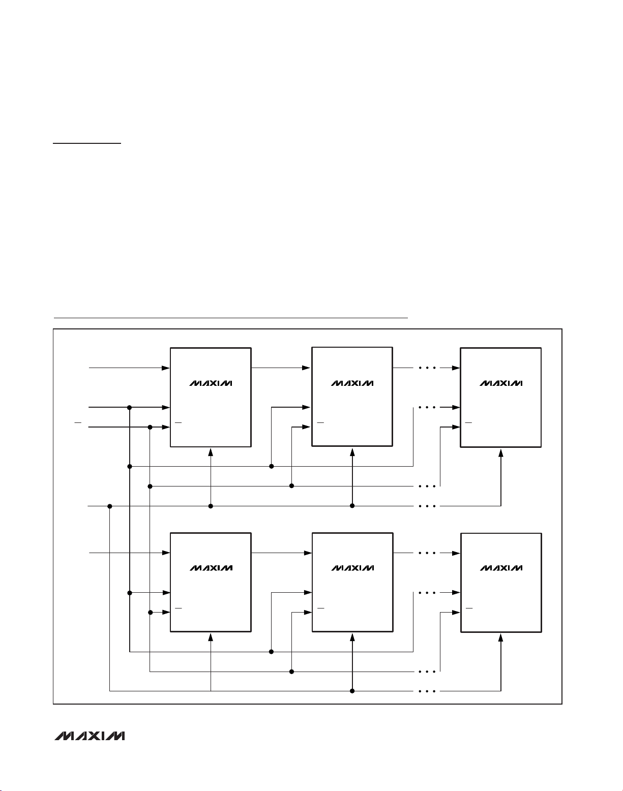
Daisy-Chaining Multiple Devices
Digital output DOUT is provided to allow the connection
of multiple MAX14802/MAX14803/MAX14803A devices
by daisy-chaining (Figure 3). Connect each DOUT to the
DIN of the subsequent device in the chain. Connect CLK,
LE, and CLR inputs of all devices, and drive LE logic-low
to update all devices simultaneously. Drive CLR high to
open all the switches simultaneously. Additional shift registers can be included anywhere in series with the
MAX14802/MAX14803/MAX14803A data chain.
Supply Sequencing and Bypassing
The MAX14802/MAX14803/MAX14803A do not require
special sequencing of the VDD, VPP, and VNNsupply
voltages; however, analog switch inputs must be
unconnected, or satisfy VNN≤ (V
COM_
, V
NO_
) ≤ V
PP
during power-up and power-down. Bypass VDD, VPP,
and VNNto GND with a 0.1µF ceramic capacitor as
close as possible to the device.
Application Diagrams
MAX14802
MAX14803
MAX14803A
MAX14802
MAX14803
MAX14803A
MAX14802
MAX14803
MAX14803A
MAX14802
MAX14803
MAX14803A
MAX14802
MAX14803
MAX14803A
MAX14802
MAX14803
MAX14803A
CLK
DIN
CLK
LE
CLR
U10
U11
U1n
U20
U21
U2n
DOUT
DIN1
LE
CLR
DIN2
DIN
CLK
LE
CLR
DOUT
DIN
CLK
LE
CLR
DOUT
DIN
CLK
LE
CLR
DOUT
DIN
CLK
LE
CLR
DOUT
DIN
CLK
LE
CLR
DOUT
Figure 3. Interfacing Multiple Devices by Daisy-Chaining

MAX14802/MAX14803/MAX14803A
Low-Charge Injection, 16-Channel,
High-Voltage Analog Switches
14 ______________________________________________________________________________________
Figure 4. Medical Ultrasound Application—High-Voltage Analog Switches in Probe
HIGH-VOLTAGE TRANSMIT
1 PER CHANNEL
±100V MAX
LOW-VOLTAGE RECEIVE
64 TO 128 CHANNELS
±1V MAX
+V
10mA TYP
HIGHVOLTAGE
ISOLATION
MAINFRAME
PROBE SELECTION
2 TO 4 PROBES
RELAY
1 RELAY/CH/PROBE
PROBE
A
PROBE
B
PROBE
C
CABLE
1 PER CHANNEL
±1 TO 2A MAX
PROBES
TRANSDUCERS
2 TO 4 PER CHANNEL
HV ANALOG
SWITCHES
2 TO 4 PER CHANNEL
-V
PROBE
D

MAX14802/MAX14803/MAX14803A
Low-Charge Injection, 16-Channel,
High-Voltage Analog Switches
______________________________________________________________________________________ 15
Figure 5. Medical Ultrasound Application—High-Voltage Analog Switches in Mainframe
HV TRANSMIT
1 PER CHANNEL
LV RECEIVE
64 TO 128 CHANNELS
±100V MAX
±1V MAX
+V
-V
10mA TYP
HIGHVOLTAGE
ISOLATION
MAINFRAME
HV ANALOG
SWITCHES
2 TO 4 PER CHANNEL
PROBE SELECTION
2 TO 4 PROBES
RELAYS
2 TO 4 RELAYS/CH/PROBE
CABLE
2 TO 4 PER CHANNEL
±1 TO 2A MAX
PROBE
A
PROBE
B
PROBE
C
PROBES
TRANSDUCERS
2 TO 4 PER CHANNEL
PROBE
D
MAX14802/MAX14803/MAX14803A
Low-Charge Injection, 16-Channel,
High-Voltage Analog Switches
16 ______________________________________________________________________________________
Figure 6. Medical Ultrasound Application—Multiple Transmit and Isolation per Receiver Channel
MAINFRAME
HIGH-VOLTAGE TRANSMIT
2 TO 4 PER CHANNEL
±100V MAX
LOW-VOLTAGE RECEIVE
64 TO 128 CHANNELS
±1V MAX
+V
-V
+V
-V
+V
-V
+V
-V
+V
-V
10mA TYP
PROBE SELECTION
2 TO 4 PROBES
RELAYS
2 TO 4 RELAYS/CH/PROBE
CABLE
2 TO 4 PER CHANNEL
±1 TO 2A MAX
PROBE
A
PROBE
B
PROBE
C
PROBES
TRANSDUCERS
2 TO 4 PER CHANNEL
+V
-V
+V
-V
+V
-V
HIGH-VOLTAGE
ISOLATION AND
CHANNEL SELECT
2 TO 4 PER CHANNEL
PROBE
D

MAX14802/MAX14803/MAX14803A
Low-Charge Injection, 16-Channel,
High-Voltage Analog Switches
______________________________________________________________________________________ 17
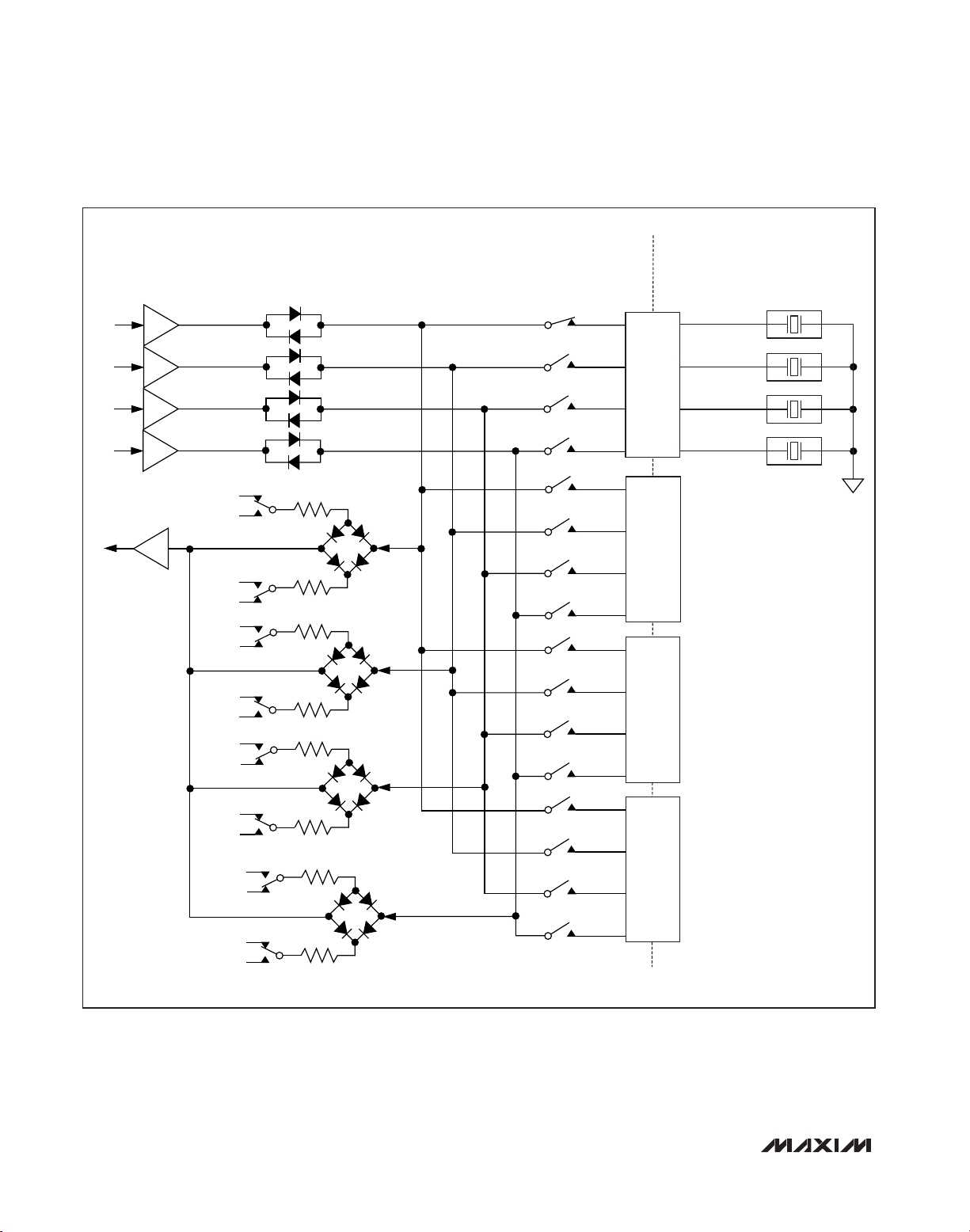
Functional Diagram
CLR
DIN
CLK
DOUT
V
DD
LATCH
16-BIT
SHIFT
REGISTER
LATCH
LE
MAX14802
MAX14803
MAX14803A
V
PP
LEVEL
SHIFTER
LEVEL
SHIFTER
V
PP
COM0
*
V
*
NN
V
NN
V
PP
NO0
COM15
*
V
NN
NO15
*
V
NN
GND V
*BLEED RESISTORS AVAILABLE ON THE MAX14803/MAX14803A ONLY.
NN

MAX14802/MAX14803/MAX14803A
Low-Charge Injection, 16-Channel,
High-Voltage Analog Switches
18 ______________________________________________________________________________________
Pin Configurations
TOP VIEW
COM10
NO10
COM9
NO9
COM8
NO8
NO7
COM7
NO6
COM6
NO5
COM5
N.C.
COM11
N.C.
35
34 33 32 31 30 29 28 27
36
37
38
39
40
41
42
43
44
45
46
47
48
+
2
3456789101112
1
N.C.
N.C.
COM4
NO11
NO4
COM12
NO12
MAX14802
MAX14803
NO3
COM3
NO13
NO2
COM13
COM2
COM14
COM1
NO14
NO1
26
NO15
NO0
25
COM15
COM0
N.C.
24
DOUT
23
22
CLR
21
LE
CLK
20
DIN
19
18
V
DD
17
GND
16
N.C.
V
15
PP
N.C.
14
13
V
NN
TQFP
(7mm x 7mm)

MAX14802/MAX14803/MAX14803A
Low-Charge Injection, 16-Channel,
High-Voltage Analog Switches
______________________________________________________________________________________ 19
Chip Information
PROCESS: BiCMOS
Pin Configurations (continued)
PACKAGE
TYPE
PACKAGE
CODE
OUTLINE
NO.
LAND
PATTERN NO.
48 TQFP C48+6
21-0054 90-0093
110 WLP W1105B5+1
21-0494
Refer to
Application
Note 1891
Package Information
For the latest package outline information and land patterns,
go to www.maxim-ic.com/packages
. Note that a “+”, “#”, or
“-” in the package code indicates RoHS status only. Package
drawings may show a different suffix character, but the drawing
pertains to the package regardless of RoHS status.
TOP VIEW
(BUMPS ON BOTTOM)
+
A
B
C
D
E
F
G
H
J
K
1
N.C.
N.C.
N.C.
NO1
N.C.
COM3
N.C.
NO4
N.C.
N.C.
MAX14803A
234567891011
V
N.C.
V
N.C.
CLK
DOUT
N.C.
N.C.
V
PP
N.C.
NO0
N.C.
COM2
N.C.
NO2
N.C.
COM4
N.C.
N.C.
N.C.
COM1
N.C.
NO3
N.C.
COM5
N.C.
NO5
NN
N.C.
COM0
N.C.
N.C.
N.C.
NO6
N.C.
COM6
N.C.
N.C.
N.C.
N.C.
N.C.
N.C.
N.C.
COM7
N.C.
NO7
GND
N.C.
N.C.
N.C.
N.C.
N.C.
N.C.
N.C.
N.C.
DIN
N.C.
N.C.
N.C.
N.C.
N.C.
COM8
N.C.
NO8
LE
COM15
N.C.
N.C.
N.C.
NO9
N.C.
COM9
N.C.
CLR
N.C.
COM14
N.C.
NO12
N.C.
COM10
N.C.
NO10
COM13
COM11
DD
N.C.
NO15
N.C.
N.C.
NO13
N.C.
N.C.
N.C.
N.C.
N.C.
NO14
N.C.
COM12
N.C.
NO11
N.C.
N.C.
0.31 mm
0.5 mm
(5.81mm x 5.43mm)
WLP
0.5 mm

MAX14802/MAX14803/MAX14803A
Low-Charge Injection, 16-Channel,
High-Voltage Analog Switches
Maxim cannot assume responsibility for use of any circuitry other than circuitry entirely embodied in a Maxim product. No circuit patent licenses are
implied. Maxim reserves the right to change the circuitry and specifications without notice at any time.
20
____________________Maxim Integrated Products, 120 San Gabriel Drive, Sunnyvale, CA 94086 408-737-7600
© 2011 Maxim Integrated Products Maxim is a registered trademark of Maxim Integrated Products, Inc.
Revision History
REVISION
NUMBER
0 4/09 Init ial release —
1 9/09
2 11/10
3 8/11 Added extended temperature information; added MAX14802ECM+ to data sheet 1
REVISION
DATE
DESCRIPTION
Corrected two specifications in the Absolute Maximum Ratings section,
changed the minimum of the peak-to-peak analog signal range to “either VNN + 200V
– 10V)”
or (V
PP
Deleted the MAX14800/MAX14801 from the entire data sheet and added the
MAX14803A; added the WLP part to the Ordering Information, Pin Configurations, Pin
Descriptions, and Package Information sections
PAGES
CHANGED
2, 9
1–19
 Loading...