

Maipu MyPower VG2000 Installation Manual

MyPower VG2000 V4 VoIP
Gateway Installation Manual
Maipu Communication Technology Co., Ltd
No. 16, Jiuxing Avenue
Hi-tech Park
Chengdu, Sichuan Province
People’s Republic of China - 610041
Tel: (86) 28-85148850, 85148041
Fax: (86) 28-85148948, 85148139
URL: http: // www.maipu.com
Email: overseas@maipu.com

MyPower VG2000 V4 VoIP Gateway Installation Manual
Page 1 / 72
Copyright ©2015, Maipu Communication Technology Co., Ltd.
All Rights Reserved.
No part of this manual may be reproduced or transmitted in any
form or by any means without prior written consent of Maipu
Communication Technology Co., Ltd.
All rights reserved.

MyPower VG2000 V4 VoIP Gateway Installation Manual
Page 2 / 72
Preface
Purpose
This manual aims to help users better know and use the
MyPower VG2000 series VoIP gateway. This manual does not
contain all details of MyPower VG2000 series VoIP gateway. It
detailedly describes how to install MyPower VG 2000 series VoIP
gateway.
Audience
This documentation is intended for:
Network engineers
Technical marketing personnel
Network administrator
Introduction
This manual mainly introduces the hardware features,
installation and wiring, and indicators on the panel. To avoid
device damage and human injury during the VoIP gateway
installation, please carefully read this manual.
Conventions
Bold text represents commands and keywords
Italic text represents arguments
Braces "{ }"enclose items that are mandatory.

MyPower VG2000 V4 VoIP Gateway Installation Manual
Page 3 / 72
Square brackets "[ ]"enclose items that are optional.
Caution: an alert that calls attention to important
information and is the installation and security key points.
Note: an alert that contains additional or supplementary
information to the preceding content.
Illustration: text explanation to the preceding figure.
Statement
The information in this document is subject to change without
notice. Every effort has been made in the preparation of this
document to ensure accuracy of the contents, but all
statements, information, and recommendations in this
document do not constitute the warranty of any kind, express or
implied.
Environmental Protection
This product has been designed to comply with the
environmental protection requirements. The storage, use, and
disposal of this product must meet the applicable national laws
and regulations

MyPower VG2000 V4 VoIP Gateway Installation Manual
Page 4 / 72
Contents
1. Installation Preparation................................................... 7
1.1 Environment Requirements..................................................................7
1.1.1 Running Environment........................................................................ 7
1.1.2 Cleanliness Requirement.................................................................. 8
1.1.3 Anti-static Requirement..................................................................... 8
1.1.4 Anti-interference Requirement
.........................................................9
1.2 Check Device and Accessories
........................................................... 9
1.3 Required Tools and Devices.............................................................. 10
2. VG2000-16 Installation................................................... 11
2.1 Hardware Features.............................................................................. 11
2.1.1 MyPower VG2000-16 Appearance................................................. 11
2.1.2 MyPower VG2000-16 Front Panel Description...........................12
2.1.3 POTS(FXS) Port Description
...........................................................13
2.2 Mechanical Installation
........................................................................13
2.2.1 Cabinet Installation........................................................................... 13
2.2.2 Ground Requirement
........................................................................ 17
2.2.3 Power Connection............................................................................. 18
2.3 Cable Connection................................................................................ 19
2.3.1 Console Cable Connection............................................................. 19
2.3.2 Ethernet Cable Connection.............................................................20
2.3.3 POTS(FXS) Cable Connection
........................................................20
3. VG2000-32S Installation................................................ 21
3.1 Hardware Features
.............................................................................. 21
3.1.1 VG2000-32S Appearance................................................................. 21
3.1.2 VG2000-32S Front Panel Description........................................... 22
3.1.3 POTS(FXS) Port Description...........................................................23
3.2 Mechanical Installation........................................................................23
3.2.1 Cabinet Installation
........................................................................... 23
3.2.2 Ground Requirement
........................................................................ 27
3.2.3 Power Connection............................................................................. 28
3.3 Cable Connection
................................................................................ 29
3.3.1 Console Cable Connection............................................................. 29
3.3.2 Ethernet Cable Connection.............................................................30

MyPower VG2000 V4 VoIP Gateway Installation Manual
Page 5 / 72
3.3.3 POTS(FXS) Cable Connection
........................................................30
4. VG2000-32 Installation................................................... 31
4.1 Hardware Features
.............................................................................. 31
4.1.1 MyPower VG2000-32 Appearance
................................................. 31
4.1.2 MyPower VG2000-32 Front Panel Description...........................32
4.1.3 8FXS Interface Module..................................................................... 33
4.1.4 4S4O Interface Module..................................................................... 34
4.1.5 E1 Interface Module.......................................................................... 36
4.2 Mechanical Installation
........................................................................36
4.2.1 Cabinet Installation........................................................................... 36
4.2.2 Grounding Requirement
.................................................................. 40
4.2.3 Power Connection
............................................................................. 40
4.3 Cable Connection................................................................................ 42
4.3.1 Console Cable Connection............................................................. 42
4.3.2 Ethernet Cable Connection.............................................................43
4.3.3 Module Cable Connection
............................................................... 43
5. VG2000-48S Installation................................................ 46
5.1 Hardware Features
.............................................................................. 46
5.1.1 MyPower VG2000-48S Appearance
.............................................. 46
5.1.2 MyPower VG2000-48S Front Panel............................................... 47
5.1.3 POTS(FXS) Port Description...........................................................48
5.2 Mechanical Installation........................................................................48
5.2.1 Cabinet Installation........................................................................... 48
5.2.2 Grounding Requirement
.................................................................. 52
5.2.3 Power Connection............................................................................. 52
5.3 Cable Connection
................................................................................ 54
5.3.1 Console Cable Connection............................................................. 54
5.3.2 Ethernet Cable Connection.............................................................54
5.3.3 POTS(FXS) Cable Connection........................................................55
6. VG2000-64S Installation................................................ 56
6.1 Hardware Features
.............................................................................. 56
6.1.1 VG2000-64S Appearance................................................................. 56
6.1.2 VG2000-64S Front Panel
.................................................................. 57
6.1.3 POTS(FXS) Port Description
...........................................................58
6.2 Mechanical Installation........................................................................58
6.2.1 Cabinet Installation........................................................................... 58

MyPower VG2000 V4 VoIP Gateway Installation Manual
Page 6 / 72
6.2.2 Grounding Requirement
.................................................................. 62
6.2.3 Power Connection
............................................................................. 62
6.3 Cable Connection
................................................................................ 64
6.3.1 Console Cable Connection
............................................................. 64
6.3.2 Ethernet Cable Connection.............................................................65
6.3.3 POTS(FXS) Cable Connection........................................................65
7. Cable Description............................................................ 66
7.1 Ethernet Cable......................................................................................66
7.2 Console Cable
...................................................................................... 69
7.3 FXS/FXO Interface Cable................................................................... 69
8. Security Suggestions..................................................... 71
MyPower VG2000 V4 VoIP Gateway Installation Manual
Page 7 / 72
1.Installation Preparation
1.1 Environment Requirements
1.1.1 Running Environment
To ensure the effective use and stable performance of VG2000
series VoIP gateway, it is recommended to maintain a certain
temperature and humidity in the equipment room. It is good for
protecting the line and extending the VoIP gateway life. The
VG2000 series VoIP gateway must be used indoors.
The VG2000 series VoIP gateway has the requirement for
temperature and humidity as listed in Table 1-1.
Table 1-1 Recommended temperature and humidity in the
equipment room
Temperature
Related Humidity
Long-term
Work
Condition
Short-term
work
Condition
Long-term
Work
Condition
Short-term
Work
Condition
15℃–30
℃
0℃–40
℃
40%–65%
0%–90%

MyPower VG2000 V4 VoIP Gateway Installation Manual
Page 8 / 72
Note
Measuring points of the working temperature and humidity of
theVG2000 series VoIP gateway in the equipment room mean the
values measured 1.5m above the floor and 0.4 m from the front of
the VoIP gateway when there are no protection boards;
The short-term working condition means less than 48h work
continuously and less than accumulative 15-day work in a year.
Extreme severe work environment generally means that
abnormal temperature and humidity may occur when the air
conditioning system of the equipment room is faulty. In this
situation, the gateway should restore to normal work range within
5h.
1.1.2 Cleanliness Requirement
Dust is harmful for the VG2000 series VoIP gateway operation.
Dust causes electrostatic absorption, which makes the poor
contact of metal connectors. Electrostatic absorption appears
especially when the temperature and humidity are lower, which
affects the device life and easily causes communication fault.
1.1.3 Anti-static Requirement
Although VG2000 series VoIP gateway adopts lots of anti-static
measures, it will still cause damage to the circuit and even the
entire device when the static exceeds a certain limit.
In the VG2000 series VoIP gateway communication network,
the electrostatic induction is mainly from two aspects: outside
electric field such as outdoor high voltage transmission line and
lightning and thunder, and interior system such as indoor
environment, floor material, and entire device structure.

MyPower VG2000 V4 VoIP Gateway Installation Manual
Page 9 / 72
Therefore, to prevent static damage, do the following
preparations:
The device is well connected to the ground.
The room must be dustproof.
Keep proper temperature and humidity.
Wear anti-static wrist trap and anti-static overall when the
human touches the circuit board.
1.1.4 Anti-interference Requirement
The various interference sources no matter from the exterior of
devices or application systems or from the interior affect the
devices through capacitance coupling, inductance coupling,
electromagnetic radiation, public impedance (including
grounding system) and lead (such as power lines, signal lines
and output lines). Therefore, pay attention to the following:
Take valid anti-grid disturbance measures for the power
system.
The working ground of the VG2000 series VoIP gateway had
better not be used with the grounding settings of power
devices or anti-lightening grounding settings and the distance
between them had better be as long as possible.
Be away from the strong power radio transmitters, radar
transmitter, and high frequency high-current equipment.
Take electromagnetic shielding methods when necessary.
1.2 Check Device and Accessories
After the installation environment is confirmed to meet the
requirement, you can open the packing box. Before installing
the VoIP gateway, check whether the VG2000 series VoIP

MyPower VG2000 V4 VoIP Gateway Installation Manual
Page 10 / 72
gateway and its accessories are complete by the order.
1.3 Required Tools and Devices
1. Tools
Phillips screwdriver
Level, ruler or tapeline
Gloves and ESD wrist strap.
2. Connected cables
Cables in the package
3. Devices
Configuration terminal (it can be ordinary PC)
Hub or Ethernet switch
Device of optional module (telephone)
MyPower VG2000 V4 VoIP Gateway Installation Manual
Page 11 / 72
2.VG2000-16 Installation
2.1 Hardware Features
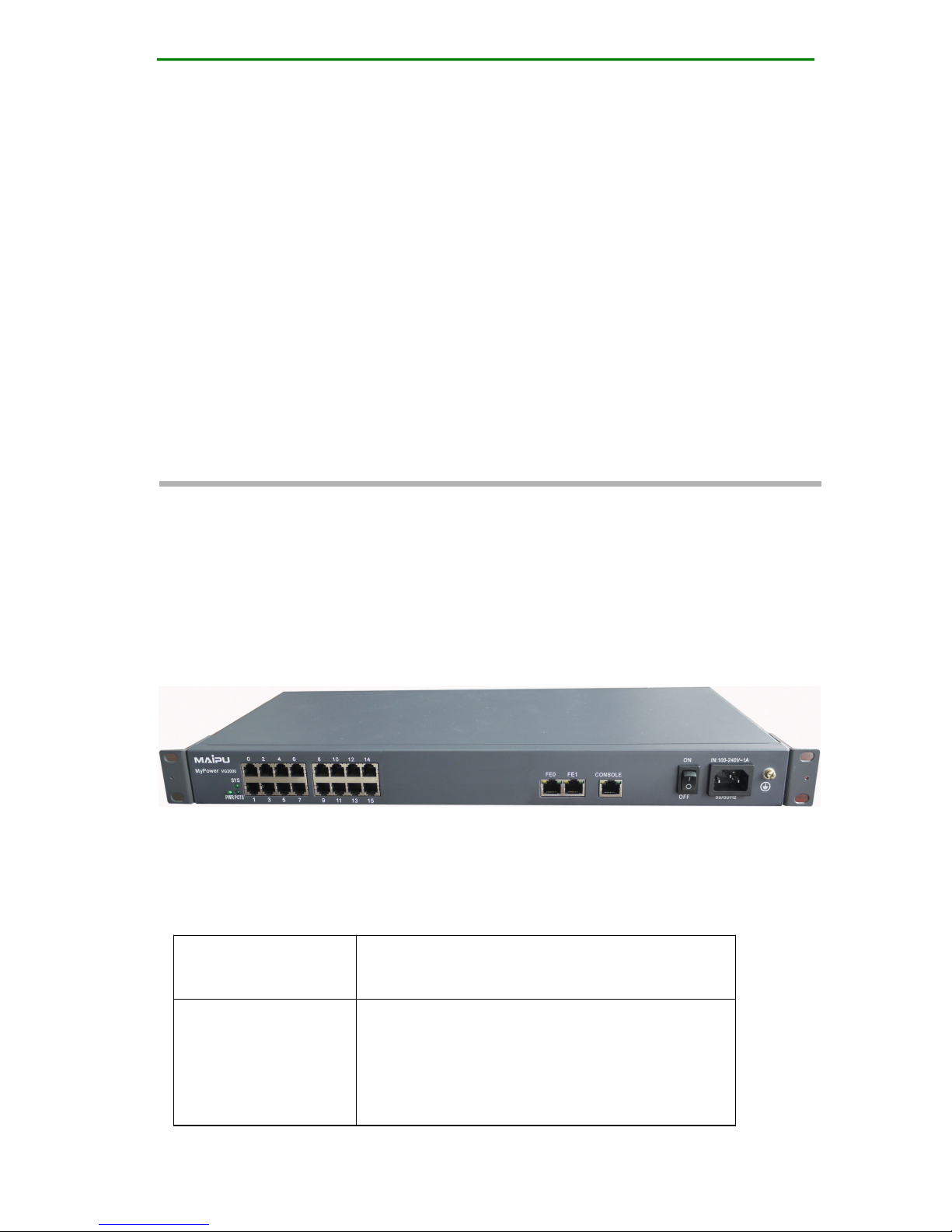
2.1.1 MyPower VG2000-16 Appearance
Figure 2-1 MyPower VG2000-16 appearance diagram
The feature parameters of MyPower VG2000-16 VoIP gateway
are described in the following table.
Storage
FLASH: 16M Bytes
DDR2 SDRAM: 64M Bytes
Fixed
Configuration
One CONSOLE port
Two 10/100M fast Ethernet ports
16 POTS service interfaces (FXS
interface)
MyPower VG2000 V4 VoIP Gateway Installation Manual
Page 12 / 72
Dimension (W
x D x H)
440 mm x 200 mm × 44.5 mm
Work
Temperature
0–40℃
Work Humidity
10–90%, non-condensing
Power
Input AC voltage: 90–265V
Frequency: 50 Hz
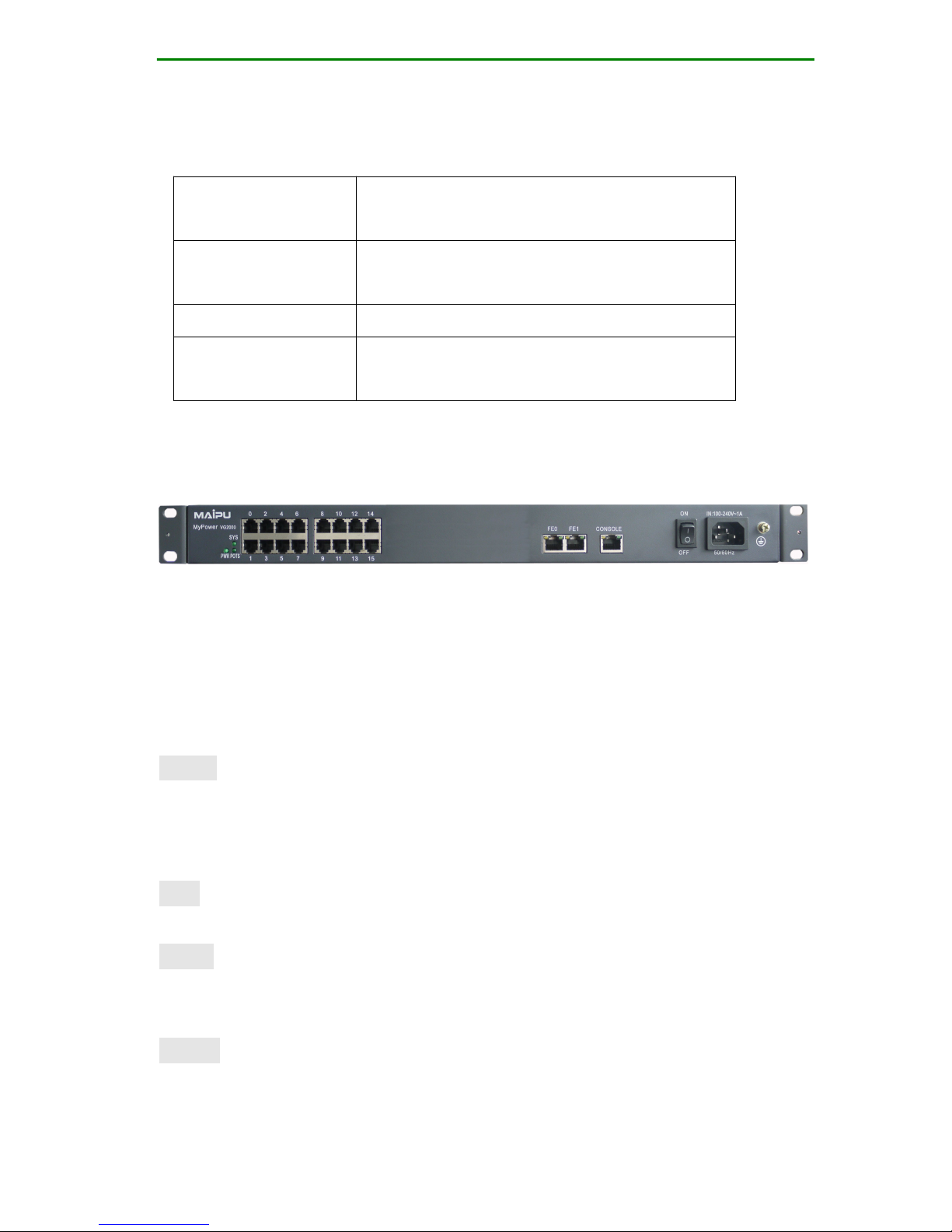
2.1.2 MyPower VG2000-16 Front Panel Description
Figure 2-2 Front panel diagram of MyPower VG2000-16
Figure 2-2 shows the front panel diagram of the MyPower
VG2000-16 VoIP gateway. The indicators on the figure from
left to right respectively are:
PWR
Power indicator: always on state indicates that the power
works normal and other states indicates that the power does
not work or works abnormally.
SYS
The indicator flash indicates normal work.
POTS
Indicator on indicates that any one POTS service interface is in
the off-hook state.
FE0/1
LINK RJ45 left indicator on indicates that the fast Ethernet
link is connected and indicator off indicates that the link is not

MyPower VG2000 V4 VoIP Gateway Installation Manual
Page 13 / 72
connected.
Rx/Tx RJ45 right indicator flash indicates that the fast
Ethernet interface can normal receive and send data.
CONSOLE
Rx CONSOLE port data receiving indicator
Tx CONSOLE port data sending indicator
2.1.3 POTS(FXS) Port Description
0–15: Ports 0–15 are FXS port, which are used to connect
telephone terminal.
2.2 Mechanical Installation
2.2.1 Cabinet Installation
It is recommended to install the MyPower VG2000-16 VoIP
gateway to the 19-inch standard cabinet. When the cabinet is
unavailable, you can place the device horizontally on the clean
plane. Keep at least 10cm space around the device to ensure
enough heat dissipation space. It is recommended to install
the air conditioner in the area with hot summer. The
installation process is as follows:
Step 1: Check the cabinet.
Before installing the device, reserve enough empty slot space
for installing the device.
Use a ruler or tapeline to measure the horizontal installation
hole center distance and horizontal direction installation net
space of the cabinet. The size should comply with the following
figure.

MyPower VG2000 V4 VoIP Gateway Installation Manual
Page 14 / 72
Figure 2-3 Cabinet size
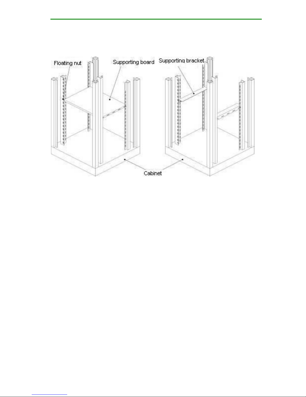
Check whether the supporting board and bracket, floating nut,
fixed screw, and blank panel of the cabinet are complete, which
are standard accessories of the cabinet. The accessory size or
shape varies with different cabinets. Therefore, for the cabinet
accessories, contact the cabinet supplier to provide the original
accessories.
The device must be installed on the supporting board or
supporting bracket (using in pair) of the cabinet. Therefore,
install the supporting board or supporting bracket in the
cabinet in advance before insatlling the device, as shown in the
following figure. User a level to check whether the supporting
board or supporting bracket is horizontal. If not, please adjust
the fixed bolt of the supporting board or supporting bracket to
make them horizontal and then tighten the bolt.
MyPower VG2000 V4 VoIP Gateway Installation Manual
Page 15 / 72
Figure 2-4 Cabinet diagram
Check whether the floating nut of the fixed device is already
installed in the square hole of the cabinet upright post. If not,
install the floating nut to the corresponding square hole based
on the supporting board or supporting bracket location.
Generally, a device should be placed on a supporting board or
supporting bracket. It is not recommended to place multiple
devices overlap each other.
Step 2: Install the MyPower VG2000-16 VoIP gateway to the
cabinet. The diagram is as follows:
MyPower VG2000 V4 VoIP Gateway Installation Manual
Page 16 / 72
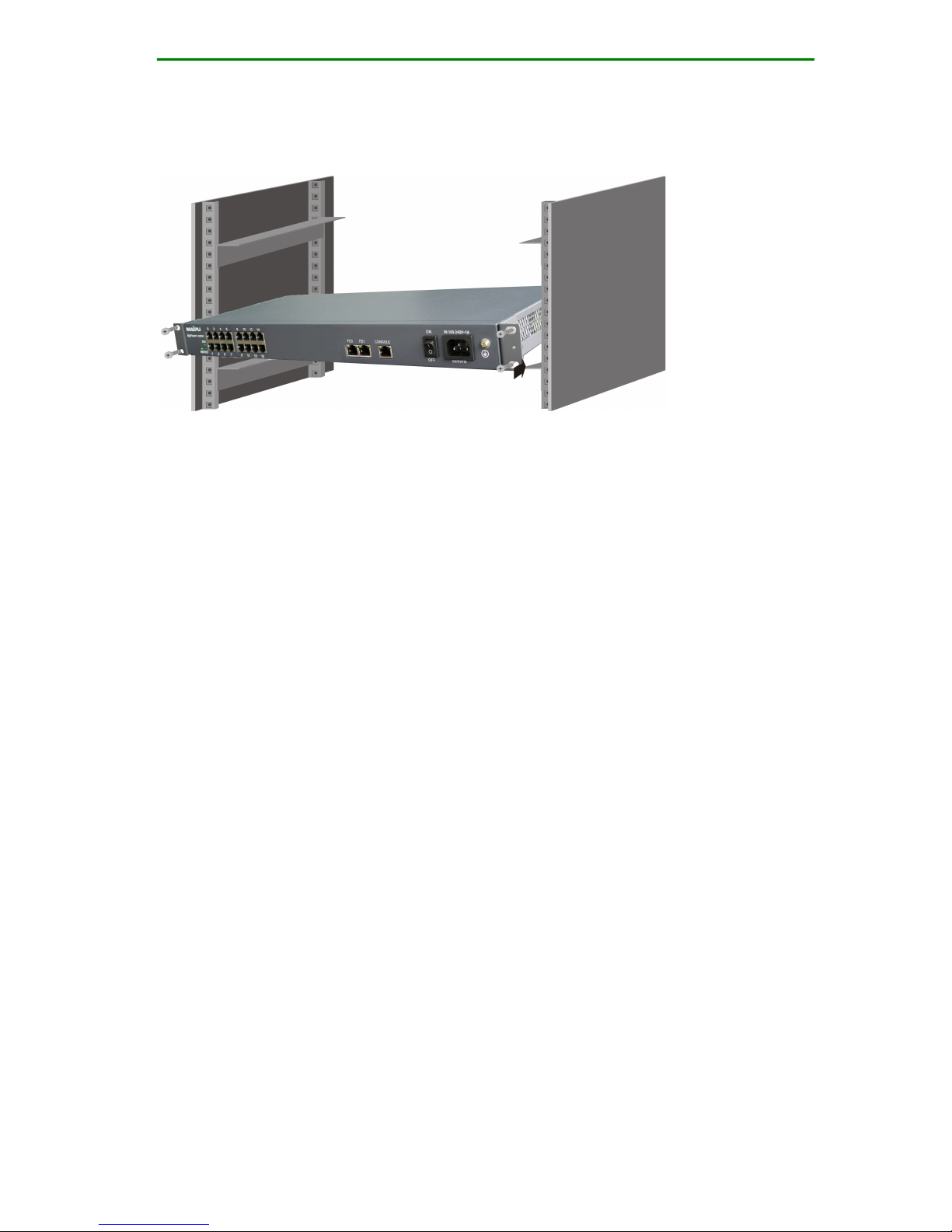
Figure 2-5 Diagram of installing MyPower VG2000-16 VoIP
gateway to the cabinet
1. Wear the glove and ESD wrist strap and connect the ESD
wrist strap to the ground reliably.
2. Place the device on a fixed platform horizontally. Aim the
supporting bracket installation hole to the corresponding
hole on the device side and fix the supporting brackets to the
both two sides of the device using screws.
3. The front side of the device faces the handler. Use hands to
stably hold the device and keep the device horizontally.
Carefully place the device on the supporting bracket or
supporting board from the front side of the cabinet. Please
avoid the device and cabinet upright post collision during
placing.
4. Push the device using two hands and keep the supporting
bracket of the device closely attached to the cabinet upright
post surface.
5. Use a fixed screw to install the device on the upright post of
the device.
6. Check whether the device is installed tightly and straightly.
7. Check the space between the installed devices. Choose an
appropriate blank panel (standard cabinet accessory) and

MyPower VG2000 V4 VoIP Gateway Installation Manual
Page 17 / 72
place it in the space between two devices. Use a screw to fix
the blank panel on the cabinet.
Caution:
Installation suggestions:
When installing multiple devices on the same cabinet, install the
heavy devices at or near the bottom of the cabinet without
affecting the entire wiring and deployment. This can reduce the
cabinet center of gravity to improve stability.
When installing the device in the cabinet, it is recommended to
keep 1U space between two devices to ensure the heat
dissipation space for the device. Install the blank panel
configured for the cabinet in the space between two devices.
2.2.2 Ground Requirement
The ground requirements for the upper bracket and device
with ground pole are as follows:
The ground mode should be in accordance with the joint
ground mode of the work ground, protection ground, and
building lightning protection ground sharing the same ground
body.
Ground line sectional area: ground line (sectional area is
determined by the possible passing maximum current load.
The ground line should adopt the good conductor (copper) lead
and cannot be deployed by the naked lead. The resistance of
the joint ground should be less than 5Ω.)
MyPower VG2000 V4 VoIP Gateway Installation Manual
Page 18 / 72
2.2.3 Power Connection
MyPower VG2000-16 VoIP gateway adopts stable power
system. It has a low requirement for the input AC power.
Domestically, the AC standard for civil use is 220V and 50Hz.
The AC power supply quality may vary in different districts. But
the MyPower VG2000-16 VoIP gateway has a large tolerance
for the input power.
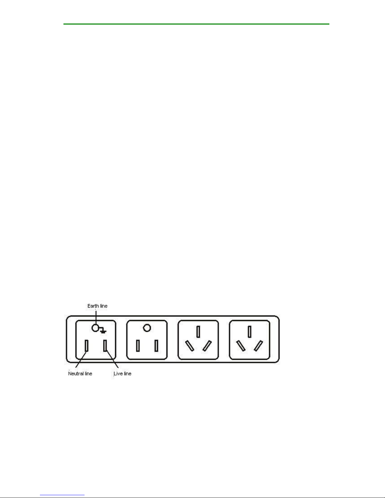
The following power socket or multi-functional microcomputer
power socket is recommended. The earth line of the power
must be grounded well. Generally, when laying out the cables,
the earth line of the building power supply system is already
buried underground. The user should check whether the
building power is grounded reliably. Otherwise, the user should
do corresponding processing.
The following figure shows the shapes of common power
sockets.
Figure 2-6 Common power sockets
Connect the power by the following steps:
Step 1: After the MyPower VG2000-16 VoIP gateway power
switch is placed at the OFF location, connect one end of the

MyPower VG2000 V4 VoIP Gateway Installation Manual
Page 19 / 72
power cable to the power input port of the back panel of the
MyPower VG2000-16 VoIP gateway and insert the other end of
the power cable to the power socket (AC power: 220V
50Hz/60Hz).
Step 2: Tune the power switch of the MyPower VG2000-16
VoIP gateway to the ON location.
Step 3: Check whether the power indicator on the front panel
of the MyPower VG2000-16 VoIP gateway is on. If not, repeat
setpe1 to step 2.
Note
If the power indicator is still off after repeating the preceding
steps, contact the agent.
2.3 Cable Connection
2.3.1 Console Cable Connection
Console cable model: C1223-1032. Connect the cable by the
following steps:
Step 1: Prepare a PC or compatible PC with standard RS-232
serial port.
Step 2: When either MyPower VG2000-16 VoIP gateway or PC
is power-down, connect the console cable respectively to the
RS-232 serial port of the PC and the console port of the
MyPower VG2000-16 VoIP gateway.
Note
The default configuration of MyPower VG2000-16 VoIP gateway:
baud rate 9600, 8 bit data, no parity check, 1 stop bit, no flow

MyPower VG2000 V4 VoIP Gateway Installation Manual
Page 20 / 72
control. Check the identifier on the interface to avoid inserting
incorrectly to other interfaces.
2.3.2 Ethernet Cable Connection
Ethernet cable model: C1212-1002. Connect the Ethernet
interface by the following steps:
Step 1: Insert the one end of the Ethernet cable to FE0 or FE1
Ethernet interface.
Step 2: Connect the other end of the Ethernet cable to the HUB,
switch, PC or other network devices.
Note
Check the identifier on the interface during connection to avoid
module or VG2000-16 VoIP gateway host damage by inserting
other interfaces. Check the host panel indicator state when the
system enters the normal work state. The LINK indicator on
indicates that the link is connected and indicator off indicates
that the link is not connected and check the line in this situation.
2.3.3 POTS(FXS) Cable Connection
Insert one end of the RJ11 cable to the corresponding interface
of the device and the other end to the telephone terminal.
MyPower VG2000 V4 VoIP Gateway Installation Manual
Page 21 / 72
3.VG2000-32S Installation
3.1 Hardware Features
3.1.1 VG2000-32S Appearance
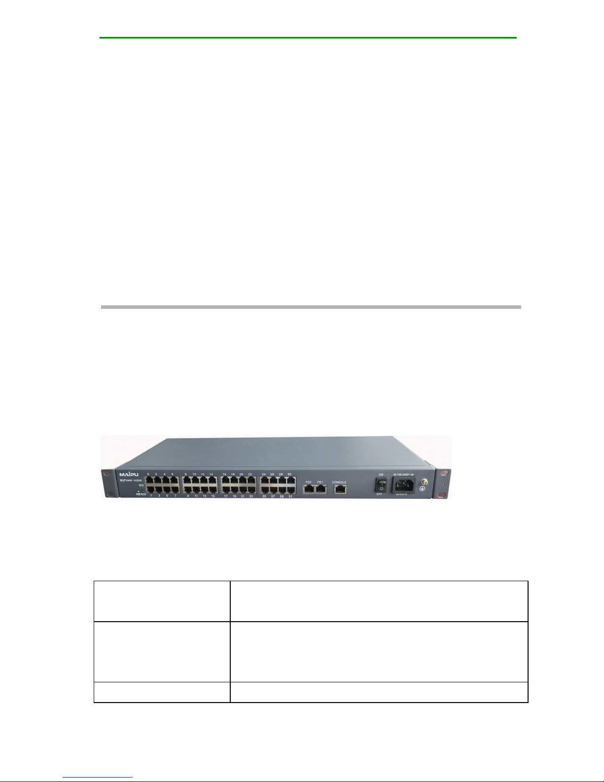
Figure 3-1 VG2000-32S appearance diagram
The feature parameters of MyPower VG2000-32S VoIP
gateway are described in the following table.
Storage
FLASH: 16M Bytes
DDR2 SDRAM: 64M Bytes
Fixed
Configuration
One CONSOLE port
Two 10/100M fast Ethernet ports (FE0,FE1)
32 service ports (FXS interface)
Dimension (W x D
440 mm x 200 mm x 44.5 mm
 Loading...