

Maipu MP2900-04-AC, MP2900-24-AC, MP2900-14-AC, MP2900-24-DC48 Installation Manual

Maipu Confidential & Proprietary Information Page 1 of 80
MP2900 Series Router
Installation Manual
V1.0
Maipu Communication Technology Co., Ltd
No. 16, Jiuxing Avenue
Hi-tech Park
Chengdu, Sichuan Province
People’s Republic of China - 610041
Tel: (86) 28-85148850, 85148041
Fax: (86) 28-85148948, 85148139
URL: http: // www.maipu.com
Email: overseas@maipu.com
MyPower S4220 & S4320 Series Switch Installat ion Manual V1.0
Maipu Confidential & Proprietary Information Page 2 of 80
Preface
Manual Introduction
This manual first describes the appearance , hardware structure, and board c ards of MP2900
series router; sec ondly, describes t he installation preparations of MP2900 series rout er and
how to install it to the c abinet ; at last, describes the basic using methods and daily
maintenanc e of MP2900 series router from the aspects of powering on and running the router,
troubleshooting and dev ice maintenance.
Product Versions
The corresponding product versions of the manual are as follows:
Product Name
Product Version
MP2900-04-AC
V1
MP2900-14-AC
V1
MP2900-24-AC
V1
MP2900-24-DC48
V1
Audience
This docu mentation is intended for:
Hardware installation engineers
Commissioning engineers
Field maintenance engineers
System maintenance engineers
Conventions
Conventions of sc reen output format:
Format
Description
Screen print
Represents the output information of the screen
Keywords of Screen print
The red part represents the key information in the
screen output
MyPower S4220 & S4320 Series Switch Installat ion Manual V1.0
Maipu Confidential & Proprietary Information Page 3 of 80
Symbol c onventions:
Format
Description
An alert that contains additional or supplementary information.
An alert that calls attention to important information that if not
understood or followed can result in data loss, data corruption, or
damage to hardware or software.
An alert that calls attention to important information that if not
understood or followed can result in personal injury or router
damage.
Command conventions:
Convention
Description
Boldface
Bold text represents commands and keywords that you enter literally as shown.
Italic
Italic text represents arguments that you replace w ith actual values.
[ ]
Square brackets enclose syntax choices (keywords or arguments) that are optional.
{ x | y | ... }
Braces enclose a set of required syntax choices separa ted by vertical bars, from which
you se lect one.
[ x | y | ... ]
Square brackets enclose a set of optional syntax choices separated by vertical bars,
from which you select one or none.
{ x | y | ... }
*
Asterisk marked braces enclose a set of required syntax choices separated by vertical
bars, from w hich you select at least one.
&<1-n>
The argument or keyword and argument combination before the ampersand (&) sign
can
be entered 1 to n times.
#
A line that starts w ith a pound (#) sign is comments.
Supporting Manuals of Product
The supporting manuals of t he product:
Manual Name
Overview
MP2900 Series Router
Command Manual
Provides the router query and configuration commands.
Obtaining Documentation
You can acc ess the most up- to-date Maipu product doc umentation on the World Wide Web at
www.maipu.c n.
Technical Support
Technical supporting hotline: 400- 886- 8669

MyPower S4220 & S4320 Series Switch Installat ion Manual V1.0
Maipu Confidential & Proprietary Information Page 4 of 80
Fax: ( +8628)85148948
Documentation Feedback
You can feed back your opinions a nd suggestions by:
Email: tec hsupport@ maipu.c o m
Technical hotline: 400-886-8669
We appreciate your c omments.
Rev ision Records
Version
Revision Date
Revised Content
V1.0
2013-04-20
First formal release

MyPower S4220 & S4320 Series Switch Installat ion Manual V1.0
Maipu Confidential & Proprietary Information Page 5 of 80
Contents
Preface ............................................................................................................. 2
1 Router Introduction .................................................................................... 8
1.1 MP2900-04-AC Appearance and Hardware Structure ........................................................8
1.2 MP2900-14-AC Appearance and Hardware Structure ........................................................9
1.3 MP2900-24-AC Appearance and Hardware Structure ..................................................... 10
1.4 MP2900-24-DC48 Appearance and Hardware Structure ................................................ 10
1.5 MP2900 Series Router Panel Specifications ........................................................................ 11
1.6 MP2900 Series Router Air Passage ....................................................................................... 13
2 Installation Preparations .......................................................................... 14
2.1 Check Router Running Environment .................................................................................... 14
2.2 Safety Precautions .................................................................................................................... 14
2.2.1 General Safety ........................................................................................................................14
2.2.2 Electrical Safety ......................................................................................................................15
2.2.3 Static Safety............................................................................................................................15
2.2.4 Laser Safety ............................................................................................................................16
2.3 Installation Tools, Instruments, and Equipment ............................................................... 16
2.4 Open-Package and Inspection ............................................................................................... 17
3 Router Installation .................................................................................... 18
3.1 Install Router.............................................................................................................................. 18
3.1.1 Install Router to Workbench...................................................................................................18
3.1.2 Install Router to Cabinet.........................................................................................................18
3.2 Ground the Router .................................................................................................................... 21
3.3 (Optional) Install Interface Daughter Card Components ................................................ 23
3.3.1 Install USIM Card....................................................................................................................23
3.3.2 Install 3G Antenna ..................................................................................................................25
3.4 (Optional) Install SPD .............................................................................................................. 27
3.4.1 Install AC Power SPD..............................................................................................................27
3.4.2 (Optional) Install POE Surge Protector...................................................................................28
3.5 Connect Power Cable ............................................................................................................... 29
3.5.1 Installation Preparations .........................................................................................................29
3.5.2 Connect AC Power Cable ........................................................................................................29
3.5.3 Connect DC Power Cable........................................................................................................30
3.6 Check after Installation............................................................................................................ 31
4 Power on and Run Router ........................................................................ 32
4.1 Log into Router .......................................................................................................................... 32
4.1.1 Connect Configuration Cable ..................................................................................................32

MyPower S4220 & S4320 Series Switch Installat ion Manual V1.0
Maipu Confidential & Proprietary Information Page 6 of 80
4.1.2 Set PC HyperTerminal Parameters.........................................................................................33
4.1.3 Power on and Start.................................................................................................................35
4.1.4 Check after Power on .............................................................................................................36
4.2 Access Network ......................................................................................................................... 37
4.2.1 Access Network via Ethernet Twisted Pair .............................................................................37
4.2.2 Access Network via Fiber........................................................................................................37
4.3 Hardware Management ........................................................................................................... 40
4.3.1 View Software and Hardware Version Information of Router ...............................................40
4.3.2 View System Environment Temperature Information...........................................................41
4.3.3 View Fan Status Information..................................................................................................41
4.3.4 View Pluggable Optical Module Information...........................................................................42
5 Router Troubleshooting ............................................................................ 43
5.1 Troubleshooting of Configuration System ........................................................................... 43
5.1.1 Troubleshooting about no Display on Terminal .....................................................................43
5.1.2 Troubleshooting about Messy Code on Terminal ...................................................................43
5.2 Troubleshooting about Fan ..................................................................................................... 44
5.3 Troubleshooting about Power ................................................................................................ 44
5.4 Get Technical Support.............................................................................................................. 45
6 Router Maintenance .................................................................................. 46
6.1 Change Interface Daughter Card .......................................................................................... 46
6.2 Change Pluggable Optical Module ......................................................................................... 48
6.3 Dedust the Router..................................................................................................................... 49
6.3.1 Dedust the Fan .......................................................................................................................50
6.3.2 Dedust the Interface Daughter Card......................................................................................50
6.3.3 Dedust the Optical Interface and Pigtail Connector ...............................................................51
Appendix ........................................................................................................ 53
A Entire Router and Common Module Specifications............................................................... 53
A.1 Power Consumption/Dimension/Weight ...................................................................................53
A.2 RM2B Interface Daughter Card Specifications ..........................................................................54
B Specifications of General Interfaces ......................................................................................... 62
B.1 10Base-T/100Base-TX/1000Base-T-RJ45 Electrical Interface Attributes ................................62
B.2 1000Base-X-SFP Optical Interface Attributes ...........................................................................62
B.3 High-speed V.24/V.35 Serial Interface Attributes ....................................................................63
B.4 E1/CE1 Interface Attributes.......................................................................................................63
C Router Running Environment Requirement ........................................................................... 64
C.1 Environment Requirement ........................................................................................................64
C.2 Requirements for Power Supply................................................................................................66
D Router Grounding Specifications and Protection................................................................... 69
D.1 Routing Grounding Specifications .............................................................................................69
D.2 Router Protection.......................................................................................................................72
E Cables .............................................................................................................................................. 75
E.1 Console Cable ............................................................................................................................75
E.2 FE Ethernet Interface Cable.......................................................................................................75
E.3 GE Ethernet Interface Cable ......................................................................................................76

MyPower S4220 & S4320 Series Switch Installat ion Manual V1.0
Maipu Confidential & Proprietary Information Page 7 of 80
E.4 E1/CE1 Interface Cable..............................................................................................................77
E.5 SA Cable.....................................................................................................................................78
F Environmental Substance Statement ...................................................................................... 80
MyPower S4220 & S4320 Series Switch Installat ion Manual V1.0
Maipu Confidential & Proprietary Information Page 8 of 80
1 Router Introduction
MP2900 series routers include the following four p roduc t models: MP2900-04- AC, MP2 900-14AC, MP2900-24-AC, and MP2900-24-DC48.
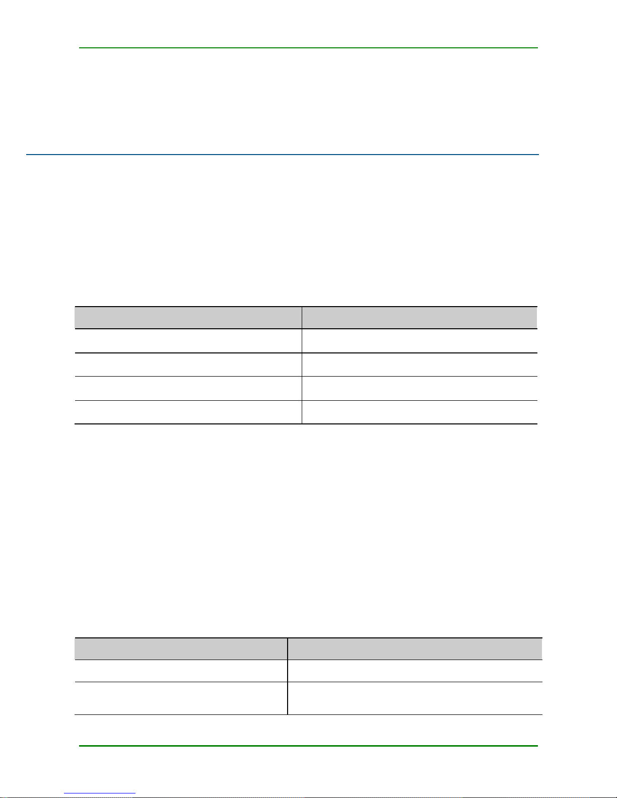
1.1 MP2900-04-AC Appearance and
Hardware Structure
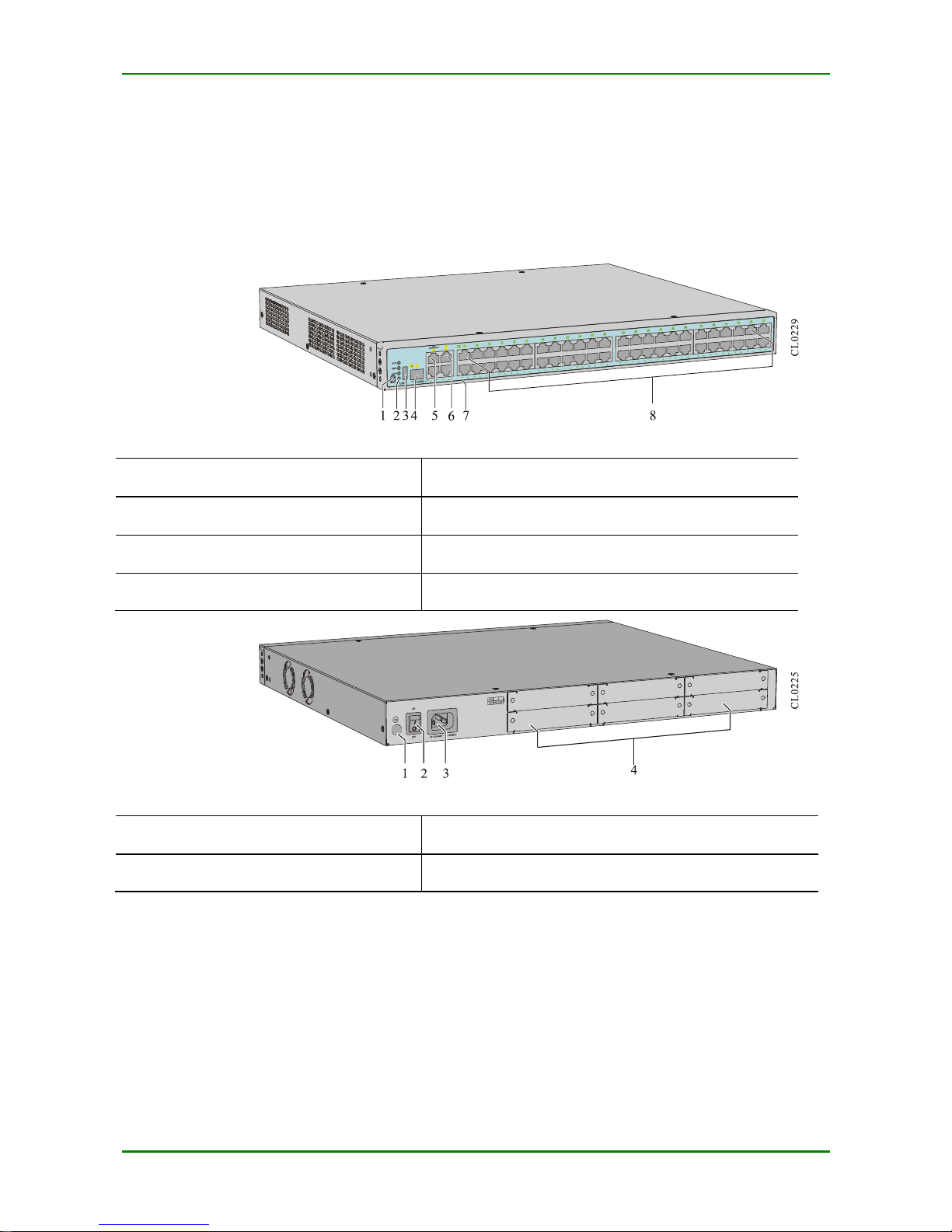
The chassis dimension of MP2900- 04- AC is 442 mm x 3 80 mm x 44.2 mm (W x D x H). The
front panel view of MP2 900- 04- AC is shown in Figure 1- 1 and back panel view of MP2900-04AC is shown in Figure 1-2.
F I G URE 1 - 1 F RO N T P A NE L V I EW O F M P29 0 0 - 04- AC
1.Reset button
2.Function status indicator
3.USB interface
4.1000Base-x SFP Ethernet Combo optical interface
5. Console port
6.Interfce indicator
7.GE interface (GE0 – GE2)
F I G URE 1 - 2 BA CK P A NE L V I E W O F M P2 9 0 0 - 04-AC
1.Ground screw
2.Power switch
3.Power socket
4. RM2B interface daughter card slot (S1 – S4)
MyPower S4220 & S4320 Series Switch Installat ion Manual V1.0
Maipu Confidential & Proprietary Information Page 9 of 80
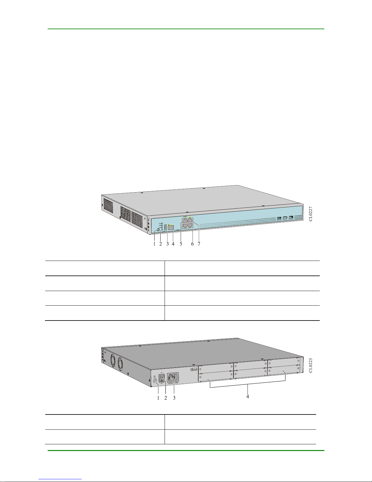
1.2 MP2900-14 -AC Appearance and
Hardware Structure
The chassis dimension of MP2900- 14- AC is 442 mm x 380 mm x 4 4.2 mm (W x D x H). The
front panel view of MP2 900- 14- AC is shown in Figure 1- 3 and back panel view of MP2900- 14AC is shown in Figure 1-4.
F I G URE 1 - 3 F RO N T P A NE L V I EW O F M P29 0 0 - 14- AC
1.Reset button
2.Function status indicator
3.USB interface
4.1000Base-x SFP Ethernet Combo optical interface
5. Console port
6.Interface indicator
7.GE interface (GE0 – GE2)
8.FE interface (FE0 – FE23)
F I G URE 1 - 4 BA CK P A NE L V I E W O F M P2 9 0 0 - 14-AC
1.Ground screw
2.Power switch
3.Power socket
4. RM2B interface daughter card slot (S1 – S4)
MyPower S4220 & S4320 Series Switch Installat ion Manual V1.0
Maipu Confidential & Proprietary Information Page 10 of 80
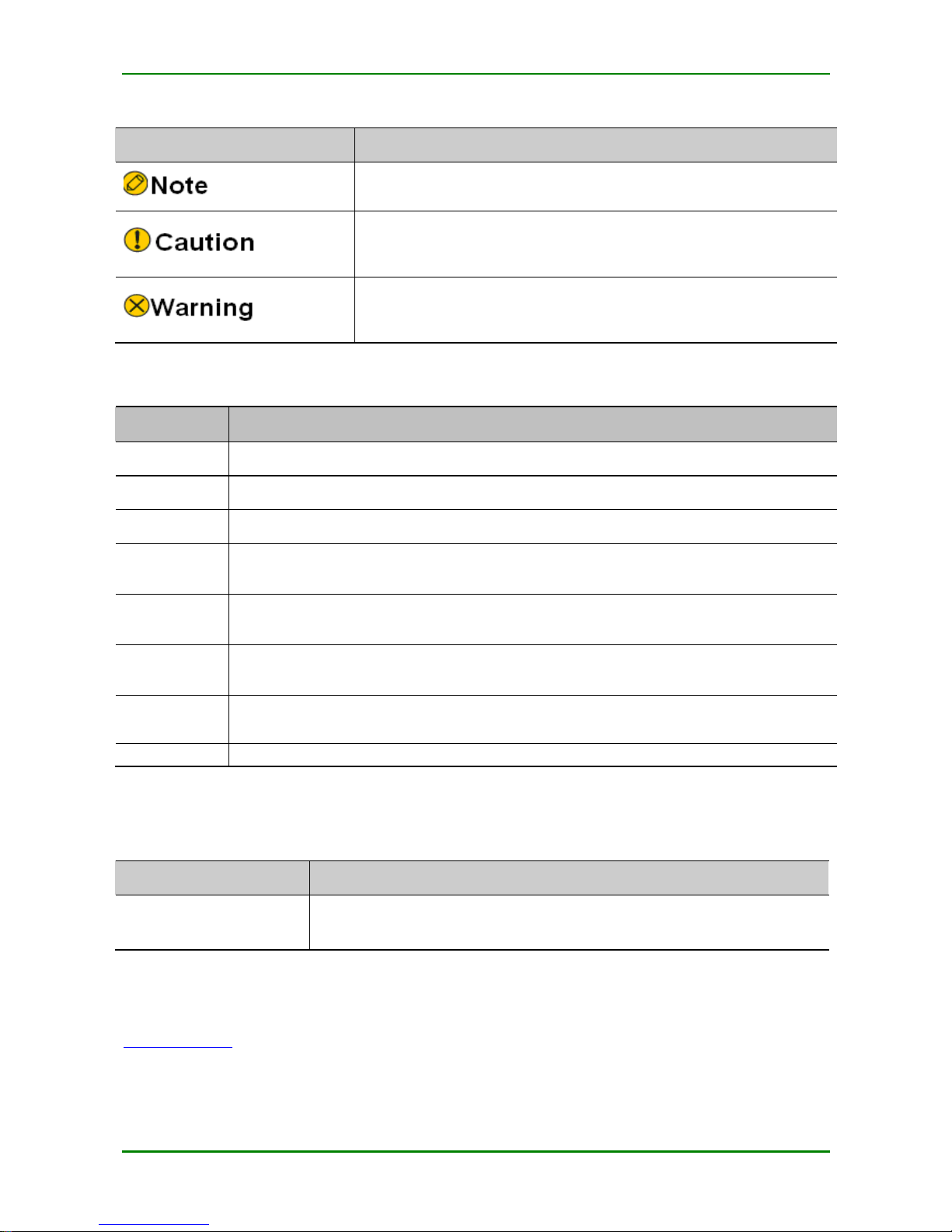
1.3 MP2900-24 -AC Appearance and
Hardware Structure
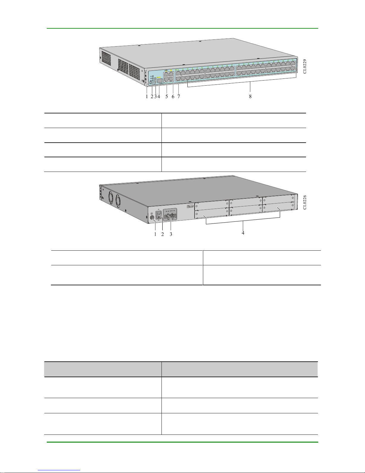
The chassis dimension of MP2900- 24- AC is 442 mm x 380 mm x 44.2 mm (W x D x H). The
front panel view of MP2 900- 24- AC is shown in Figure 1- 5 and the back panel view of MP290024-AC is shown in Figure 1-6.
F I G URE 1 - 5 F RO N T P A NE L V I EW O F M P29 0 0 - 24- AC
1.Reset button
2.Function status indicator
3.USB interface
4.1000Base-x SFP Ethernet Combo optical interface
5.Console port
6. GE interface (GE0 – GE2)
7.Interface indicator
8.FE interface (FE0 – FE47)
F I G URE 1 - 6 BA CK P A NE L V I E W O F M P2 9 0 0 - 24-AC
1.Ground screw
2.Power switch
3.Power socket
4. RM2B interface daughter card slot (S1 – S4)
1.4 MP2900-24 -DC48 Appearance and
Hardware Structure
The chassis dimension of MP2900- 24- DC48 is 442 mm x 380 mm x 44.2 mm (W x D x H). The
front panel view of MP2 900- 24- DC48 is shown in Figure 1-7 and the bac k panel view of
MP2900-24- DC48 is shown in Figure 1- 8.
MyPower S4220 & S4320 Series Switch Installat ion Manual V1.0
Maipu Confidential & Proprietary Information Page 11 of 80
F I G URE 1 - 7 F RO N T P A NE L V I EW O F M P29 0 0 - 24- DC48
1.Reset button
2.Function status indicator
3.USB interface
4.1000Base-x SFP Ethernet Combo optical interface
5.Console port
6.GE interface (GE0 – GE2)
7.Interface indicator
8.FE interface (FE0 – FE47)
F I G URE 1 - 8 BA CK P A NE L V I E W O F M P2 9 0 0 - 24-DC48
1.Ground screw
2.Power switch
3.DC power wiring terminal
4. RM2B interface daughter card slot (S1 –
S4)
1.5 MP2900 Series Router Panel
Specifications
The interfac e description is as follows:
T A BLE 1 - 1 I NT R O DU CTI O N TO TH E F RO NT P A NEL I N T E R F A CES O F T H E M P 2 9 0 0 S ER I ES RO UT E R
Interface Name
Description
Reset button
Presses the button for 3 seconds and the system resets to
the default setting.
USB
One USB interface with the USB2.0 standard
Console
Configuration interface, one RJ-45 connector,
asynchronous serial po rt, default

MyPower S4220 & S4320 Series Switch Installat ion Manual V1.0
Maipu Confidential & Proprietary Information Page 12 of 80
Interface Name
Description
baud rate: 9600 bps
GE0 – GE2 electrical interface
WAN interface, three RJ-45 connectors, 10M/100M/1000M
Ethernet interface , supporting the (MDIX) auto matic
media-dependent interface crosso ver
GE0 optical interface
WAN interface, Combo port, one SFP optical interface,
100M/1000 Mbps full duplex
FE0 – FE47 electrical interface
LAN interface, 48 RJ-45 connectors, 10M/100M Ethernet
interface, supporting the MDIX
MP2900-04-AC: none
MP2900-14-AC: 24 interfaces
MP2900-24-AC: 48 interfaces
MP2900-24-DC48: 48 interfaces
The meanings of the panel indicators are shown in the following table.
T A BLE 1 - 2 MEA NI NG O F TH E P A NEL I N DI C A T O R S
Indicator Name
Indicator Color
Status Description
SYS
Green
Flash: indicates that the router works properly.
Off/On: indicates the router works abnormally.
PWR
Green
Alwa ys on: indicates that the system power status is
normal.
Alwa ys off: indicates the system powe r alarm
FAN
Green
Alwa ys on: indicates that the system fan status is
normal.
USB
Green
Alwa ys on: indicates that the USB device works
prope rly.
Off: indicates that no USB device is insta lled or the
USB device is removed.
Flash: indicates that the USB device is transmitting
data.
CONSOLE
Green
Off: indicates that no data is transmitted over the
port.
Flash: indicates that data is transmitte d over the
port.
GE0 – GE2
Green
Alwa ys on: indicates that the port is up.
Off: indicates that the port is down.
Flash: indicates that data is transmitte d over the
port.

MyPower S4220 & S4320 Series Switch Installat ion Manual V1.0
Maipu Confidential & Proprietary Information Page 13 of 80
Indicator Name
Indicator Color
Status Description
FE0 – FE47
Green
Alwa ys on: indicates that the port is up.
Off: indicates that the port is down.
Flash: indicates that data is transmitte d over the
port.
1.6 MP2900 Series Router Air Passage
The left and right sides of t he MP2900 series router are the air inlet and outlet, as shown in the
following figure.
F I G URE 1 - 3 A I R P A SSA GE O F THE MP 2 9 0 0 SER I E S R O U T ER
Keep t he air passage of the route unblocked during t he operation.
Avoid placing the device with left outlet adjacently above and below the router.
MyPower S4220 & S4320 Series Switch Installat ion Manual V1.0
Maipu Confidential & Proprietary Information Page 14 of 80
2 Installation Preparations
When the router is delive red, there is the pac king list. Please c onfirm whether the
acc essories are c o mplete and good acc ording to the items in the packing list. If there is
damaged or loss, please contact Maipu technical staff to replace.
2.1 Check Router Running
Environment
The MP2900 series routers must be used indoors. T o ensure the normal running of the router,
take the corresponding measures to meet the environment requirement of t he router running:
Air conditioning and ventilation system can ensure the normal running temperature and
humidity conditions of the router. For details, refer to Appendix C1 Appendix C1
Environment Requirement.
The good grounding is the basis of the router running and the important guarantee
conditions of preventing lightning and resisting interference. Ensure that grounding meets
the grounding specificat ions. For details, refer to Appendix D1 Routing Grounding
Specifications.
Ensure that the cleanness of the equipment room meets the requirement. Do not plac e the
router in t he environment with lots of dust, such as in the being renovat ed passage.
2.2 Safety Precautions
2.2.1 General Safety
Keep the router c lean and dust - free; do not place the router in the damp place.
MyPower S4220 & S4320 Series Switch Installat ion Manual V1.0
Maipu Confidential & Proprietary Information Page 15 of 80
2.2.2 Electrical Safety
Please check whet her there are pot ential dangers. For example, the power is not
grounded, power supply g rounding is not reliable, and the ground is wet .
Befo re mov ing the router, be sure to remove all external c ables (including powe r c able).
When maintaining with power, it is recommended t hat t here are two or more persons in
the field.
When closing the power, c hec k and ensure that t he power is t urned off.
2.2.3 Static Safety
To avoid the static from damaging the elect ronic parts of the router, we need t o take the antistatic measures.
When installing the c omponents of the router, espec ially installing the components with
the circuit board (such as board), we should wear anti-static wrists.
When holding the circuit board, p lease hold the edge of the circuit board a nd do not
touch the components or printed c ircuit.
For t he security, please check the resistance of the anti- static wrists. The resistance
between t he body and t he ground should be 1- 10 megohms.
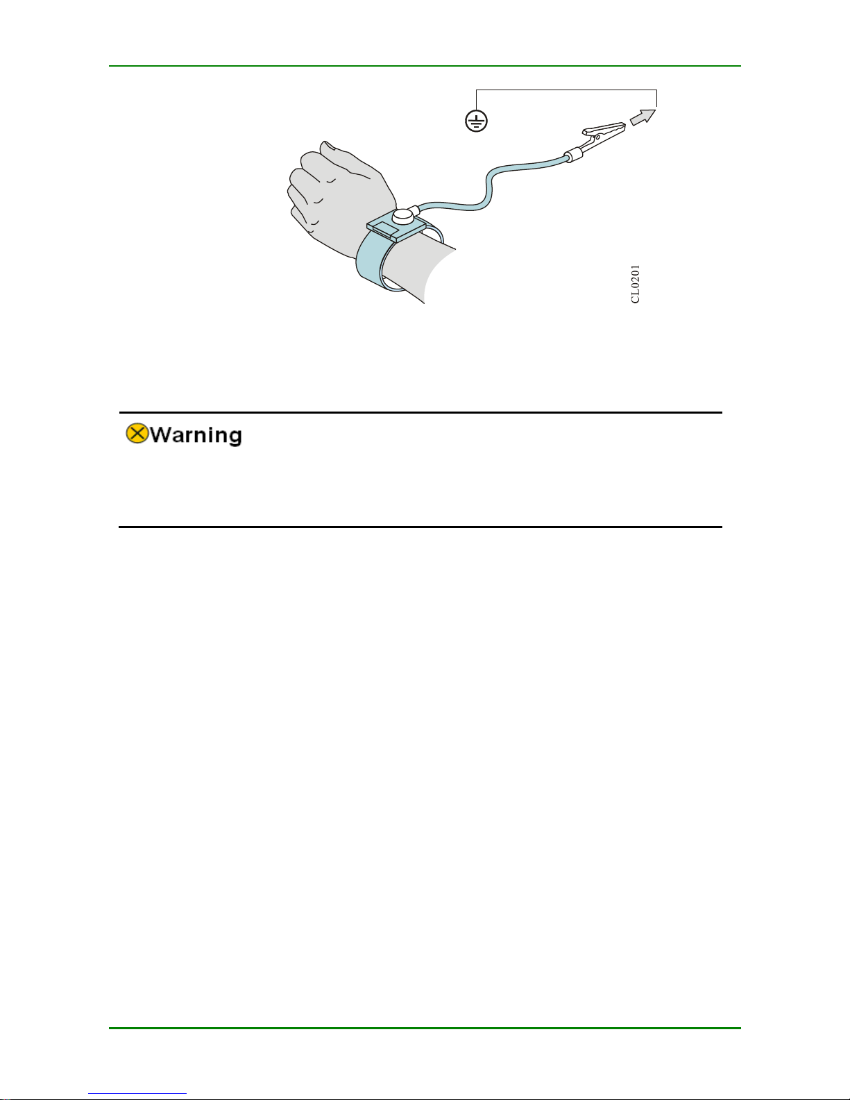
The using steps of the anti-static wrists are as follows:
Step 1:
Put his hand into the anti-static wrist.
Step 2:
Tighten the fastener and ensure that the piece metal on t he anti-static wrist is
well contacted with the skin.
Step 3:
Insert the anti-static wrist into the anti- stat ic wrist jack on the router c hassis or
clip the alligator clip of the anti-static wrist to the grounding terminal of t he
router.
Step 4:
Ensure t hat the anti-static wrist well-grounded. T he using method of the antistatic wrist is shown in the following figure.
MyPower S4220 & S4320 Series Switch Installat ion Manual V1.0
Maipu Confidential & Proprietary Information Page 16 of 80
F I G URE 2 - 1 U S I NG MET HO D O F A NTI - S T A TIC W R I S T
2.2.4 Laser Safety
For the MP2900 series router with the optical interface, avoid direct ly viewing the
laser beam from the optical module inside. View ing the laser bea m from the optical
module inside directly may da mage your eyes.
2.3 Installation Tools, Instruments, and
Equipment
Tools:
Phillips srewdriver
Slotted screwdriver
Anti-static srist
Paper knife
Cables:
PGND c able and power c able
Console c able
Optional c able
Equipment and instruments:
Configurable termianl (a common PC or a laptop)
Multimeter

MyPower S4220 & S4320 Series Switch Installat ion Manual V1.0
Maipu Confidential & Proprietary Information Page 17 of 80
2.4 Open-Package and Inspection
The MP2900 series router adopts the carton packaging. T he package comprises the carton,
plastic bags, protection EPE and other packaging materials. The open- pac kage steps are as
follows:
Step 1:
View the c arton label, and c onfirm the router model in t he carton.
Step 2:
Use a paper knife to gash the tape along the lid c ommissure; be careful when
using the knife and do not insert too deep t o avoid damaging equipment inside.
Step 3:
Open the carton, remove the protection EPE, and then you c an get out of the
router.
MyPower S4220 & S4320 Series Switch Installat ion Manual V1.0
Maipu Confidential & Proprietary Information Page 18 of 80
3 Router Installation
3.1 Install Router
Based on different installation positions, the router can be installed in the follow ing two modes:
Install t he router to the workbench.
Install the router to the cabinet.
3.1.1 Install Router to Workbench
Place the router on the clean workbench. The following ope ration should be paid att ention to
during t he installation:
Ensure the stability and well-grounding of the workbench.
There is 10c m heat dissipation spac e around the router.
Do not place heavy things on the router.
3.1.2 Install Router to Cabinet
This section describes how to install the MP2900 series router to the 19-inch standard cabinet.
Installation Preparations
MP2900 series router is 1U high, so ensure that enough installation space is reserved
for the router.
Check the grounding and stability of the cabinet and ensure that there is no obstacle
inside and around the cabinet affecting the router installation.
1U is 44.45 mm. Here, U is short for Rac k Unit.
Install Slide to Cabinet
The slide supports the router weight. If a slide is already on the c abinet, skip this section.
MyPower S4220 & S4320 Series Switch Installat ion Manual V1.0
Maipu Confidential & Proprietary Information Page 19 of 80
Besides the slide, a t ray also can be used to support the router. The installation process
of the slide is the sa me as that of the tray. Therefore, the tray installation process is
omitt ed in this installation manual.
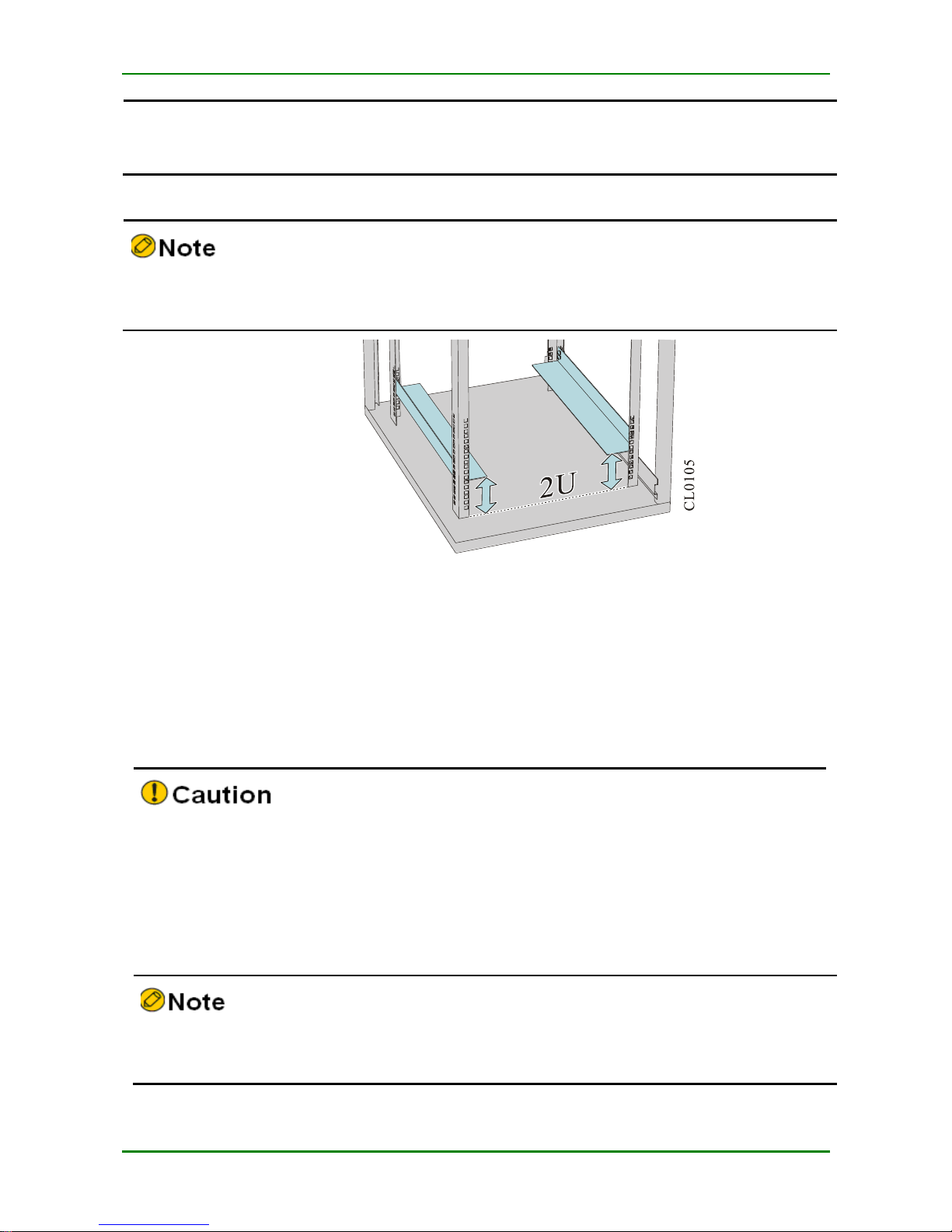
Ensure that the distance between the slid to the bottom cabinet is 2U and three holes on
the square hole bar is 1U, as sown in Figure 3-1.
F I G URE 3 - 1 T HE MI NI MU M S L I DE HEI G H T
The following describes how t o install a slide t o the 19- inch standard cabinet.
The installation steps of t he slide are as follows:
Step 1:
Ensure the installation position of the slide on the c abinet and mark the
installation hole pos ition using a marker.
The space height above the slide must be larger than the to- be-installed router chassis he ight
and enough margin is reserved ( 1U margin is rec ommended).
To ensure t he stability of the c abinet, t ry t o plac e a heavy and high router be low the
cabinet.
Step 2:
Install the slide on the two sides, respectively. The slides installed on the both
sides must be at the same height. Then, t ighten the fixed screw.
The appearance and installation methods of different cabinets and slides may vary. This
section is just for your reference. Goods in kind prevail.
MyPower S4220 & S4320 Series Switch Installat ion Manual V1.0
Maipu Confidential & Proprietary Information Page 20 of 80
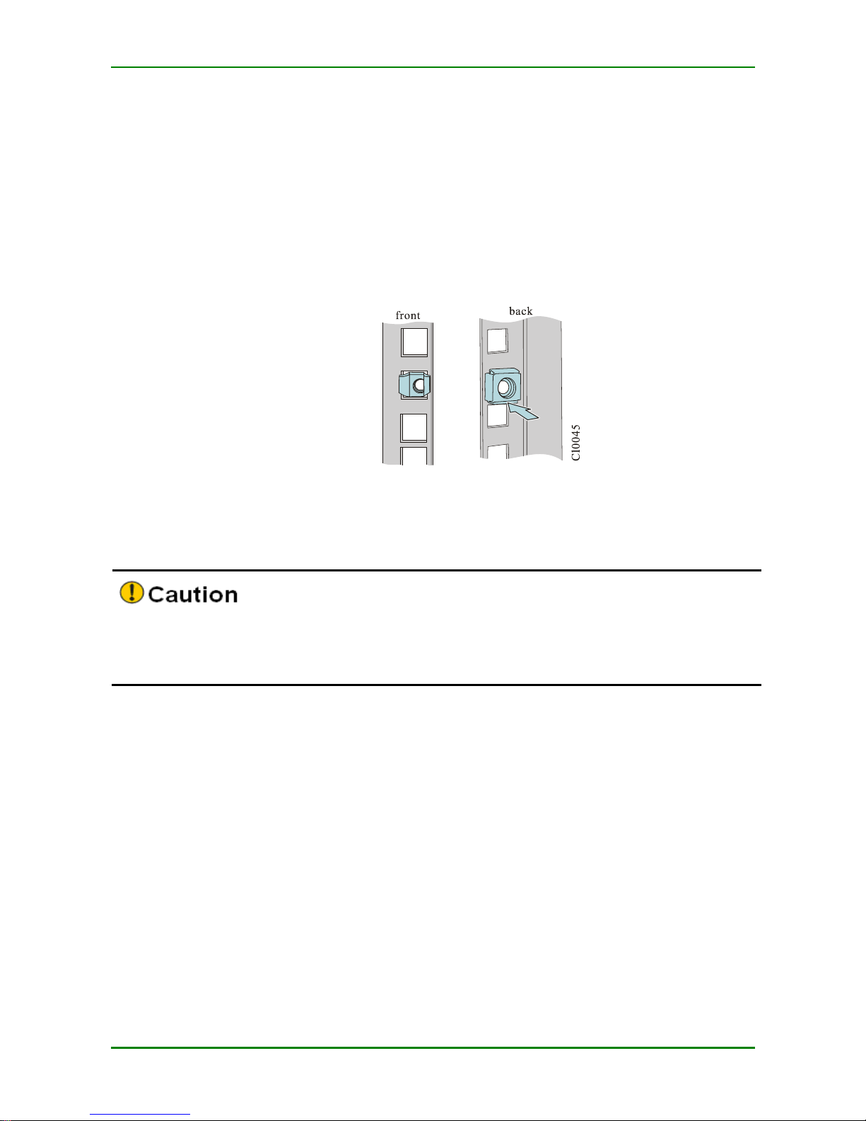
Install Floating Nut to Cabinet
Before installing the c hassis to the cabinet, first install the floating nut on t he upright square
hole bar on the both sides in the front of the cabinet.
Step 1:
Mark the installation pos ition of the floating nut on the upright square hole bar
using a ma rker by c o mparing with t he installation hole position on the router
hanging ears.
Step 2:
Install the floating nuts on the marked positions. A floating nut must be installed
on eac h installation hole on the hanging ear.
F I G URE 3 - 2 I N S TA L L T HE F L O A TI NG N U T
Install Router to Cabinet
Befo re installing the router t o the cabinet, ensure that the corresponding pos itions on the
cabinet are installed with s lide (tray) and the slide (tray) c an support the weight of router
and its acc essories.
The following describes t he installation process of installing the router to t he cabinet.
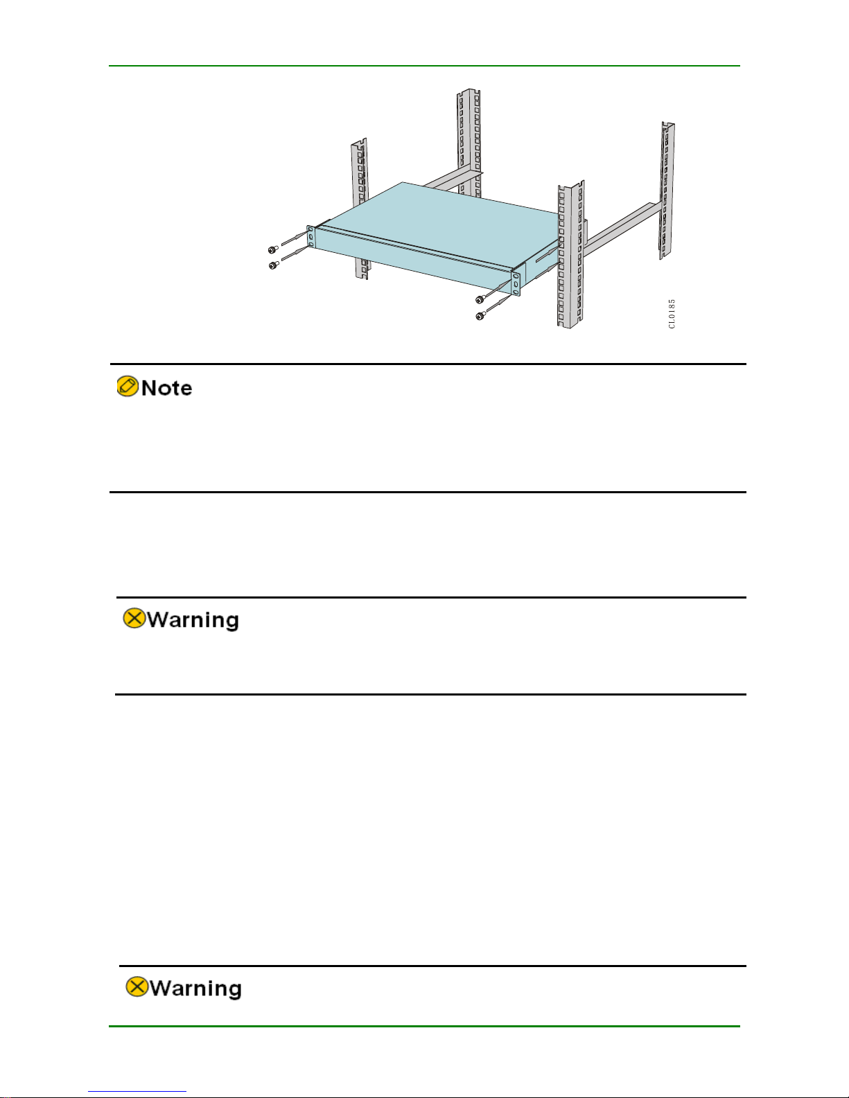
Step 1:
Uplift the router form both sides and place it on the slide (t ray) of the cabinet.
Inset the router to the cabinet s moothly until the hanging ear of the rout er is
closely cling to t he square hole bar in the front of the cabinet. T he slide (tray)
bears the weight. T he router is installed to the 19- inch standard cabinet, as
shown in the following figure.
MyPower S4220 & S4320 Series Switch Installat ion Manual V1.0
Maipu Confidential & Proprietary Information Page 21 of 80
F I G URE 3 - 3 I N S TA L L T HE RO UTE R T O T HE 19- IN C H ST A ND A RD CA B I N E T
If the screw hole on t he hanging ear c annot align to the floating nut installed on the
cabinet correct ly, check the whether the bearing surface of the slide (tray) is on the
integer U boundary and chec k whether the floating nut is installed on the correct hole
position.
Step 2:
Fix the floating nut on the upright square ho le bar of the c hassis hanging ear
and cabinet using the M6 plate screw to prevent the router sliding front and
back.
The hanging ear does not bear the weight. Do not bear t he router only using a hanging
ear without installing the slide (tray).
Check the Installation
After the router is installed t o the cabinet, check the installation based on the follow ing items
and ensure all the items are normal.
Check and ensure t hat the router is installed c orrectly.
Check and ensure t hat t he router hanging ea r and c abinet are secure and well.
Check and ensure t hat enough spac e is reserved a round t he router for heat dissipation.
3.2 Ground the Router
MyPower S4220 & S4320 Series Switch Installat ion Manual V1.0
Maipu Confidential & Proprietary Information Page 22 of 80
For the router and human sec urity, the router must be grounded well. The resistance
between t he router c hassis and the ground shou ld be less than1 ohm.
Generally, t here is t he grounding bar on the c abinet and we c an connect the ground cable of
the router to the grounding bar.
Please use the ground c able carried by the router.
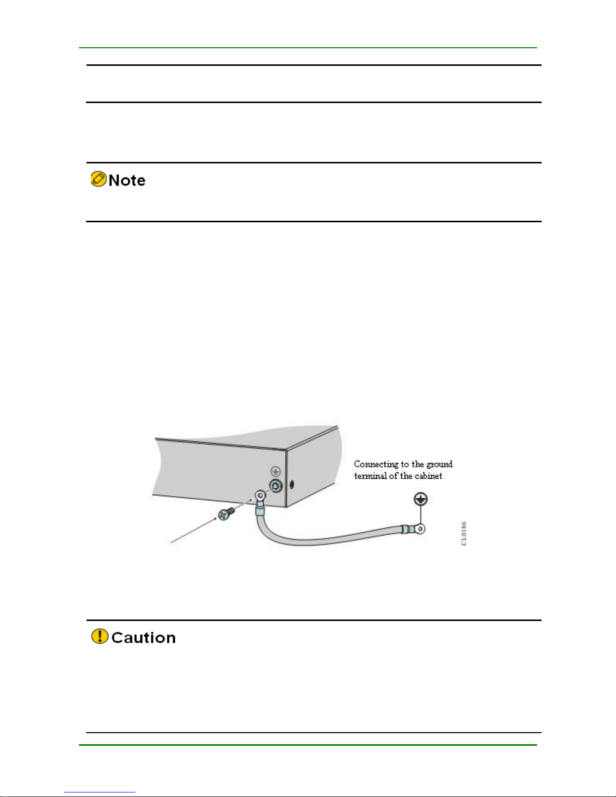
The steps of installing the ground c able are as follows:
Step 1:
Remove t he ground sc rew on the c hassis of the router.
Step 2:
Bind the wiring terminal of the ground c able carried by the router to the ground
screw of the chassis.
Step 3:
Install the ground sc rew with the ground cable to the grounding ho le and
tighten it.
Step 4:
Use the sa me method to install the other side of the ground c able to the
grounding terminal of the c abinet.
F I G URE 3 - 4 C O NN EC T T HE GR O U N D CA BL E
If there is no appropriate grounding point on t he cabinet, we also can connect t he
grounding c able of the router to other grounding bar of the installation place.
Fire hose and lightning rod g rounding of the building a re not the proper grounding
locat ion; t he grounding cable of the router should be connected to the engineering
grounding of the equipment room.
MyPower S4220 & S4320 Series Switch Installat ion Manual V1.0
Maipu Confidential & Proprietary Information Page 23 of 80
3.3 (Optional) Install Interface Daughter
Card Components
If the installed router c ontains the RM2B-3G interfac e daughter c ard, t he USIM card and 3G
antenna need to be installed.
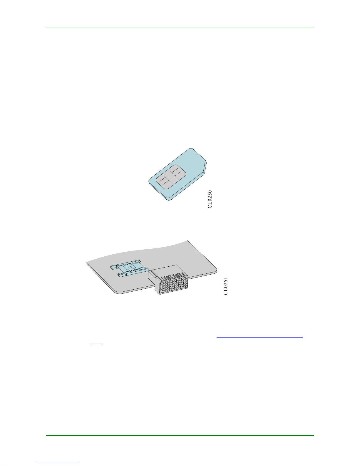
3.3.1 Install USIM Card
The USIM card is shown in the following figure.
F I G URE 3 - 5 U S I M C A RD
The specific position of the RM2B-3G interface daughter c ard USIM card slots on the board is
as shown in the following figure.
F I G URE 3 - 6 U S I M C A RD SL O T P OS I TI O N
When inst alling the USIM card, perform the following steps:
Step 1:
Remove t he RM2B-3G interface daughter card from the router. For how to
remove the interfac e daughter c ard, refer to 6.1 Change Interface Daught er
Card.
Step 2:
Check the USIM s lot position on the board according to the preceding figure.
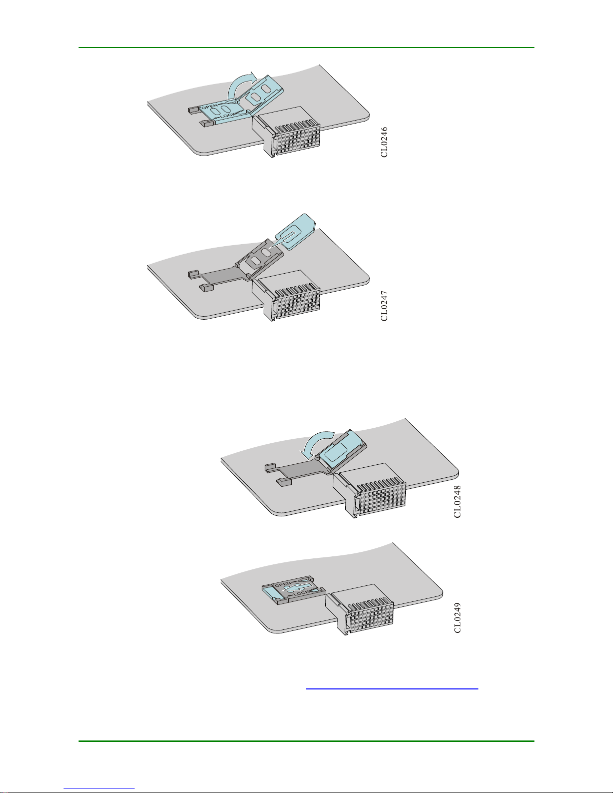
Step 3:
Push the buckle ho rizontally in the OPEN arrow direction to shift the buckle for
about 2 mm. at this time, the buc kle will become loose and slightly upsprung.
Then turn over t he buckle manually.
MyPower S4220 & S4320 Series Switch Installat ion Manual V1.0
Maipu Confidential & Proprietary Information Page 24 of 80
F I G URE 3 - 7 T U R N O V E R T HE B U CKL E
Step 4:
Insert the USIM card into the buc kle.
F I G URE 3 - 8 I N S ERT T H E U S I M CA RD I NTO T H E B U C KL E
Step 5:
Turn upside dow n the buc kle inserted with the USIM c ard and lay it flat. After
the buckle is laid flat, push the buckle horizontally according to t he LOCK arrow
direction to shift the buckle for about 2 mm.
F I G URE 3 - 9 P R ES S T HE B U C K L E DO W N
F I G URE 3 - 10 P US H T HE B U CKL E I N T HE L OC K A RR O W DI R E CT I O N
Step 6:
Install the RM2B-3G interfac e daughter c ard to t he router. For how to install the
interface daughter c ard, refer to 6.1 Change Interface Daughter Card.
 Loading...