

Maipu MP1800X-40, MP1800X-50, MP1800X-40W, MP1800X-40E Installation Manual

MP1800X Series Router
Installation Manual
V1.0


Copyright Statement
Copyright2017 Maipu Communication Technologies Co., Ltd. All rights reserved.
Without the written approval of the Company, no company or individual is allowed to
extract, reproduce, translate or propagate this Manual, in whole or in part, in whatsoever
manner.
and are the trademarks of Maipu Communication Technologies Co.,
Ltd. All other trademarks, product marks and trade names referenced herein are owned
by their owners respectively.
This Manual may be subject to changes on account of product upgrade or other causes.
Maipu reserves the right to revise this Manual without any notice. Subject to the laws and
regulations, Maipu Communication Technologies Co., Ltd. shall, under no circumstance,
be responsible for any accident, negligence, breach of contract, defamation and
infringement of copyright or intellectual property right incurred by using the related
content of this Product Manual or this website, assume any liabilities for damage with
respect to any special, incidental, indirect or secondary losses and any losses on profit,
data, business reputation or expected economy so caused or bear any legal liabilities so
arisen.
Safety Statement
Important! Please read the product safety and compatibility information before energizing
and enabling the product.
Environmental Statement
This product complies with the design requirements in terms of environmental protection
and shall be stored, used and disposed in accordance with the related national laws and
regulations.

Preface
MP1800X Series Router Installation Manual
ii
copyright2017Maipu, all rights reserved
Preface
Manual Introduction
This manual introduces the appearance, hardware, and installation preparation and
method of the MP1800X series router, as well as its basic use and daily maintenance
in terms of energization & operation, troubleshooting and equipment maintenance.
Product Version
This manual is applicable to the product versions as below.
Product name
Product Version
MP1800X series router
MP1800X-40
MP1800X-40W
MP1800X-40E
MP1800X-50
Target Users
The major target users of this Manual are:
Hardware Installation Engineer
Debugging Engineer
Site Maintenance Engineer
System Maintenance Engineer
Convention
Convention of screen output formats
Format
Description
Screen print
Screen output
MP1800X Series Router
Preface
copyright2017Maipu, all rights reserved
iii
Format
Description
Keywords of Screen print
Key information of screen output (red part)
Convention of icons and signs
Format
Description
Note:
Supplement to or emphasis on the aforesaid.
Caution:
Matters that need attention while installing or operating the
equipment, which are important for proper installation and
operation.
Warning:
Operations prohibited or required to follow the specified steps;
otherwise, personal injuries or equipment damages are possible.
Convention of command formats
Format
Description
Bold
Keywords of command line
Italic
Parameters of command line
Brace “{ }”
Options in the brace are compulsory.
Bracket “[ ]”
Options in the bracket are optional.
Angle bracket “<>”
Information in the angle bracket is not displayed.
Square bracket “【】”
Contents in the square bracket need attention.
Upright slash “|”
A sign to separate the options, with the same meaning as “or”.
Slash “/”
A sign to separate the options, indicating a multi-choice
operation.
For the purpose of this manual, the icons have the definitions as below:
Icons
Description
Preface
MP1800X Series Router Installation Manual
iv
copyright2017Maipu, all rights reserved
Icons
Description
This icon and its related description generally refer to the
switch.
Product Details
The manual matching with the product is as follows:
Manual
Description
MP1800X Series Router
Configuration Manual
Detailed introduction to the methods and steps of
configuring the equipment software functions, with the
typical cases made available for reference.
Technical Support
Technical support hotline: 400-65710935 & 400-886-8669
Email (feedback): support@maipu.com
Revision History
The Revision History is the summary of all manual updates. The latest version includes
all previous updates.
Version
Revision
date
Description
V1.0
2017-6-15
First issue

MP1800X Series Router
Preface
copyright2017Maipu, all rights reserved
v
Content
PREFACE ················································································································· II
1 PRODUCT INTRODUCTION ················································································· 1-1
1.1 PRODUCT APPEARANCE AND HARDWARE STRUCTURE ··················································· 1-1
1.1.1 MP1800X-40 ··································································································· 1-1
1.1.2 MP1800X-40W ································································································ 1-2
1.1.3 MP1800X-40E ································································································· 1-3
1.1.4 MP1800X-50 ··································································································· 1-3
1.2 POWER INTRODUCTION ························································································ 1-4
2 INSTALLATION PREPARATION ··········································································· 2-5
2.1 OPERATING ENVIRONMENT INSPECTION ··································································· 2-5
2.1.1 MACHINE ROOM INSPECTION ················································································· 2-5
2.1.2 POWER SYSTEM INSPECTION ················································································· 2-5
2.2 SAFETY PRECAUTIONS ························································································· 2-6
2.2.1 GENERAL SAFETY ······························································································ 2-6
2.2.2 ELECTRICAL SAFETY ·························································································· 2-6
2.2.3 STATIC SAFETY ································································································· 2-6
2.3 INSTALLATION TOOLS, INSTRUMENTS, AND EQUIPMENT ················································ 2-7
2.4 UNPACKING INSPECTION ······················································································· 2-8
3 ROUTER INSTALLATION ···················································································· 3-1
3.1 EXAMPLE 1 OF INSTALLING ROUTER ········································································ 3-1
3.1.1 INSTALLING THE ROUTER HORIZONTALLY ·································································· 3-1
3.1.2 INSTALL THE ROUTER VERTICALLY ·········································································· 3-2
3.2 EXAMPLE 2 OF INSTALLING THE ROUTER ··································································· 3-2
3.2.1 INSTALL ROUTER TO WORKBENCH ··········································································· 3-3
3.2.2 INSTALLING THE ROUTER TO THE CABINET ································································· 3-3
4 ENERGIZATION AND OPERATION ······································································· 4-1
4.1 EQUIPMENT LOGIN ····························································································· 4-1
4.1.1 CONNECTING THE CONFIGURATION CABLE ································································ 4-1
4.1.2 SETTING THE HYPERTERMINAL PARAMETERS OF PC ······················································ 4-2

Preface
MP1800X Series Router Installation Manual
vi
copyright2017Maipu, all rights reserved
4.1.3 ENERGIZATION ································································································· 4-5
4.1.4 POST-ENERGIZATION INSPECTION ············································································ 4-6
4.2 NETWORK ACCESS ····························································································· 4-12
4.2.1 NETWORK ACCESS VIA ETHERNET TWISTED PAIR ························································ 4-12
4.3 HARDWARE MANAGEMENT ··················································································· 4-12
4.3.1 VIEWING THE SOFTWARE AND HARDWARE VERSIONS OF THE ROUTER ······························· 4-13
4.3.2 VIEWING THE SYSTEM ENVIRONMENT TEMPERATURE ··················································· 4-14
4.3.3 VIEWING THE 4G MODULE INFORMATION ································································· 4-14
5 TROUBLESHOOTING ························································································ 5-15
5.1 CONFIGURATION SYSTEM TROUBLESHOOTING ··························································· 5-15
5.1.1 NO-DISPLAY FAILURE TROUBLESHOOTING ································································ 5-15
5.1.2 MESSY CODE TROUBLESHOOTING ·········································································· 5-15
5.2 POWER FAILURE TROUBLESHOOTING······································································ 5-16
5.3 GAIN TECHNICAL SUPPORTING ·············································································· 5-16
6 ROUTER MAINTENANCE ···················································································· A-1
6.1 DE-DUST THE ROUTER ·························································································· A-1
6.1.1 DE-DUST THE BOARD ·························································································· A-1
APPENDIX ············································································································· A-2
A Specifications of the Router and Common Modules ·························································· A-2
A1 Dimension/Weight/Power Consumption······································································· A-2
A2 Power Adapter Specifications ··················································································· A-3
A2.1 AD24-1S0N Power Adapter ·················································································· A-3
B Specifications of Common Interfaces ··········································································· B-4
B1 Console Port Properties ·························································································· B-4
B2 Properties of 10Base-T/100Base-TX/1000Base-T RJ45 Electrical Interface ··························· B-4
B3 Properties of USB Interface ····················································································· B-5
C Cable ················································································································· C-1
C1 Console Cable ····································································································· C-1
C2 Ethernet Electrical Interface Cable ············································································· C-2
C3 WIFI Antenna ····································································································· C-3

MP1800X Series Router
Preface
copyright2017Maipu, all rights reserved
vii
C4 4G Antenna ········································································································ C-3
D Requirements for Equipment Operating Environment ························································ D-3
D1 Requirements for equipment room environment ····························································· D-3
D1.1 Architectural requirements for equipment room ··························································· D-3
D1.2 Requirements for environmental adaptability······························································· D-3
D1.3 Cleanliness requirements ······················································································ D-5
D1.4 Anti-interference requirements ··············································································· D-6
D1.5 Grounding requirements ······················································································· D-6
D2 Requirements for power supply condition ····································································· D-6
D2.1 Requirements for fundamental AC power supply ·························································· D-6
D2.2 DC Power Requirement ······················································································· D-7
D2.3 Suggestions on fundamental AC power supply ····························································· D-8
E Equipment Grounding Specifications and Protection ·························································· E-1
E1 Equipment grounding specifications ··········································································· E-1
E1.1 General grounding specifications ············································································· E-1
E1.2 Grounding specifications for the building of equipment rooms ·········································· E-1
E1.3 Equipment grounding specifications ········································································· E-1
E1.4 Grounding specifications for communication power ······················································· E-2
E1.5 Specifications for ground cable laying ······································································· E-3
E2 Equipment protection ···························································································· E-4
E2.1 General requirements for lightning protection cable layout ··············································· E-4
E2.2 Cabling and installation methods ············································································· E-5
E2.3 Equipotential bonding requirements and method ··························································· E-5
F Environmental Substance Statement ············································································· F-6

Preface
MP1800X Series Router Installation Manual
viii
copyright2017Maipu, all rights reserved
Figures
FIGURE 1-1 MP1800X-40 APPEARANCE ....................................................................................................................... 1-1
FIGURE 1-2 MP1800X-40W APPEARANCE .................................................................................................................... 1-2
FIGURE 1-3 MP1800X-40E APPEARANCE ..................................................................................................................... 1-3
FIGURE 1-4 MP1800X-50 APPEARANCE ....................................................................................................................... 1-4
FIGURE 1-6 POWER ADAPTER APPEARANCE .................................................................................................................. 1-4
FIGURE 2-1 USAGE OF THE ESD WRIST ......................................................................................................................... 2-7
FIGURE 3-1 THE DIAGRAM OF THE TABLE TOP PLACEMENT ................................................................ ............................ 3-1
FIGURE 3-2 THE DIAGRAM OF THE DESKTOP FIXING ....................................................................................................... 3-2
FIGURE 3-3 THE DIAGRAM OF THE VERTICAL INSTALLATION ........................................................................................... 3-2
FIGURE 3-4 THE MINIMUM HEIGHT OF THE TRAY ............................................................................................................. 3-4
FIGURE 3-5 INSTALL THE FLOATING NUTS ....................................................................................................................... 3-5
FIGURE 3-6 INSTALL THE ROUTER TO THE 19-INCH STANDARD CABINET ....................................................................... 3-6
FIGURE 4-1 CONNECTING THE ROUTER AND THE PC THROUGH THE RS-232 SERIAL PORT ......................................... 4-1
FIGURE 4-2 “LOCATION INFORMATION” INTERFACE ........................................................................................................ 4-2
FIGURE 4-3 THE TELEPHONE AND MODEM INTERFACE ................................................................................................. 4-3
FIGURE 4-4 “CONNECTION DESCRIPTION” INTERFACE ................................................................................................... 4-3
FIGURE 4-5 “CONNECT TO” INTERFACE .......................................................................................................................... 4-3
FIGURE 4-6 THE COM1 PROPERTIES INTERFACE ......................................................................................................... 4-4
FIGURE 4-7 THE TEST-HYPERTERMINAL INTERFACE ..................................................................................................... 4-4
FIGURE 4-8 “TEST PROPERTIES” INTERFACE .................................................................................................................. 4-5
FIGURE 4-9 THE TEST-HYPERTERMINAL INTERFACE AFTER SETTING ............................................................................ 4-5

MP1800X Series Router
Preface
copyright2017Maipu, all rights reserved
ix
Appendix Figures
APPENDIX FIGURE A-1 AD24-1S0N POWER ADAPTER ................................................................................................ A-3
APPENDIX FIGURE C-1 THE DIAGRAM OF THE CONSOLE CABLE ................................................................................... C-1
APPENDIX FIGURE C-2 RJ45 BASE ............................................................................................................................... C-2
APPENDIX FIGURE C-3 WIFI ANTENNA ......................................................................................................................... C-3
APPENDIX FIGURE C-4 4G ANTENNA ............................................................................................................................. C-3
APPENDIX FIGURE E-1 THE DIAGRAM OF DEVICE EQUIPOTENTIAL BONDING ................................................................ E-5

Preface
MP1800X Series Router Installation Manual
x
copyright2017Maipu, all rights reserved
Tables
TABLE 4-1 MP1800X-40E INDICATOR DESCRIPTION .................................................................................................. 4-6
TABLE 4-2 MP1800X-40W INDICATOR DESCRIPTION ................................................................................................... 4-8
TABLE 4-3 MP1800X-40/SJW12-4G INDICATOR DESCRIPTION .................................................................................. 4-9
TABLE 4-4 MP1800X-50 INDICATOR DESCRIPTION ..................................................................................................... 4-11
TABLE 4-5 THE DESCRIPTION FOR THE KEY FIELDS OF THE INFORMATION DISPLAYED BY THE SHOW VERSION
COMMAND .............................................................................................................................................................. 4-13

MP1800X Series Router
Preface
copyright2017Maipu, all rights reserved
xi
Appendix Tables
APPENDIX TABLE A-1DIMENSION ................................................................................................................................... A-2
APPENDIX TABLE B-1 CONSOLE PORT PROPERTIES ..................................................................................................... B-4
APPENDIX TABLE B-2 THE PROPERTIES OF THE 10BASE-T/100BASE-TX/1000BASE-T RJ45 ELECTRICAL
INTERFACE .............................................................................................................................................................. B-4
APPENDIX TABLE B-3 USB INTERFACE PROPERTIES .................................................................................................... B-5
APPENDIX TABLE C-1 CONNECTION RELATIONSHIP OF THE CONSOLE CABLE .............................................................. C-1
APPENDIX TABLE C-2 THE CONNECTION RELATION OF THE RJ45 CABLE (CATEGORY-5 TWISTED PAIR) .................... C-2
APPENDIX TABLE D-1 REQUIREMENTS FOR ENVIRONMENTAL ADAPTABILITY ............................................................... D-3
APPENDIX TABLE D-2 REQUIREMENTS FOR CONTENT OF DUST IN EQUIPMENT ROOM.................................................. D-5
APPENDIX TABLE D-3 CONTENT INDEX OF THE HARMFUL GASES IN EQUIPMENT ROOM .............................................. D-5
APPENDIX TABLE D-4 REQUIREMENT FOR FUNDAMENTAL AC POWER SUPPLY ........................................................... D-7
APPENDIX TABLE D-5 DC POWER REQUIREMENT ......................................................................................................... D-7
APPENDIX TABLE E-1 GENERAL GROUNDING SPECIFICATIONS .................................................................................... E-1
APPENDIX TABLE E-2 EQUIPMENT GROUNDING SPECIFICATIONS ................................................................................. E-1
APPENDIX TABLE E-3 GROUNDING SPECIFICATIONS FOR COMMUNICATION POWER.................................................... E-2
APPENDIX TABLE E-4 SPECIFICATIONS FOR GROUND CABLE LAYING ........................................................................... E-3
APPENDIX TABLE F-1 TOXIC AND HARMFUL SUBSTANCE NAME AND CONTENT IDENTIFICATION ...................................F-6


MP1800X Series Router
Product Introduction
copyright2017Maipu, all rights reserved
1-1
1 Product Introduction
1.1 Product Appearance and Hardware Structure
MP1800X series router includes MP1800X-40, MP1800X-40W, MP1800X-40E,
MP1800X-50, SJW12-4G.
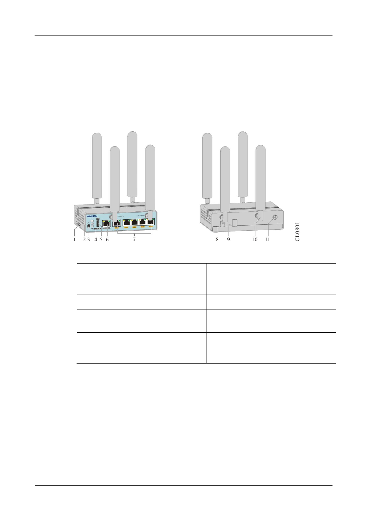
1.1.1 MP1800X-40
MP1800X-40 router supports one console port, one USB interface, five
10M/100M/1000M Ethernet ports, as well as TD-LTE, FDD-LTE, TD-SCDMA, WCDMA,
EVDO, CDMA 1x, GSM network. The dual SIM card slots can be switched via the DIP
switch. The device adopts the 12V/24W power adapter to provide power.
MP1800X-40 dimension is 145 x 100 x 38mm (W x D x H).
Figure 1-1 MP1800X-40 appearance
1. SIM card slot
2. Function status indicator
3. Reset button
4. Signal indicator
5. USB interface
6. RJ45 CONSOLE port
7. 10/100/1000Base-T Ethernet electrical
interface
8. Power interface
Product Introduction
MP1800X Series Router Installation Manual
1-2
copyright2017Maipu, all rights reserved
9. System power status indicator
10. SIM card DIP switch
11. SMI card switching description
12. 4G antenna
13. Grounding screw
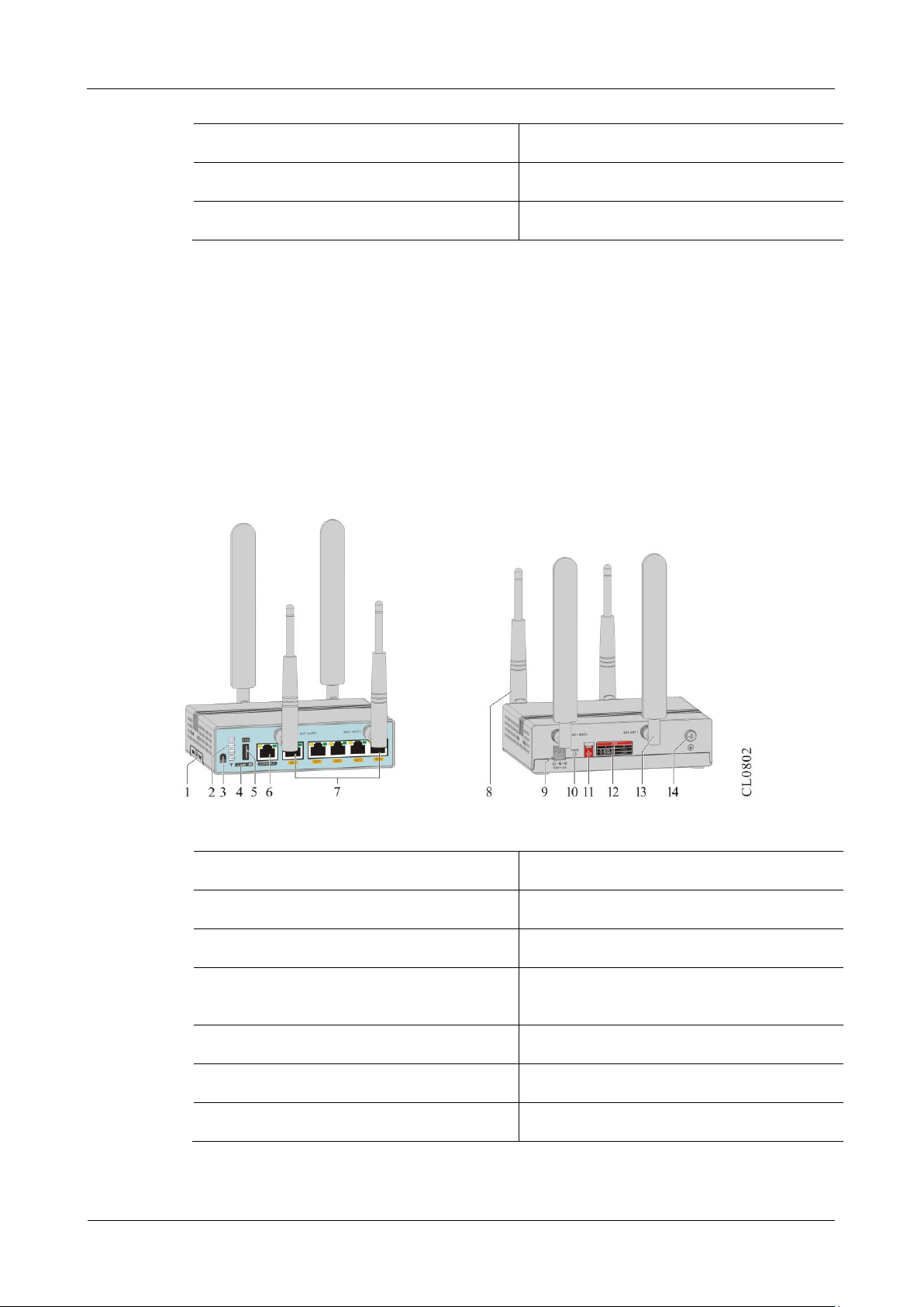
1.1.2 MP1800X-40W
MP1800X-40W router supports one console port, one USB interface, five
10M/100M/1000M Ethernet ports, supports TD-LTE, FDD-LTE, TD-SCDMA, WCDMA,
EVDO, CDMA 1x, and GSM network, and supports WIFI(IEEE 802.11b/g/n). The dual
SIM card slots can be switched via the DIP switch. The device adopts the 12V/24W
power adapter to provide power.
MP1800X-40W dimension is 145 x 100 x 38mm (W x D x H).
Figure 1-2 MP1800X-40W appearance
1. SIM card slot
2. Function status indicator
3. Reset button
4. Signal indicator
5. USB interface
6. RJ45 CONSOLE port
7. 10/100/1000Base-T Ethernet electrical
interface
8. WIFI antenna
9. Power interface
10. System power status indicator
11. SIM card DIP switch
12. SMI card switching description
13. 4G antenna
14. Grounding screw
MP1800X Series Router
Product Introduction
copyright2017Maipu, all rights reserved
1-3
1.1.3 MP1800X-40E
MP1800X-40E router supports one console port, one USB interface, five
10M/100M/1000M Ethernet ports, supports TD-LTE, FDD-LTE, TD-SCDMA, WCDMA,
EVDO, CDMA 1x, and GSM network, and supports dual 4G and dual-card
dual-standby . The device adopts the 12V/24W power adapter to provide power.
MP1800X-40E dimension is 145 x 100 x 38mm (W x D x H).
Figure 1-3 MP1800X-40E appearance
1. SIM card slot
2. Function status indicator
3. Reset button
4. Signal indicator
5. USB interface
6. RJ45 CONSOLE port
7. 10/100/1000Base-T Ethernet electrical
interface
8. Power interface
9. System power status indicator
10. 4G antenna
11. Grounding screw
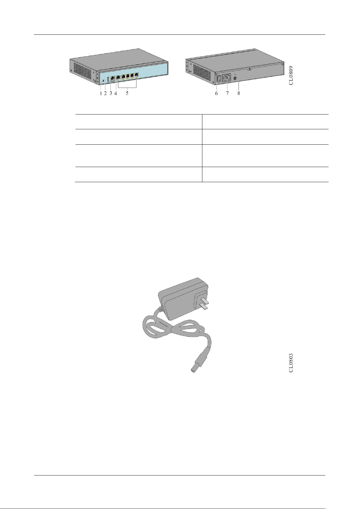
1.1.4 MP1800X-50
MP1800X-50 router supports one console port, one USB interface, five
10M/100M/1000M Ethernet ports.
MP1800X-50 dimension is 260 x 190 x 44.2mm (W x D x H).
Product Introduction
MP1800X Series Router Installation Manual
1-4
copyright2017Maipu, all rights reserved
Figure 1-4 MP1800X-50 appearance
1. Reset button
2. Function status indicator
3. USB interface
4. RJ45 CONSOLE port
5. 10/100/1000Base-T Ethernet electrical
interface
6. Power switch
7. Power socket
8. Grounding screw
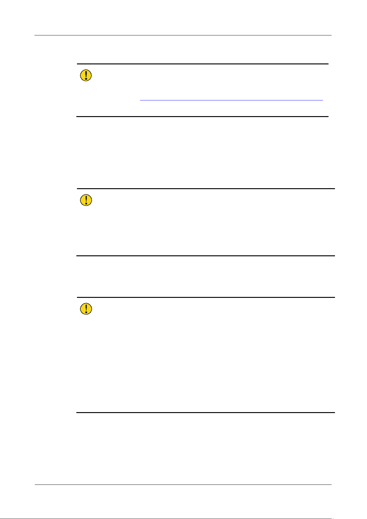
1.2 Power Introduction
MP1800X-40, MP1800X-40W, MP1800X-40E, SJW12-4G adopt the external power
adapter AD24-1S0N to provide the power. The output voltage of the power adapter is
12V and the output power is 24W. MP1800X-50 adopts the inbuilt fixed power, and is
connected with the external electric power supply.
The appearance of the AD24-1S0N power adapter is as follows:
Figure 1-5 Power adapter appearance

MP1800X Series Router
Installation Preparation
copyright2017Maipu, all rights reserved
2-5
2 Installation Preparation
Note:
The equipment is accompanied with Packing List. Please verify whether the
accessories are complete and in good conditions accordingly. In case of any
damage or omission, please contact Maipu’s technical support without delay to
request a replacement.
2.1 Operating Environment Inspection
2.1.1 Machine Room Inspection
For the purpose of a smooth operation, the proper measures shall be in place to
maintain the operating conditions of the equipment.
The AC system shall ensure the temperature and humidity suitable for normal
operation. Refer to “Appendix D1 Machine Room Requirements” for details.
A well grounded equipment can work stably, protect against lightning stroke and
interference and satisfy the grounding specifications. Refer to “Appendix E1
Equipment Grounding Specifications” for details.
Check whether the installation space and handling channel are sufficient.
Check whether the machine room satisfies the cleanliness requirements. It is
forbidden to place the equipment in an environment under decoration works and
with high density of dust.
2.1.2 Power System Inspection
A good power system constitutes the basis for energizing and steadily operating the
switch. To meet the power supply requirement of MP1800X series router, use
AD24-1S0N power adapter to provide power for MP1800X-40, MP1800X-40W,
MP1800X-40E, and SJW12-4G. MP1800X-50 can directly adopt the electric power
supply.
Therefore, you are requested to inspect the power system of the installation site only,
which shall work steadily and satisfy the input mode, rated input voltage and other
requirements. Refer to “Appendix D2 Power Conditions and Requirements” for details.
Installation Preparation
MP1800X Series Router Installation Manual
2-6
copyright2017Maipu, all rights reserved
Caution:
Please refer to “Appendix A Specifications of the Router and Common Modules”
for details on the power consumption of the router.
2.2 Safety Precautions
2.2.1 General Safety
Caution:
The floor of the installation site shall be dry and smooth, with the anti-skid measures
in place.
The equipment shall be clean, dust free and placed in a dry environment.
2.2.2 Electrical Safety
Caution:
Please carefully check any potential risks within the working area, including power
ground, grounding reliability and wet ground.
Before installation, it is required to know the location of the emergency power switch
in the equipment room. In case of an accident, the emergency power switch shall be
turned off first.
Two or more personnel are preferred to conduct the live maintenance.
When closing the power, check and ensure that the power is turned off.
2.2.3 Static Safety
The anti-static precautions shall be in place to prevent the electronic elements of the
router from being damaged by the static electricity.
 Loading...