

Page 1

Maipu Confidential & Proprietary Information Page 1 of 95
MP1800-10 3G Router User Manual
V1.2
Maipu Communication Technology Co., Ltd
No. 16, Jiuxing Avenue
Hi-Tech Park
Chengdu, Sichuan Province
P. R. China
610041
Tel: (86) 28-85148850, 85148041
Fax: (86) 28-85148948, 85148139
URL: http:// www.maipu.com
Mail: [email protected]
Page 2

MP1800-10 3G Router User Manual
Maipu Confidential & Proprietary Information Page 2 of 95
All rights reserved. Printed in the People’s Republic of China.
No part of this document may be reproduced, transmitted, transcribed, stored in a retrieval system, or translated into any
language or computer language, in any form or by any means, electronic, mechanical, magnetic, optical, chemical, manual
or otherwise without the prior written consent of Maipu Communication Technology Co., Ltd.
Maipu makes no representations or warranties with respect to this document contents and specifically disclaims any implied
warranties of merchantability or fitness for any specific purpose. Further, Maipu reserves the right to revise this document
and to make changes from time to time in its content without being obligated to notify any person of such revisions or
changes.
Maipu values and appreciates comments you may have concerning our products or this document. Please address comments
to:
Maipu Communication Technology Co., Ltd
No. 16, JiuXing Avenue, Hi-Tech Park
Chengdu, Sichuan Province
P. R. China
610041
Tel: (86) 28-85148850, 85148041
Fax: (86) 28-85148948, 85148139
URL: http:// www.maipu.com
Mail: [email protected]
All other products or services mentioned herein may be registered trademarks, trademarks, or service marks of their
respective manufacturers, companies, or organizations.
Page 3

MP1800-10 3G Router User Manual
Maipu Confidential & Proprietary Information Page 3 of 95
Contents
Product Introduction ................................................................................ 5
Hardware Specifications .......................................................................................... 5
Functions ............................................................................................................... 6
Product Models ....................................................................................................... 7
Product Shapes ...................................................................................................... 7
Online Login .............................................................................................. 9
Environment Requirement ....................................................................................... 9
Using Preparations .................................................................................................. 9
Configure Computer .............................................................................................. 10
Log into System ................................................................................................... 14
Configuration ......................................................................................... 15
System ................................................................................................................ 15
System Time ...................................................................................................................... 16
Remote Logs ...................................................................................................................... 18
Management Control .......................................................................................................... 18
Configuration Management ................................................................................................. 19
System Upgrade ................................................................................................................. 20
SNMP ................................................................................................................................ 21
Modify Password ................................................................................................................. 22
Restart System .................................................................................................................. 22
Log Out ............................................................................................................................. 23
Network ............................................................................................................... 23
Dial Interface ..................................................................................................................... 23
WAN Interface .................................................................................................................... 29
LAN Interface ..................................................................................................................... 35
Forwarding Mode ................................................................................................................ 36
Dynamic Domain Name ...................................................................................................... 36
Static Route ....................................................................................................................... 37
Dynamic Route ................................................................................................................... 38
Manual Online .................................................................................................................... 40
WIFI Setting....................................................................................................................... 41
Service ................................................................................................................ 42
DHCP Setting ..................................................................................................................... 43
Page 4

MP1800-10 3G Router User Manual
Maipu Confidential & Proprietary Information Page 4 of 95
Hot Backup ........................................................................................................................ 45
AAA Configuration .............................................................................................................. 47
802.1x Authentication ......................................................................................................... 48
PIN Code Management ....................................................................................................... 50
Regular Online/Offline ......................................................................................................... 55
Disconnection Detection ...................................................................................................... 55
Multi-WAN Port Service ....................................................................................................... 56
Status Firewall ...................................................................................................... 59
Basic Setting ...................................................................................................................... 59
Access Control .................................................................................................................... 60
Port Mapping ...................................................................................................................... 61
MAC-IP Binding .................................................................................................................. 62
QOS .................................................................................................................... 63
Bandwidth Management ..................................................................................................... 63
VPN Configuration ................................................................................................. 64
IPSec ................................................................................................................................. 64
GRE ................................................................................................................................... 71
Certificate Management ...................................................................................................... 73
Status.................................................................................................................. 78
System Logs ...................................................................................................................... 79
System Information ............................................................................................................ 79
IPSec Tunnel Status ............................................................................................................ 80
Dialer Interface Status ........................................................................................................ 81
WAN Status ....................................................................................................................... 84
LAN Status ......................................................................................................................... 85
Route Information .............................................................................................................. 86
DHCP Information .............................................................................................................. 87
Connection Information ....................................................................................................... 87
GPS Status ........................................................................................................................ 88
CLI ...................................................................................................................... 89
System .............................................................................................................................. 89
Interface ............................................................................................................................ 90
3G ..................................................................................................................................... 90
IPSec ................................................................................................................................. 91
Route ................................................................................................................................ 92
Firewall .............................................................................................................................. 93
DHCP&VRRP ......................................................................................................................... 93
Appendix ................................................................................................ 94
Page 5

MP1800-10 3G Router User Manual
Maipu Confidential & Proprietary Information Page 5 of 95
Product Introduction
This chapter describes the specifications, functions, and product models of
MP1800-10 router, letting you have a primary impression for MP1800-10
router and helping you to use the product better in the future.
1. Hardware specifications
2. Functions
3. Product models
4. Product shapes
Hardware Specifications
1. 3G data
Support two kinds of 3G module, that is, WCDMA and CDMA2000.
2. Interface
Wireless interface: 50Ω/SMA female
SIM/UIM card: 3V
Series data interface (RJ45): RS-232(DCE)
Series data interface rate: 9600 bits/s
Ethernet interface: 10/100BaseT/RJ45 auto-sensing
USB interface (only for RM1800-10C, RM1800-10W, RM1800-10)
802.11b/g/n (only for RM1800-10C, RM1800-10W, RM1800-10)
3. Power supply
Voltage: +12VDC
4. Power consumption
Page 6

MP1800-10 3G Router User Manual
Maipu Confidential & Proprietary Information Page 6 of 95
Idle: 300mA@+12VDC
Max.: 800mA@+12VDC
5. Other parameters
Demission: < 100mm×140mm×35mm (excluding antenna and
installation parts)
Weight: < 1000g
Work environment temperature: -25 - +70℃
Storage temperature: -30 - +70℃
Relative humidity: < 95% (no condensing)
Functions
1. Basic Features
Convenient, flexible, reliable
Support CDMA 2000 and WCDMA
Data terminal online forever
NTP
Remote logs
Remote SSH, Telnet, HTTP management
Local Firmware upgrade/configuration backup
SNMP management
Support DDNS
Inbuilt with DHCP and VRRP services
Firewall and virtual address translation (NAT)
Support packet filter
Support mobile network traffic statistics
Support VPDN and APN private network access
2. Advanced functions
Support IPSEC, GRE
Page 7

MP1800-10 3G Router User Manual
Maipu Confidential & Proprietary Information Page 7 of 95
Support Windows 2008/2003, CMS offline digital certificate
Support Windows 2008/2003, CMS online digital certificate
Support dialing on demand and online forever
Support static route, black hole route, dynamic route RIP v2
Support PIN code management of SIM card
Support AAA login authentication
Support 802.1x authentication
Support disconnection detection
Support multi-WAN port backup
Support getting time via 3G
Support regular online/offline
Support E3G management
Product Models
MP1800-10 router adopts the general basic platform and individual
application to adapt the different industry application requirements and
network environment of the carrier. Currently, MP1800-10 series router
has various models. To distinguish the product models, we describe as
follows:
MP1800-10 router models: RM1800-10x
Table 2-1: Product model list
x
Network type
W
WCDMA
C
CDMA2000
No letter
Outer USB 3G
Product Shapes
1. Front Panel
Page 8
MP1800-10 3G Router User Manual
Maipu Confidential & Proprietary Information Page 8 of 95
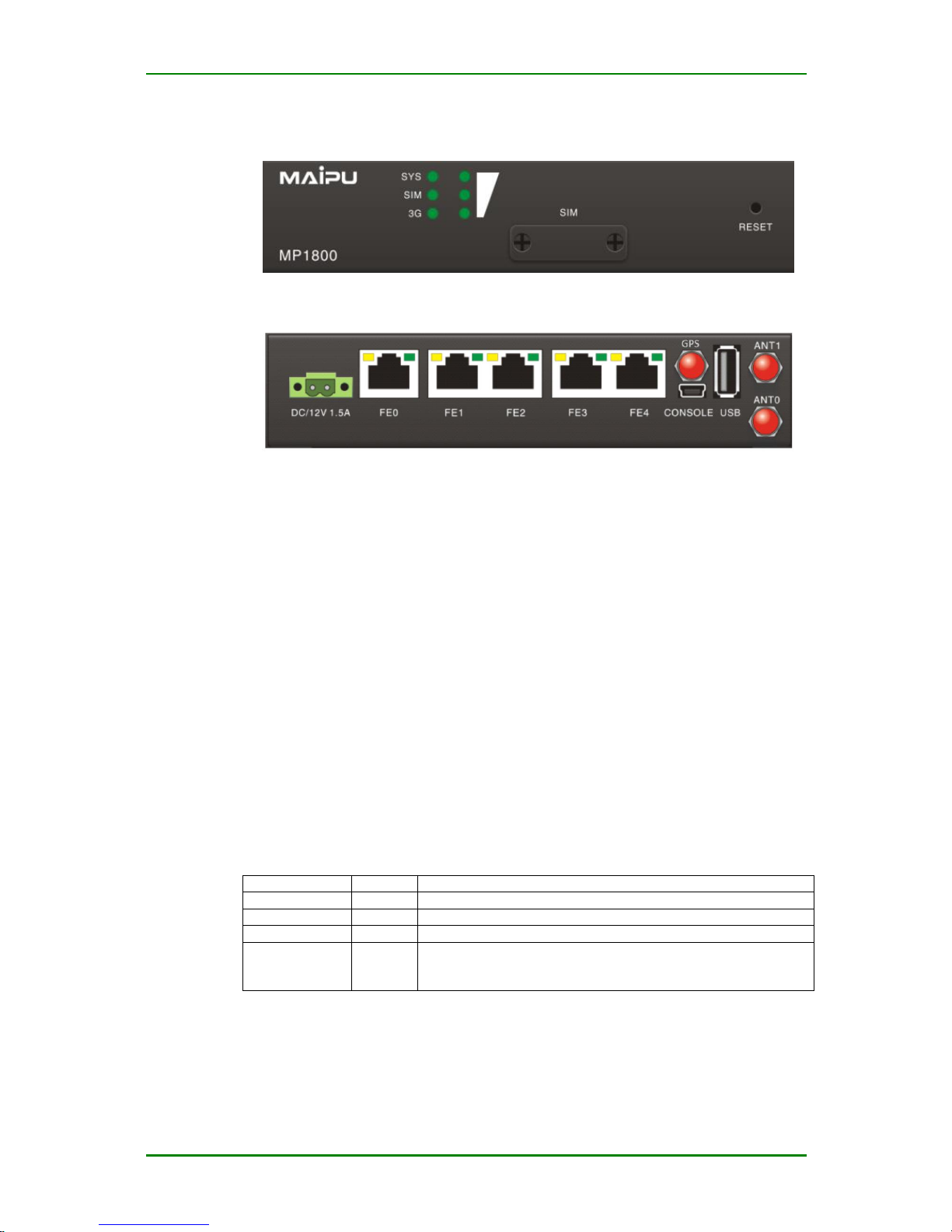
RM1800-10x:
Front panel
Back panel
RESET: The reset button; press the button for 2-3s with power and the
system resets; press the button for 6-10s and the device restores the
factory setting.
CONSOLE: Serial console platform; the baud rate is 9600, 8-bit data bit,
no parity, one-bit stop bit.
FE0-FE4: RJ45 Ethernet interface.
USB: Outer USB interface.
ANT0 is 3G antenna, ANT1 is WIFI antenna
The outer power adaptor is DC 12V/1.5A.
Indicator description:
Indicator
Status
Description
SYS
Flash
The system already runs normally
SIM
On
The SIM card is connected normally
3G
Flash
3G has data received and sent
3G signal
indicator
On
Indicate the signal intensity. When the signals are strongest,
three indicators are all on; when there is no signal, three
indicators are all off.
Page 9

MP1800-10 3G Router User Manual
Maipu Confidential & Proprietary Information Page 9 of 95
Online Login
This chapter describes the using requirement, installation wiring, and
configuration login of MP1800-10 router, which can help you log into the
management system of the product.
1. Environment requirement
2. Using preparations
3. Configure computer
4. Log into system
Environment Requirement
The requirements of MP1800-10 router for the using environment:
Work environment temperature: -25 - +70℃
Storage temperature: -30 - +70℃
Relative humidity: < 95% (no condensing)
Using Preparations
To configure using MP1800-10 router, you need to prepare as follows:
One computer:
1. Computer with Ethernet adapter and TCP/IP protocol
2. IE 8.0 browser (other browser also can ensure the normal using of
the functions)
3. It is recommended to adopt 1024x768 resolution to display
One UIM(/SIM) card
Page 10
MP1800-10 3G Router User Manual
Maipu Confidential & Proprietary Information Page 10 of 95
Caution
The starting order of the device is: Insert SIM card > Insert antenna >
Power on. If the starting order is wrong, maybe the functions of the device
cannot be used normally.
Configure Computer
The following takes the LAN connection mode and adopts Windows XP as
an example to describe the configuration steps of the computer network
connection.
1. Method 1:
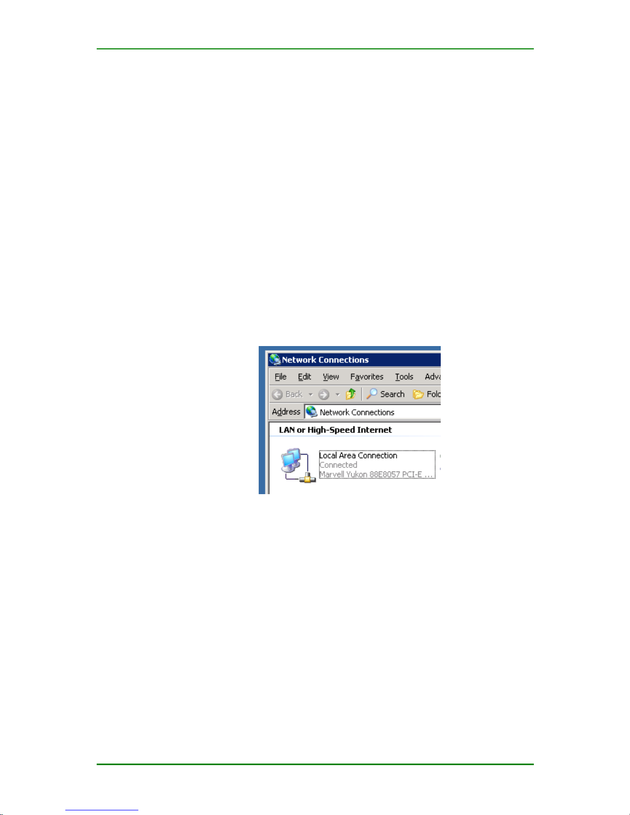
In LAN, select one computer for configuration and enter Control Panel >
Network Connection, as shown in the following figure. Select Local
Connection of the network adapter on the interface.
Configure local connection of the computer
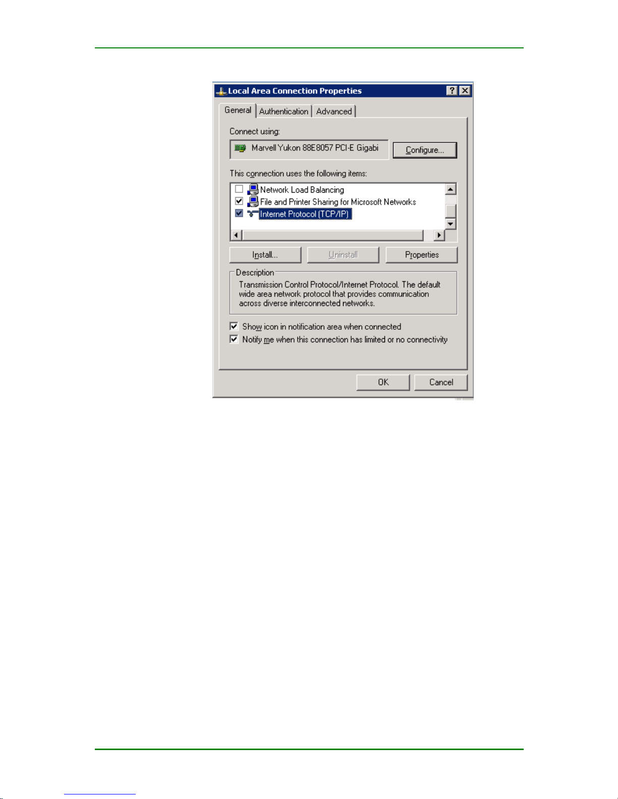
Enter (double-click or right-click) Local Connection > Properties, as
shown in the following figure:
Page 11
MP1800-10 3G Router User Manual
Maipu Confidential & Proprietary Information Page 11 of 95
Configure local connection properties of the computer
Select Internet Protocol (TCP/IP) and click Properties to enter the
following figure:
Page 12
MP1800-10 3G Router User Manual
Maipu Confidential & Proprietary Information Page 12 of 95
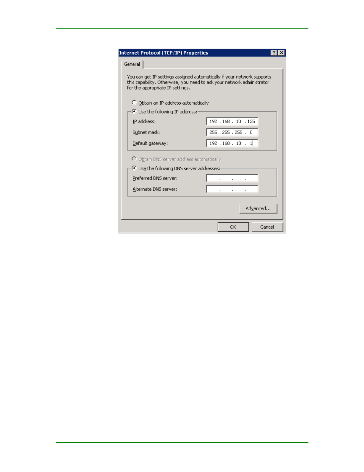
TCP/IP attribute configuration
The configuration is as follows:
IP address: 192.168.10.* (* refers to any integer from 2-254).
Subnet mask: 255.255.255.0
Default gateway: 192.168.10.1
After configuration, click OK.
Caution
1. The method interrupts the communication between the computer and
LAN for a moment.
2. The factory setting of MP1800-10 router LAN interface:
IP address: 192.168.10.1
Subnet mask: 255.255.255.0
2. Method 2
Page 13
MP1800-10 3G Router User Manual
Maipu Confidential & Proprietary Information Page 13 of 95
In the previous network configuration environment, when you do not want
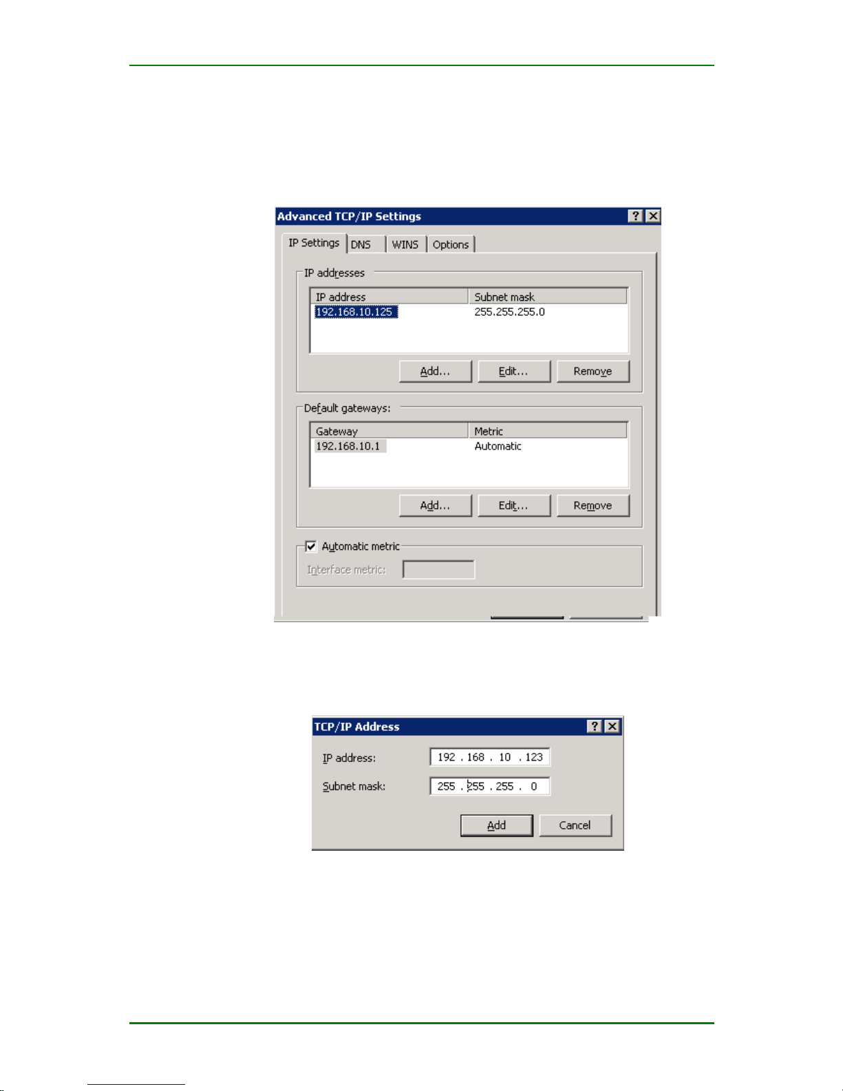
to interrupt the communication between the local PC and LAN, but still can
configure MP1800-10 router, you can consider adding route (IP) to realize.
Click Advanced in the above figure 3-3, as shown in Figure 3-3:
Advanced configuration interface of TCP/IP attributes
Click Add (A) in “IP address (R)” of Figure 3-4, input the desired IP
address, as shown in the following figure:
Interface for adding TCP/IP address
After configuration, click Add. In this way, one route to MP1800-10 router
is added.
Note
Page 14
MP1800-10 3G Router User Manual
Maipu Confidential & Proprietary Information Page 14 of 95
If you just configure MP1800-10 router, we recommend you to select
Method 2, which can save time.
Log into System
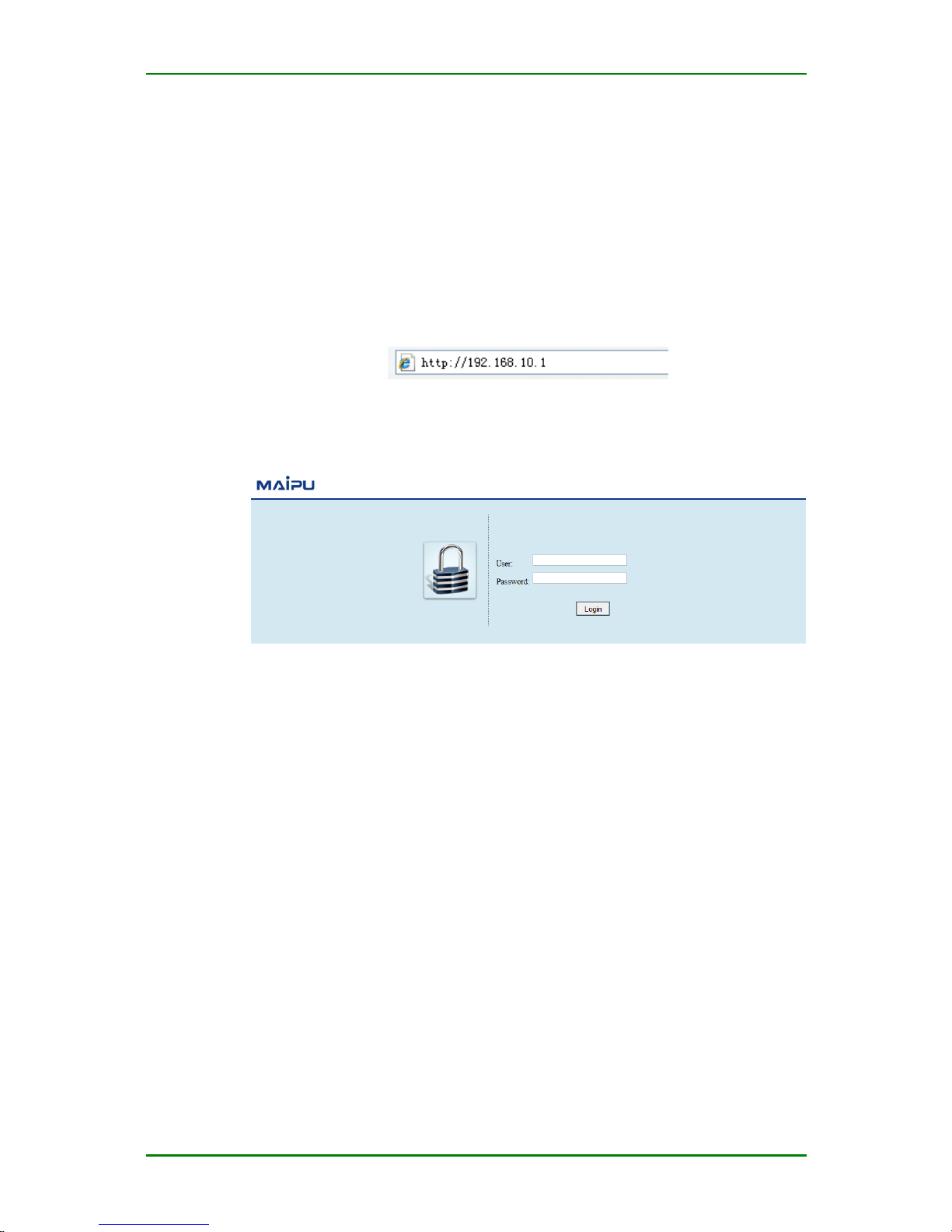
Open and configure the IE browser of the computer and input
http://192.168.10.1/ in the address bar.
Web login
Press Enter to enter the login interface of the user, as follows:
User login authentication
When the user logs into the system for the first time, it is necessary to
adopt the default user name and password:
User name: admin
Password: admin
After inputting correctly, the user can log into the web configuration
interface of MP1800-10 router.
Page 15

MP1800-10 3G Router User Manual
Maipu Confidential & Proprietary Information Page 15 of 95
Configuration
This chapter describes how to configure MP1800-10 router via web, the
functions, configuration parameters, precautions, and problems of the
product.
1. System
2. Network
3. Service
4. Status firewall
5. QoS
6. VPN configuration
7. Status
8. CLI
System
The system tool of MP1800-10 router provides the following functions
for you to manage the system:
System time
Remote logs
Management control
Configuration management
System upgrade
SNMP
Modify password
System restarting
Page 16
MP1800-10 3G Router User Manual
Maipu Confidential & Proprietary Information Page 16 of 95
Log out
System Time
MP1800-10 provides three kinds of clock synchronizing modes, that is,
manual setting, NTP network time and get time via 3G module.
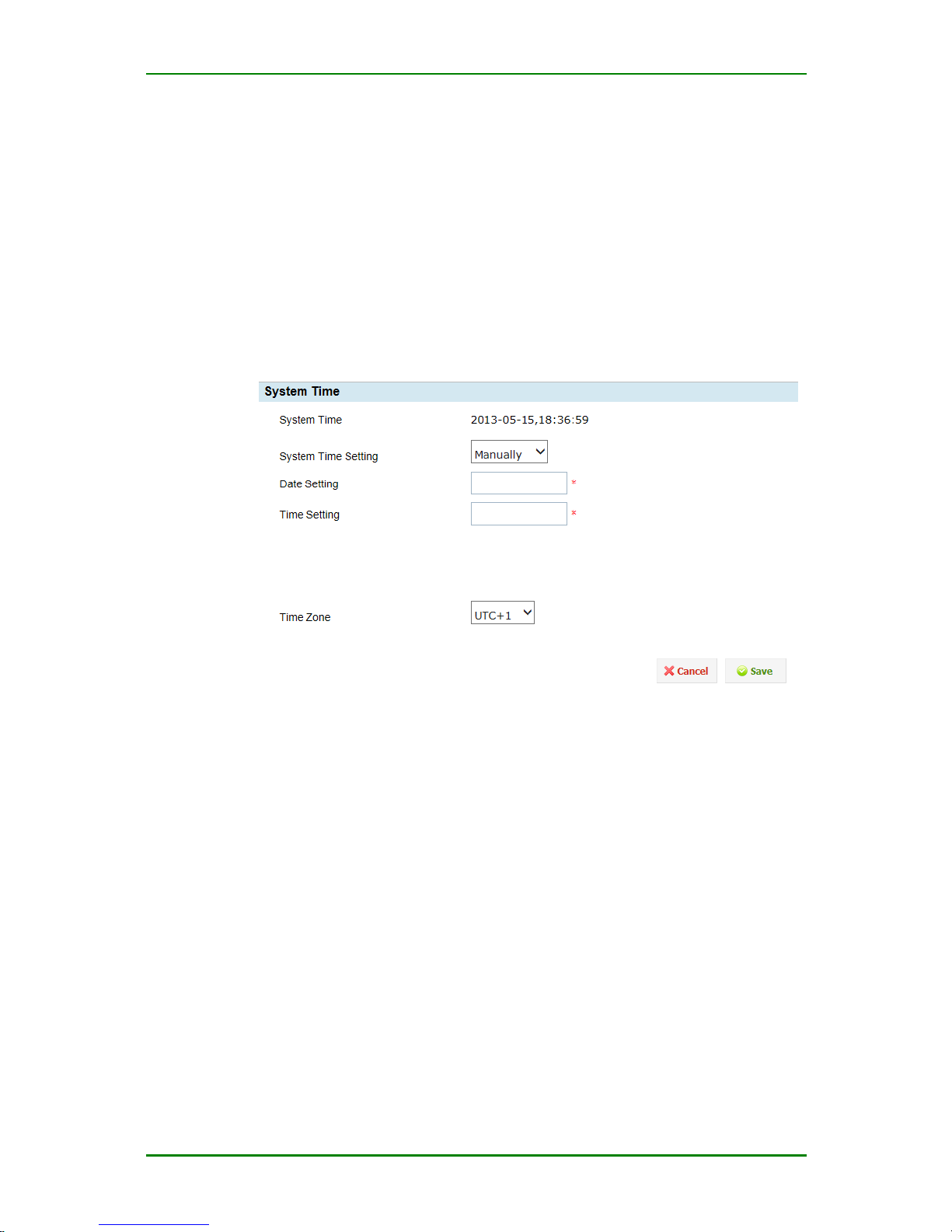
1. Manual setting
Enter System > System Time and you can see the interface for setting
time manually, as follows:
Interface for setting time manually
Current time: Display current system time
System time setting: Manual setting/time server
Date setting: Set system date
Time setting: Set system time
Time Zone: Specify the time zone of the country against UTC
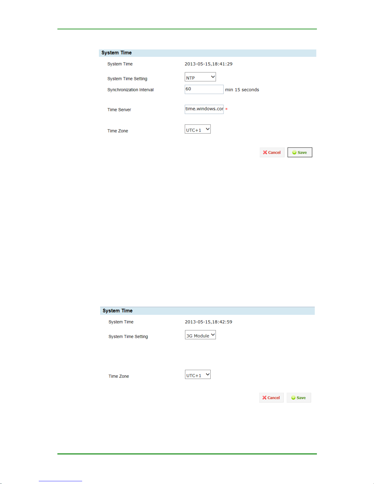
2. NTP Synchronizing Time Setting
NTP (network time protocol), that is, synchronize time automatically via
the local host and network clock server. Enter System > System Time
and you can see the following interface for configuring time server:
Page 17
MP1800-10 3G Router User Manual
Maipu Confidential & Proprietary Information Page 17 of 95
NTP configuration interface
Synchronization interval: Set the interval of synchronizing time.
Time server: Specify the domain name or IP address of the server
providing the service of synchronizing time.
Time Zone: Specify the time zone of the country against UTC
Caution
NTP server is not sure to be the server on Internet, but should be the
server that MP1800-10 router can access.
3. Setting via 3G module
Get time via 3G module
Page 18
MP1800-10 3G Router User Manual
Maipu Confidential & Proprietary Information Page 18 of 95
Caution
When setting the time via the 3G module, the device should be inserted
with the available SIM card and it can take effect only after restarting the
device.
Time Zone: Specify the time zone of the country against UTC
Remote Logs
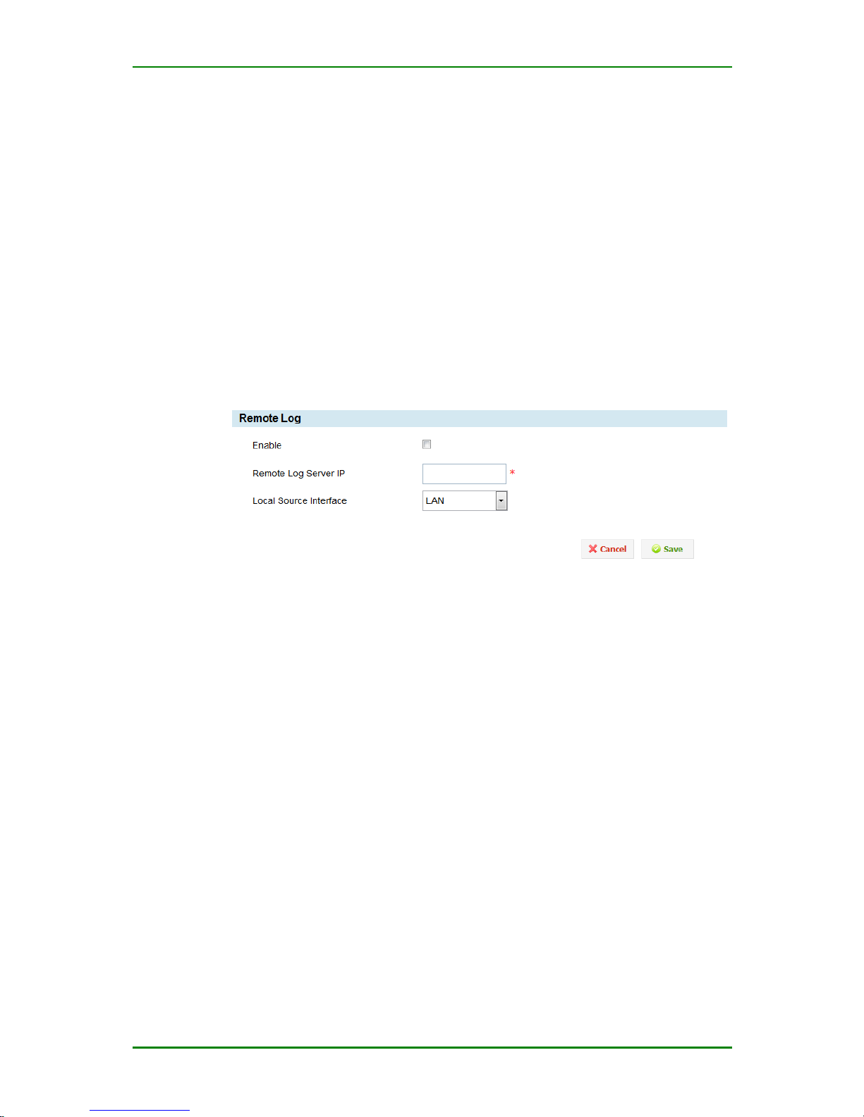
The system can send the device log information to the remote log server.
Enter System > Remote log and you can see the following configuration
interface:
Remote log configuration interface
Enable: Whether to send the device log information to the remote log
server.
Remote Log Server IP: Configure the IP address of the remote log
server.
Log Source Interface: The source address of the remote log packet is
the selected interface address.
Management Control
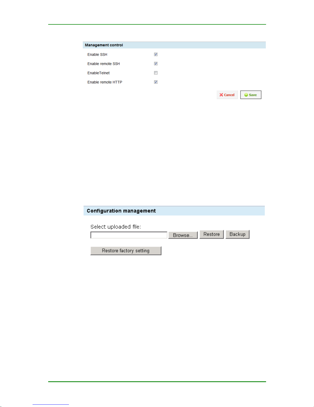
The management control function of MP1800-10 router can control
whether to enable the SSH service, Telnet service or HTTP service. Enter
System > Management Control and you can see the following
configuration interface:
Page 19
MP1800-10 3G Router User Manual
Maipu Confidential & Proprietary Information Page 19 of 95
Management control configuration interface
Configuration Management
The configuration management function of MP1800-10 provides the
backup and recovery for the user configuration. “Backup” can save the
configured parameters to the PC; “Recovery” can restore the saved
configuration parameters to the system.
1. Backup configuration
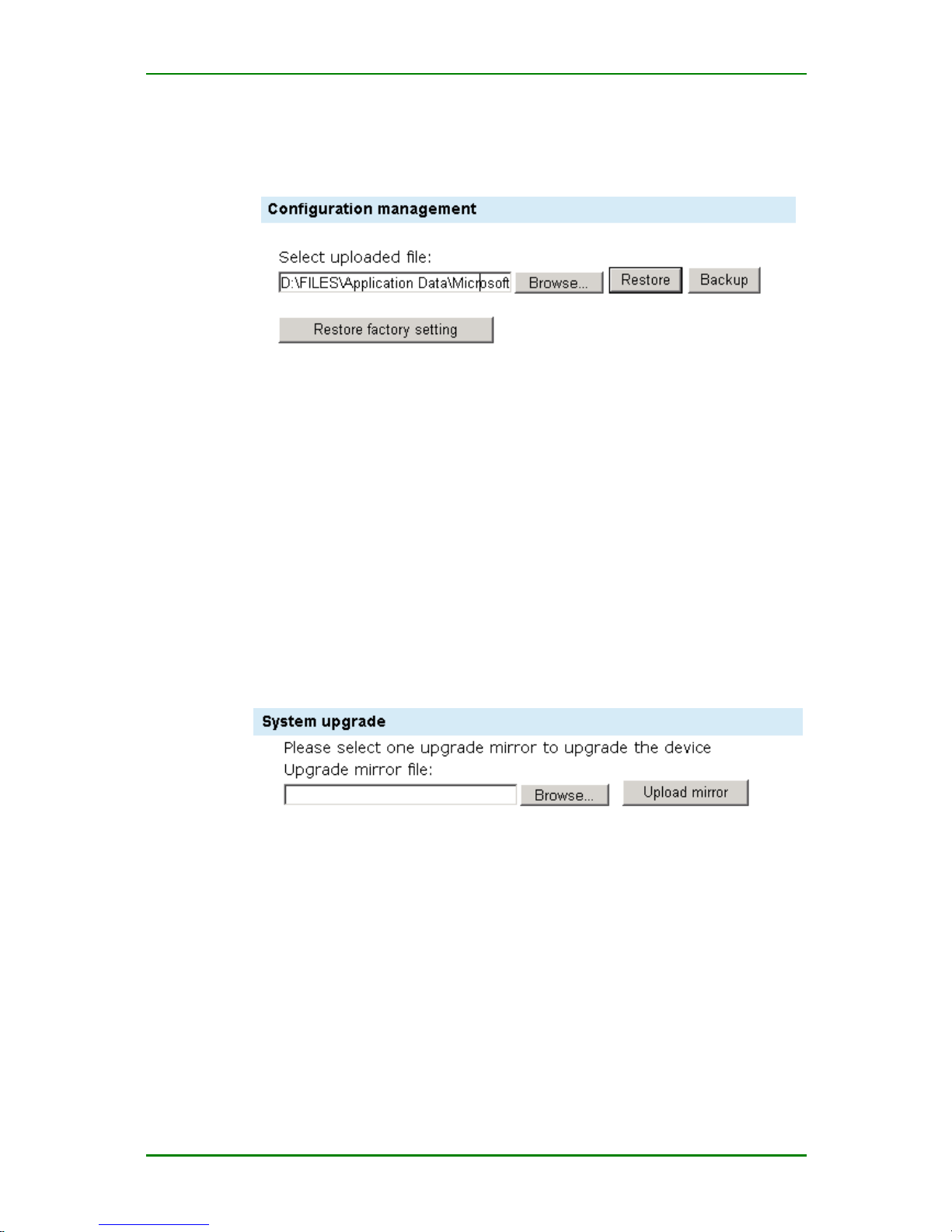
Enter System > Configuration Management and you can see the
following interface:
Backup configuration interface
Click Backup and you can back up the current user configuration of the
system.
Caution
Save the backup file to the desired host CD, avoiding being lost.
2. Recover configuration
Page 20
MP1800-10 3G Router User Manual
Maipu Confidential & Proprietary Information Page 20 of 95
When you need to restore the user configuration to the system, enter
System > Configuration Management, click Browse to select the
desired backup file, and then click Recover, as follows:
Recover configuration
3. Recover factory configuration
When you want to restore the system to the factory status, enter System
> Configuration Management, and click Restore Factory Setting.
System Upgrade
MP1800-10 router can perform the remote web upgrade. Before
upgrading, you need to ensure that you have got the target file. During
upgrading, enter System > System Upgrade and you can see the
following interface:
System upgrading interface
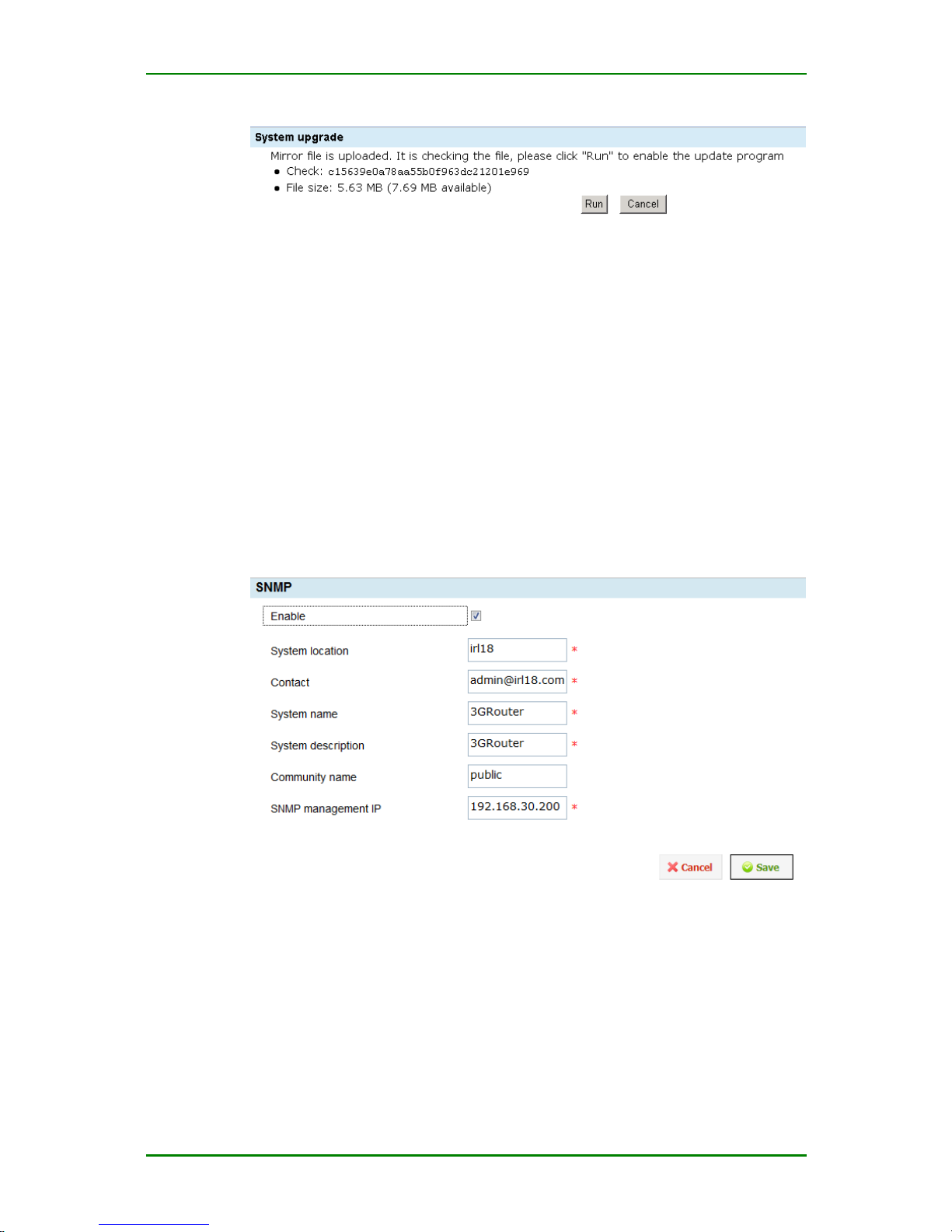
Click Browse to find the target file, click Upload Mirror, and the system
starts to upload the mirror. After uploading, you can see the following
figure:
Page 21
MP1800-10 3G Router User Manual
Maipu Confidential & Proprietary Information Page 21 of 95
Upgrading process
Click Run to start upgrading system. The upgrading is slow and you can
view the upgrade process via the upgrade process bar. After upgrading
successfully, the interface turns to the login interface automatically.
Caution
During upgrade, do not power off. Otherwise, the device cannot be used.
SNMP
When you want to configure SNMP, enter System > SNMP and you can
see the following interface:
SNMP configuration interface
Enable: Whether to enable SNMP
System location: Input the location of the router
Contact: Input the contact of the administrator of the router
System name: Input the name of the router
Page 22
MP1800-10 3G Router User Manual
Maipu Confidential & Proprietary Information Page 22 of 95
System description: Input the description of the router
Community name: Specify the community name of SNMP
SNMP management IP: Specify the server IP address to which the Trap
message of the device is sent
Prompt
The above configurations are all set to the nodes in MIB.
Modify Password
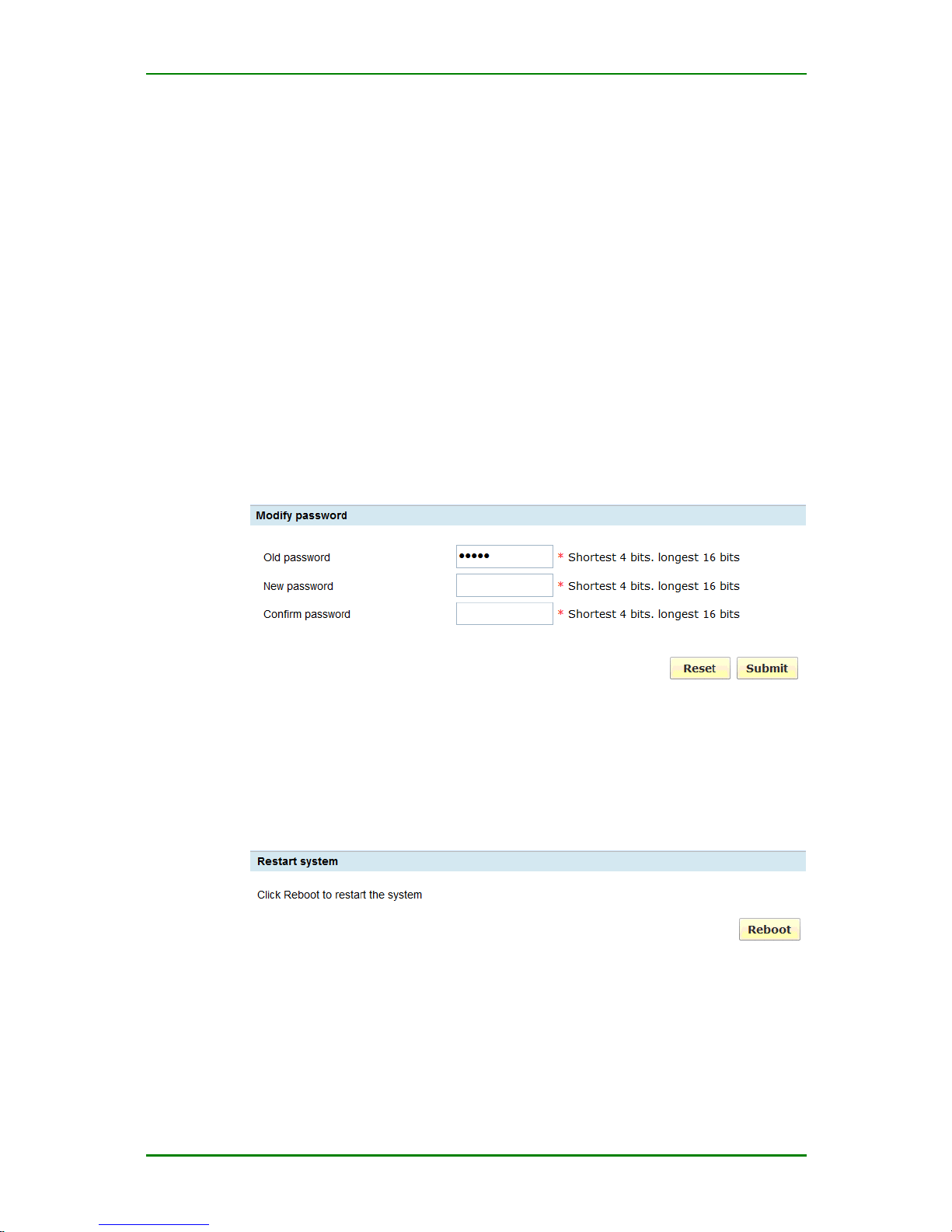
MP1800-10 router provides the authority of modifying user password.
Enter System > Modify Password and you can set the new password for
the system administrator admin, as follows:
Modify password
Restart System
When you want to restart MP1800-10 router via software, enter System
> Restart System and you can see the following interface. Click Restart.
System restarting interface
Caution
After restarting successfully, you need to re-log into the system so that
you can configure.
Page 23

MP1800-10 3G Router User Manual
Maipu Confidential & Proprietary Information Page 23 of 95
Log Out
When you want to log out the web configuration interface of MP1800-10
router, enter System > Log out.
Network
MP1800-10 router network setting includes the following functions:
Dialing interface
WAN interface
LAN interface
Forwarding mode
Dynamic domain name
Static route
Dynamic route
Get online manually
WIFI setting
Dial Interface
1. Basic Setting
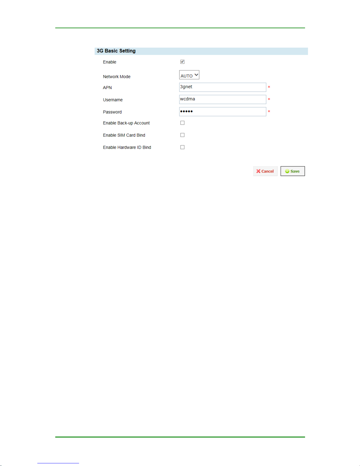
Click Network > Dial Interface > Basic Setting, and you can see the
basic configuration interface of the mobile network:
Page 24
MP1800-10 3G Router User Manual
Maipu Confidential & Proprietary Information Page 24 of 95
Basic setting of mobile network
Network mode: Set the mobile network access mode (2.5G/3G/auto
switchover);
APN: Specifies the APN (Access Point Name) of the mobile carrier;
User name: Set the user name used by dialing (you can get from the
network provider); the maximum length is 128 bits;
Password: Set the password used by dialing (you can get from the
network provider); the maximum length is 128 bits.
Enable Back-up account: Set using the standby account to dial. If
enabling the item and when the master account dialing fails, use the
standby account to dial.
Enable SIM Card Bind: Set the binding function of the SIM card. If
enabling the option, bind the IMSI code of the SIM card with the system.
When using the 3G module for the first time, record the card number. If
using other card subsequently and enabling the option, there is error.
Enable Hardware ID Bind: After enabling the function, carry the
hardware ID (hardware ID is MAC address of LAN port; the format of dial
user name is $MAC$user name) in the dial user name. LNS adopts the
hardware ID, user name, password, and IMSI to authenticate. The
function needs LNS and AAA server to cooperate.
For the common user, after completing the above basic parameter
configuration and saving, MP1800-10 router performs the wireless network
dialing connection automatically after powering on every time. It is
convenient to use.
Page 25
MP1800-10 3G Router User Manual
Maipu Confidential & Proprietary Information Page 25 of 95
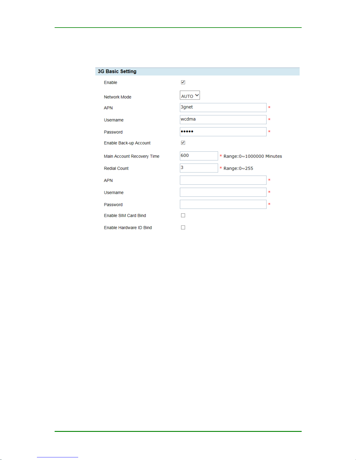
After ticking “Enable standby account”, the basic setting interface of the dial
interface is as follows:
Basic setting of mobile network
Main Account Recovery Time: After setting standby account dialing
successfully, restore the dialing interval of the master account. The unit is
minute; the default value is 600 minutes; 0 means not to restore the
master account.
Re-dial Count: Set the re-dialing times of each account. By default, it is
three times. 0 means always trying to use the master account dialing and
do not use standby account.
APN: Specifies the APN (Access Point Name) of the backup mobile carrier;
User name: Set the user name used by dialing (it can be got from the
network provider). The maximum length is 128 bits.
Password: Ser the password used by dialing (it can be got from the
network provider). The maximum length is 128 bits.
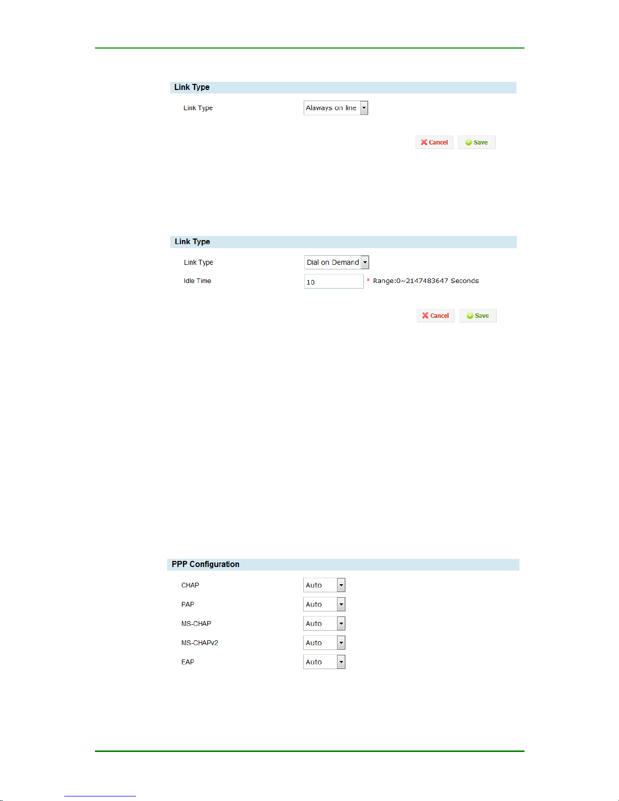
2. Link Type
Set link connection mode, including online forever and dial on demand.
Enter Network > Dial interface > Link type and you can see the
configuration interface of the link type:
Page 26
MP1800-10 3G Router User Manual
Maipu Confidential & Proprietary Information Page 26 of 95
Online forever
Always on line: Make the network connection be online forever.
Dial on demand
Dial on demand: Trigger dial when there is service data flow. If the router
is configured with the service that needs to use the 3G traffic, such as NTP,
remote log and IPSec DPD, the dial on demand function becomes invalid.
Idle time: Set the idle time of the connection; when reaching the idle
time, close the connection.
3. Advanced setting
If you are advanced user, enter Network > Dial Interface > Advanced
Setting, and you can complete the following advanced parameter
configuration:
Authentication and encryption parameters:
Authentication & encryption parameters
Page 27
MP1800-10 3G Router User Manual
Maipu Confidential & Proprietary Information Page 27 of 95
CHAP (Challenge-Handshake Authentication Protocol): It is one
encrypted authentication mode and can avoid transmit the actual
password of the user when setting up the connection. For PPP, the key
information does not need to be transmitted in the channel during the
authentication and the information switched during each authentication is
different, which can avoid monitoring attack and improve the security.
PAP: It is one simple plain text authentication mode. It is required that
the key information is transmitted in plain text via the channel, so it is
easy to be monitored and leaked by sniffer.
MS –CHAP: It is similar to CHAP. MS-CHAP is also one encryption
authentication mechanism, using MPPE-based data encryption.
MS2-CHAP: MS-CHAP version 2.
EAP: It is one expansible authentication protocol. The protocol is used by
the authentication in the point-to-point network, such as PPP. It can
support various authentication mechanisms. With the expansible
authentication protocol, any ID authentication mechanism can
authenticate the remote access connection.
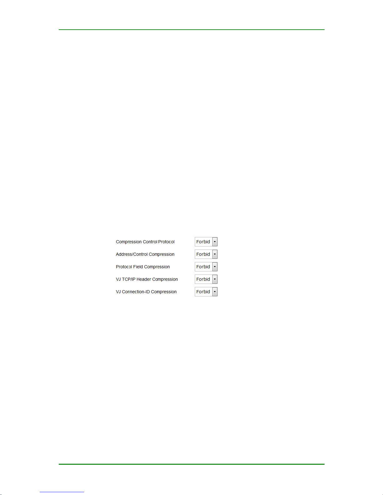
Compression and control protocol parameters
Compression & Control protocol
Compression control protocol: Responsible for the configuration on the
PPP link and negotiating which compression algorithm to adopt. And adopt
the reliable mode to identify the failure of the compression and decompression mechanism.
Address/control compression: Whether to permit PPP packet address
domain and control compression setting.
Protocol domain compression: Whether to enable the protocol domain
compression.
VJ TCP/IP header compression: Whether to permit TCP/IP data to
perform the Van Jacobson header compression.
Connection ID compression: Whether to permit the connection ID
compression.
Page 28
MP1800-10 3G Router User Manual
Maipu Confidential & Proprietary Information Page 28 of 95
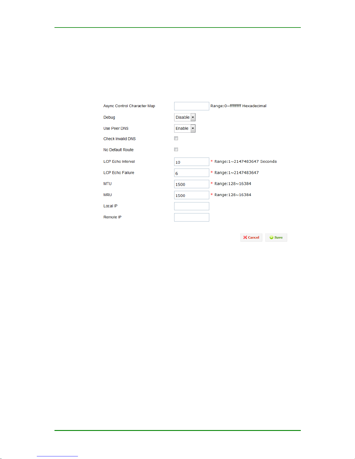
Other parameters
Other parameter setting provides you whether to permit using the peer
DNS, LCP echo interval, LCP echo failure, packet side processing, and
debug IP setting.
Other parameters
Asyn Control Character Map: The asyn control character mapping is one 32-bit
set. Each bit indicates one ASCII value, 0-31 ASCII character. Each bit with the
value 1 indicates that the corresponding control character should not be in the
PPP packet sent by the peer. The mapping table uses the hexadecimal coding
(do not need 0x). The least significant bit (00000001) indicates the character 0
and the most significant bit (80000000) indicates the character 31.
Debug: Set whether to output the details of LCP, IPCP negotiation during
PPP dialing. By default, it is disabled.
Use Peer DNS: Whether to permit using peer DNS. By default, it is
enabled.
Check invalid DNS: If ticking, detect whether the got DNS is valid. If
invalid, re-dial.
No Default Route: If ticking, do not add the default route to the dialing
interface. Otherwise, after dialing succeeds, add the default route to the
dialing interface.
LCP Echo Interval: PPP link control protocol (LCP) echo interval setting.
The value range is 1-2147483647.
Page 29
MP1800-10 3G Router User Manual
Maipu Confidential & Proprietary Information Page 29 of 95
LCP Echo Failure: PPP link control protocol (LCP) echo failure times
setting. The value range is 1-2147483647.
MTU: Maximum transmission packet size setting of MP1800-10 router on
the PPP link. Take byte as unit. For LAN, the maximum transmission unit is
1,500 bytes. The maximum packet transmitted on the PPP link can be set
smaller.
MRU: The maximum packet size received by MP1800-10 router.
Local IP: Set the local IP of MP1800-10 router when performing PPP IPCP
negotiation.
Remote IP: Set the peer IP of MP1800-10 router when performing PPP
IPCP negotiation.
WAN Interface
1. WAN interface
Ethernet-based WAN interface supports various protocols, including static IP,
DHCP and PPPoE.
Enter Network > WAN interface > WAN interface and you can see the
setting interface of WAN interface:
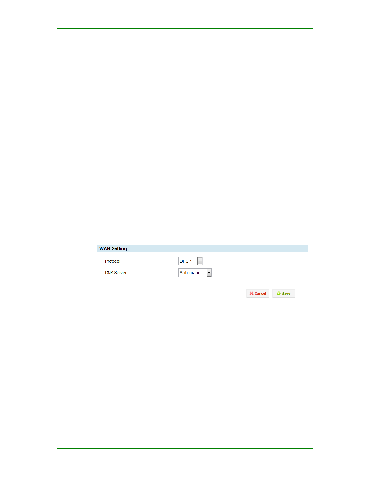
WAN interface setting
Protocol: Set the protocol used when WAN interface is connected to Internet,
including static IP, DHCP, PPPoE or disable.
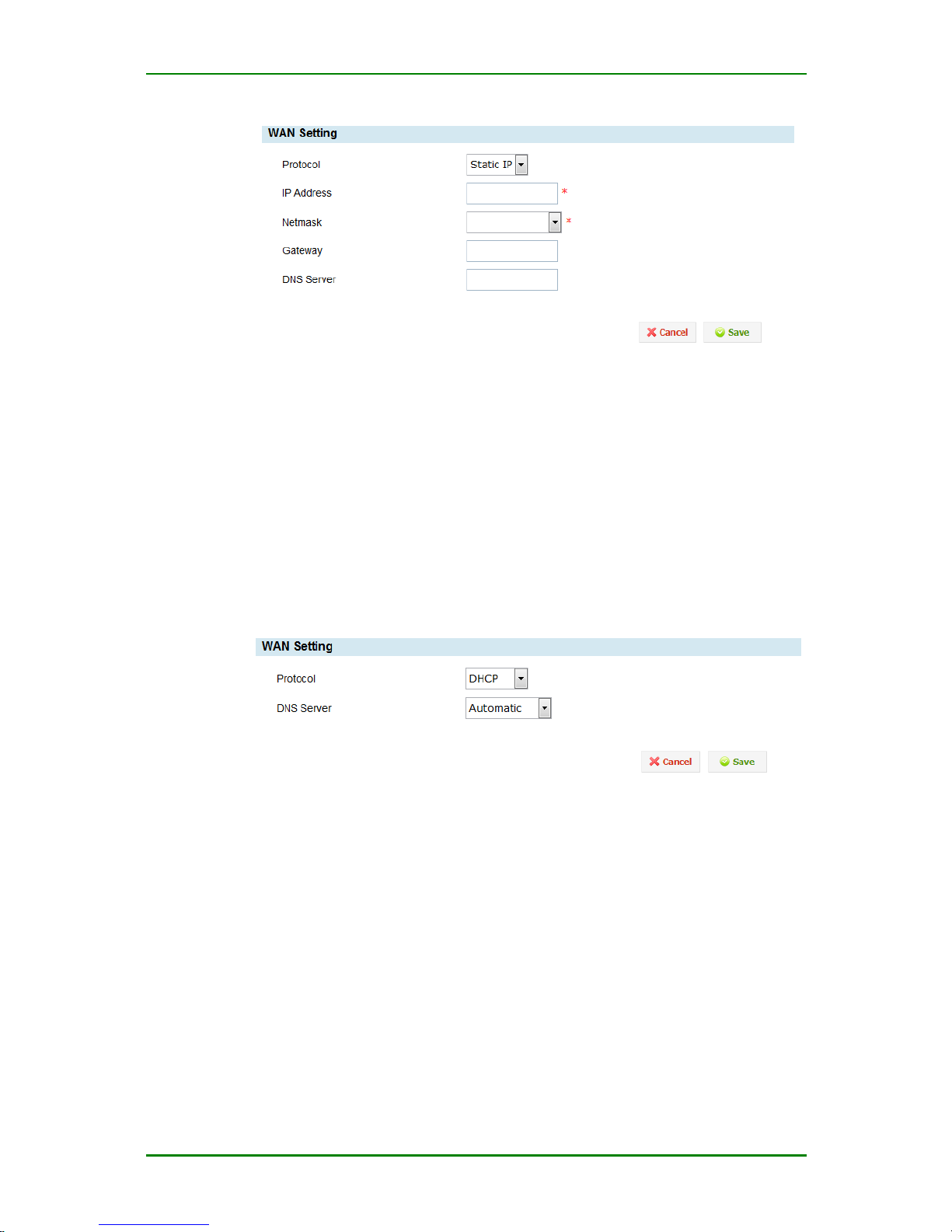
After selecting the connection mode as static IP, the setting interface of WAN
interface is as follows:
Page 30
MP1800-10 3G Router User Manual
Maipu Confidential & Proprietary Information Page 30 of 95
Static IP setting
IP address: Set the IP address of the WAN interface. It is mandatory.
Netmask: Set the subnet mask of the WAN interface. It is mandatory.
Gateway: Set the default gateway of the WAN interface.
DNS Server: Set the DNS server of the WAN interface. The DNS
server uses the IP address format. Multiple DNS servers are separated
by the blank.
After selecting the connection mode as DHCP, the setting interface of WAN
interface is as follows:
DHCP setting
DNS server: Set the DNS server of the WAN interface. The DNS server uses the
IP address format. Multiple DNS servers are separated by the blank. By
default, use the DNS server distributed by the DHCP server.
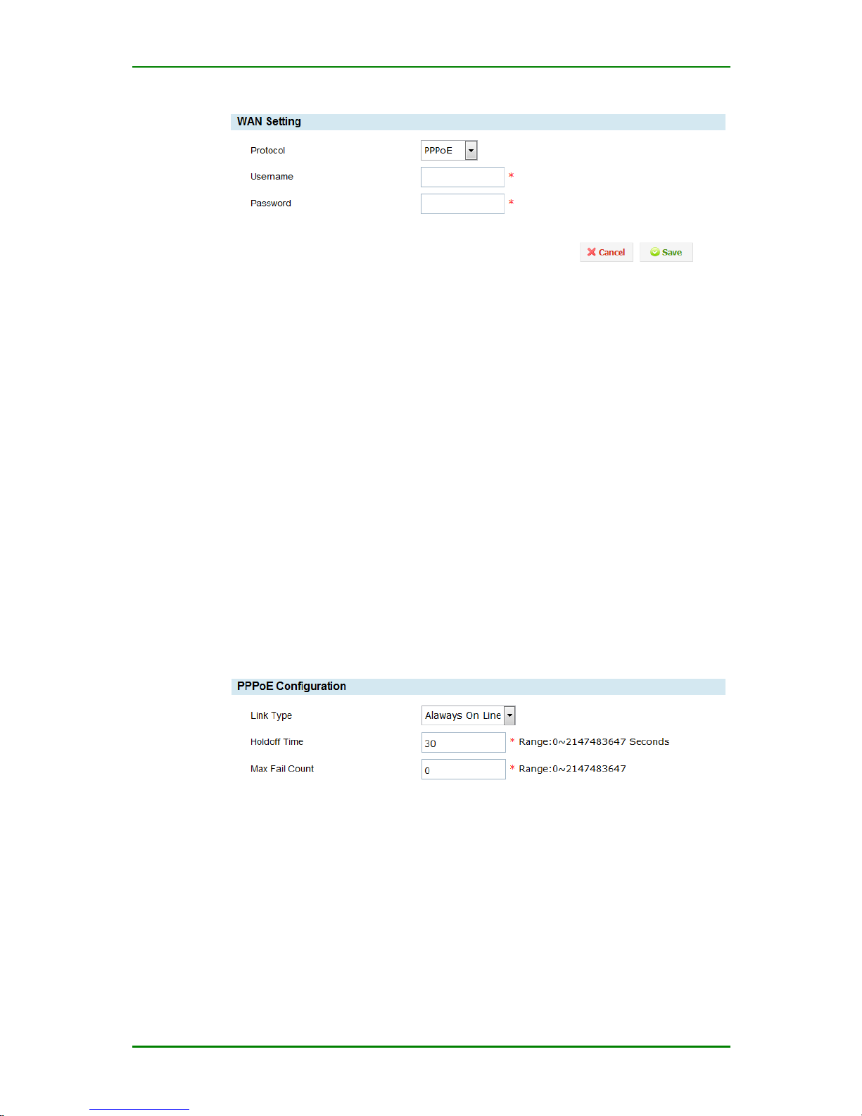
After selecting the connection mode as PPPoE, the setting interface of WAN
interface is as follows:
Page 31
MP1800-10 3G Router User Manual
Maipu Confidential & Proprietary Information Page 31 of 95
PPPoE setting
User name: Set the user name used when the WAN interface uses the PPPoE
protocol to dial.
Passsword: Set the password used when the WAN interface uses the PPPoE
protocol to dial.
When using the PPPoE protocol, you can configure other parameters by
Network > WAN interface > PPPoE advanced setting.
After selecting the connection mode as Disable, you cannot connect Internet via
Ethernet WAN interface.
2. PPPoE advanced setting
If you are advanced user, enter Network > WAN interface > PPPoE
advanced setting, and you can complete the configuration of the following
advanced parameters.
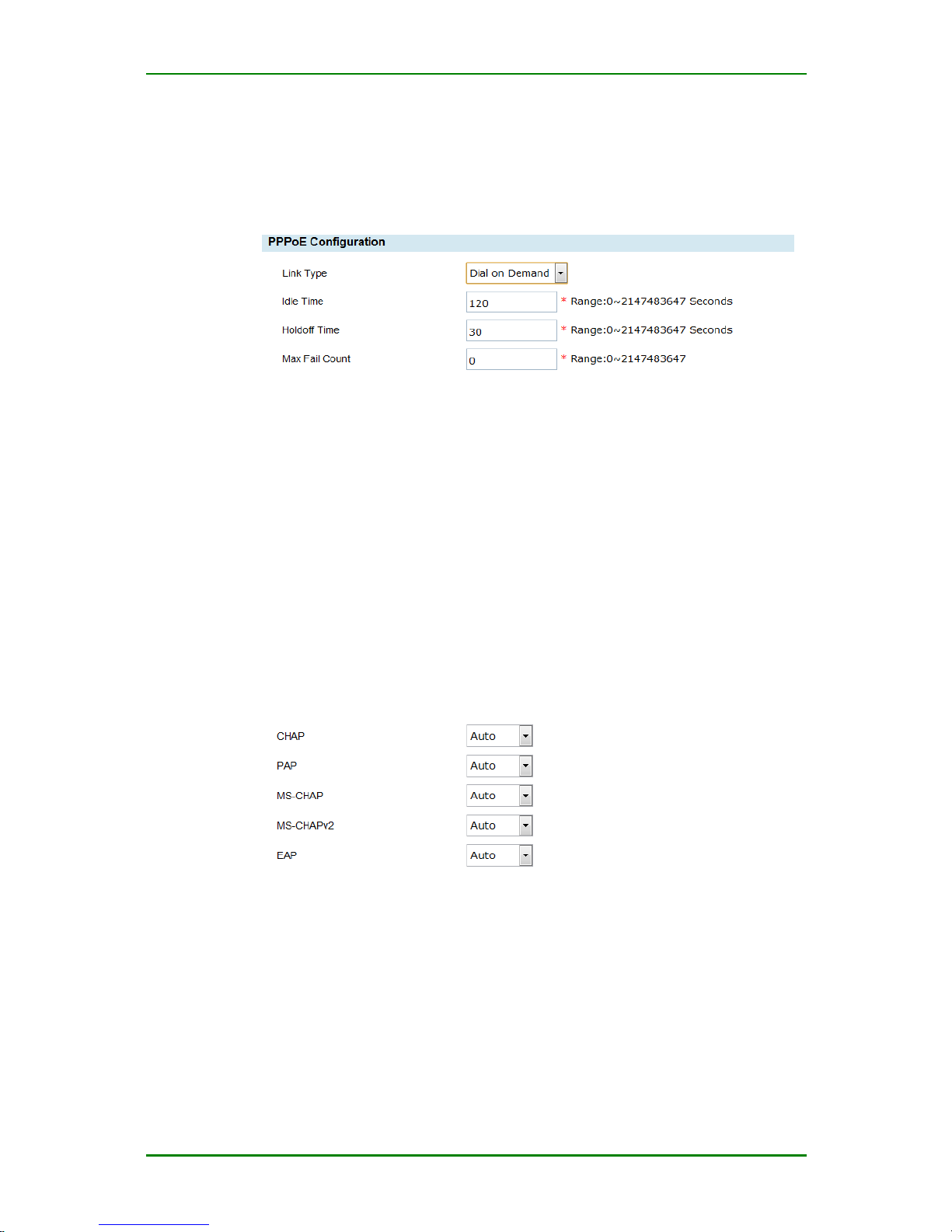
(1) Link type parameter
Forever online setting
Always online: Always try to connect Internet until reaching the maximum error
times. If connecting Internet successfully, the device is always in the online state.
When the network is disconnected, automatically re-dial.
Holdoff Time: Set the waiting time for re-dialing after dialing fails. The default
value is 30s. It is mandatory.
Page 32
MP1800-10 3G Router User Manual
Maipu Confidential & Proprietary Information Page 32 of 95
Max Fail Count: Set the maximum dialing failure times. After reaching the
maximum feature times, do not dial any more. The default value is 0 and it
means always trying. It is mandatory.
Forever online setting
Dial on demand: Traffic triggers dialing.
Idle Time: Set the idle time of connection (no any data traffic). After reaching
the idle time, disable the connection. The default value is 120s. It is mandatory.
Holdoff Time: Set the waiting time for re-dialing after dialing fails. The default
value is 30s. It is mandatory.
Max Fail Count: Set the maximum dialing failure times. After reaching the
maximum feature times, do not dial any more. The default value is 0 and it
means always trying. It is mandatory.
(2) Authentication and encryption parameters
Authentication mode configuration
CHAP (Challenge-Handshake Authentication Protocol): It is one
encrypted authentication mode and can avoid transmitting the real password of
the user when setting up the connection. As for PPP, the key information does
not need to be transmitted in the communication channel during the
authentication. Moreover, the information exchanged during each authentication
is different. It can prevent the monitor attack efficiently and improve the security.
PAP: It is one simple plain text authentication mode. It is required that the key
information is transmitted in plain text in the communication channel. Therefore,
it is easy to be listened by sniffer and leaked.
Page 33
MP1800-10 3G Router User Manual
Maipu Confidential & Proprietary Information Page 33 of 95
MS-CHAP: Similar to CHAP, MS-CHAP is one encrypted authentication
mechanism, using the MPPE-based data encryption.
MS2-CHAP : MS-CHAP protocol version 2.
EAP: It is one extended authentication protocol. The protocol is used for
the authentication in the point-to-point network, such as PPP. It supports
various authentication mechanisms. With the extendable authentication
protocol, any ID authentication mechanism can authenticate the remote
access connection.
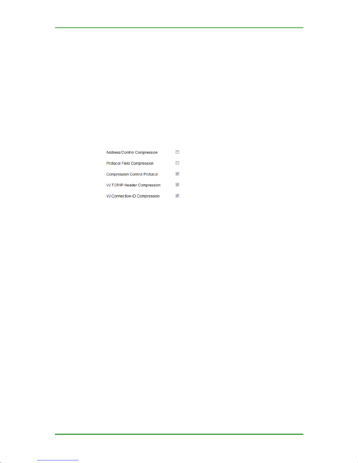
(3) Compression protocol configuration
Compression protocol configuration
Compression/Control Compression: Responsible for the configuration of the
two sides on the PPP link, negotiate which compression algorithm to adopt and
use the reliable mode to identify the failure of the compression and decompression mechanism. If ticking, it means enable.
Protocol Field Compression: Whether to permit address domain and control
domain compression in the PPP packet. If ticking, it means enable.
Compression Control Protocol: Whether to enable the protocol domain
compression. If ticking, it means enable.
VJ TCP/IP Header Compression: Whether to permit Van Jacobson header
compression for the TCP/IP packet. If ticking, it means enable.
VJ Connection ID Compression: Whether to permit the connection ID
compression. If ticking, it means enable.
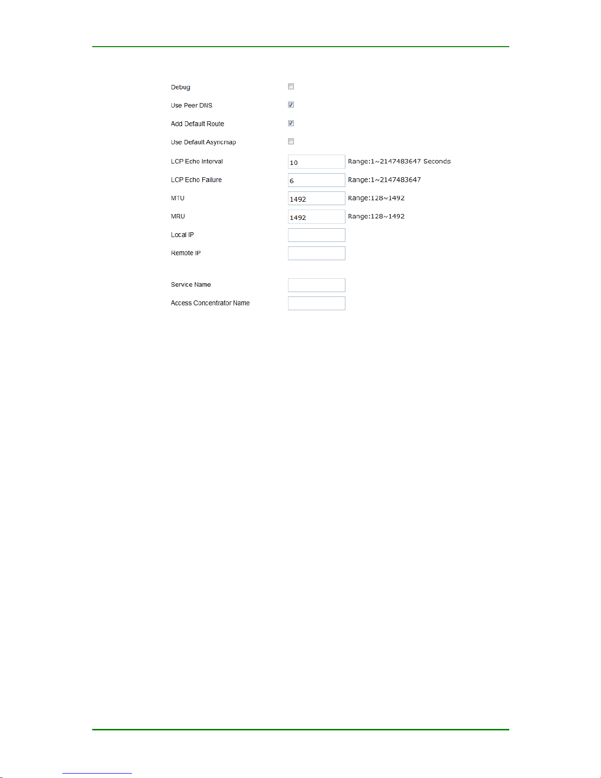
(4) Other parameters
The other parameter setting provides you whether to use the processing of the
peer DNS, LCP echo interval, LCP echo failure, and packet size and the setting of
the debugging.
Page 34
MP1800-10 3G Router User Manual
Maipu Confidential & Proprietary Information Page 34 of 95
Others
Debug: Set whether to output the details of the LCP and IPCP negotiation
during the PPP dialing. By default, it is disabled.
Use Peer DNS: Whether to permit using the peer DNS. By default, it is
enabled.
Add Default Route: If ticking, add the default route pointing to the dial
interface.
Use Default Asyncmap: Whether to enable the default asyn control
character mapping (asyncmap). By default, it is disabled.
LCP Echo Interval: Set the PPP LCP keepalive interval. The setting range
is 1-2147483647. By default, send one LCP every 10s.
LCP Echo Failure: Set the PPP LCP keepalive times. The setting range is
1-2147483647. The default value is 6 times.
MTU: Set the maximum packet transmitted on the PPP link. The unit is
byte and the maximum value is 1492.
MRU: Set the maximum packet received on the PPP link. The unit is byte
and the maximum value is 1492.
Local IP: Set the local IP requested to distribute when performing the PPP
IPCP negotiation during dialing.
Remote IP: Set the peer IP specified when performing the PPP IPCP
negotiation during dialing.
Service Name: Set the name of the service requested during the PPPoE dialing.
Page 35
MP1800-10 3G Router User Manual
Maipu Confidential & Proprietary Information Page 35 of 95
Access Concentrator Name: Set the name of the access server requested
during the PPPoE dialing.
LAN Interface
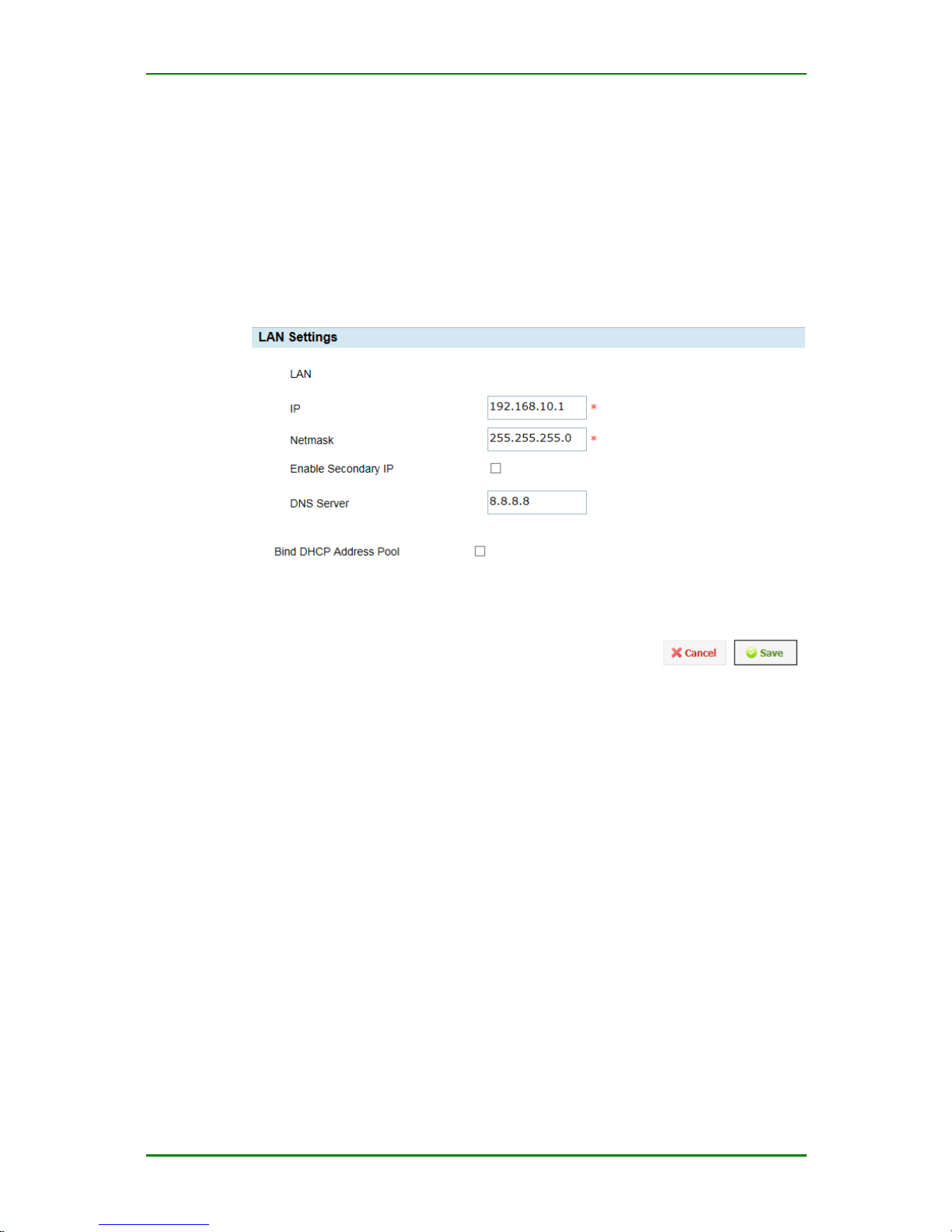
LAN interface configuration provides the configuration for MP1800-10
router Ethernet port. Enter Network > LAN interface and you can see
the following configuration interface:
LAN setting
IP: Set or modify the LAN IP address of MP1800-10 router. The default
value is 192.168.10.1. Usually, it is the gateway IP or LAN gateway of the
direct-connected computer.
Netmask: Set or modify the special IP address identifying the network
address of the LAN IP, such as 255.255.255.0.
Enable Secondary IP: Klick if you want this Interface to provide a
secondary IP address
DNS Server: Allows to specify a specific DNS Server
Bind DHCP Address Pool: Klick if DHCP Address Pool is to be bound to
this LAN Interface. If you want to configure the DHCP Address, please
disable this item.
Page 36
MP1800-10 3G Router User Manual
Maipu Confidential & Proprietary Information Page 36 of 95
Prompt
1. If you do not need to modify the LAN IP of MP1800-10 router,
you can jump over the LAN setting.
2. If you modify the factory LAN IP of MP1800-10 router, you
need to return to Chapter 3 to re-configure the computer and
re-log into MP1800-10 router.
Forwarding Mode
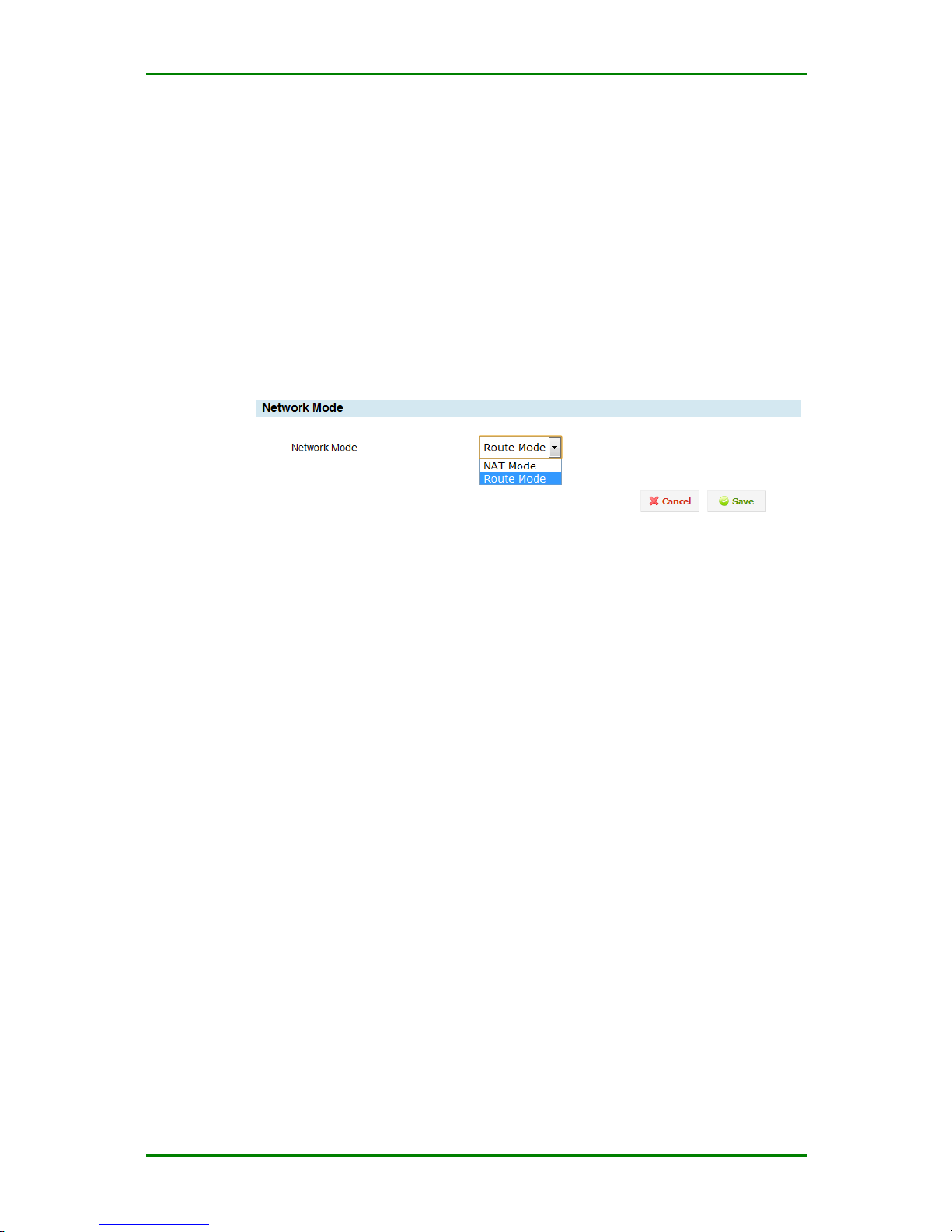
Forwarding mode is used to set the forwarding mode of the packet to be
based on route searching or IP address pretending. Enter Network >
Forwarding mode, and you can see the following configuration interface:
Forwarding mode setting
Route mode: Decide the forwarding path by searching for the system
route table.
NAT mode: Perform the source address pretending for the packet to
realize the requirement of LAN sharing one IP for accessing Internet.
Caution
In the application environment of dialing for Internet, the recommended
forwarding mode is NAT mode, which can reduce the configuration for the
route table.
Dynamic Domain Name
DDNS is short for dynamic domain system. DDNS protocol provides the
querying function between the dynamic IP and domain name. With
MP1800-10 router, you can access LAN internal mapping to the services
on the dynamic IP quickly.
Enter Network > Dynamic Domain Name and you can see the following
configuration interface:
Page 37
MP1800-10 3G Router User Manual
Maipu Confidential & Proprietary Information Page 37 of 95
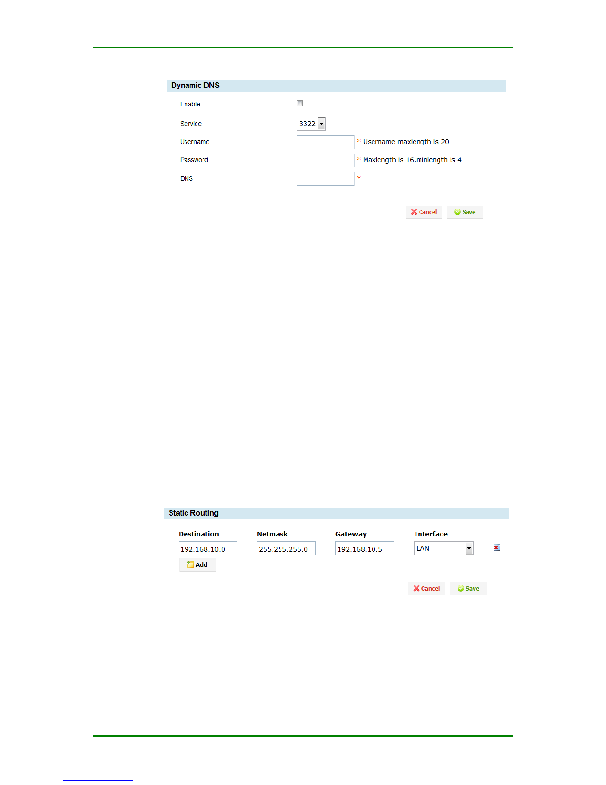
Dynamic domain name configuration interface
Enable: If ticking the item, activate DDNS. Otherwise, disable DDNS.
Service: Select DDNS service. Currently, just support 3322.
Username: User name applied from the DDNS service provider.
Password: The password applied from the DDNS service provider.
DNS: The DNS domain name set by the DDNS service provider.
Static Route
Static route can confirm the external route for the packet sent out. When
the router network and the target access network have multiple routers or
subnets, you need to set the static route so that different subnets can
communicate with each other.
Enter Network > Static route and you can see the following
configuration interface:
Interface for adding static route
Destination: Set the destination address of the static route, such as
192.168.0.1;
Netmask: Set the subnet mask;
Page 38

MP1800-10 3G Router User Manual
Maipu Confidential & Proprietary Information Page 38 of 95
Gateway: Set the next-hop IP address of the static route, that is, the port
address of the neighboring router.
Interface: Specify the interface on which the static route functions.
Click and you can delete the corresponding static route.
Caution
1. After adding route information, you should click Save to make
the device valid; before saving, do not switch to other
interface.
2. When the destination address is set as one IP, the subnet mask
should be set as 255.255.255.255. Otherwise, the system
calculates one network address automatically according to the
subnet mask.
3. If you want to add route information, click Add to add the static
route.
4. If selecting Black hole for interface, the one is the black hole
route and the packets matching the route are dropped directly.
5. When the dial interface and Ethernet WAN interface are up, add
the default route automatically. Do not need to add in the static
route.
Dynamic Route
MP1800-10 router supports RIP dynamic route. Enter Network >
Dynamic Route and you can perform the RIP dynamic route
configuration, as follows:
1. Dynamic route
Page 39
MP1800-10 3G Router User Manual
Maipu Confidential & Proprietary Information Page 39 of 95
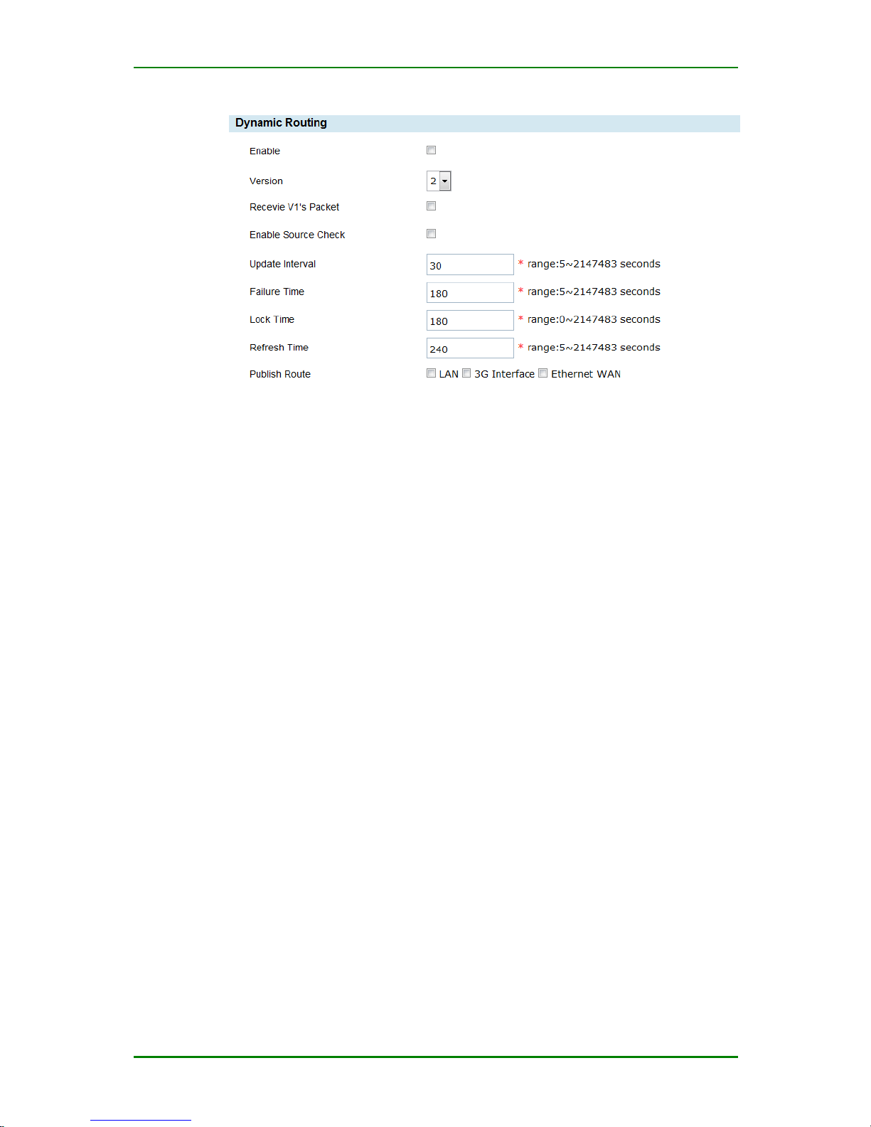
Dynamic route configuration interface
Enable: Whether to enable the RIP service;
Version: Select the RIP version, that is, RIPv1 and RIPv2.
Receive V1’s packet: When selecting RIPv2, select whether to receive
RIPv1 packets.
Enable Source Check: Select whether to detect the source address of
the point-to-point interface. By default, it is disabled.
Update Interval: Update time of RIP route, the interval of sending the
route information.
Failure time: Set the invalid interval of the route information. If not
receiving update packets after exceeding the time, set the route
information unavailable, but do not clear the route information.
Lock time: Set the locking time of the route information. The lock time is
to prevent the route loop.
Refresh time: The time of clearing the route information. When the route
entry enters the invalid state, enable the refresh timer. If not receiving the
update packets after exceeding the time, clear the related route
information.
Publish Route: Tick the desired interface. If not ticking, the interface
does not send or receive the route update information.
2. Neighbor
Enter Network > Dynamic route, as follows:
Page 40
MP1800-10 3G Router User Manual
Maipu Confidential & Proprietary Information Page 40 of 95
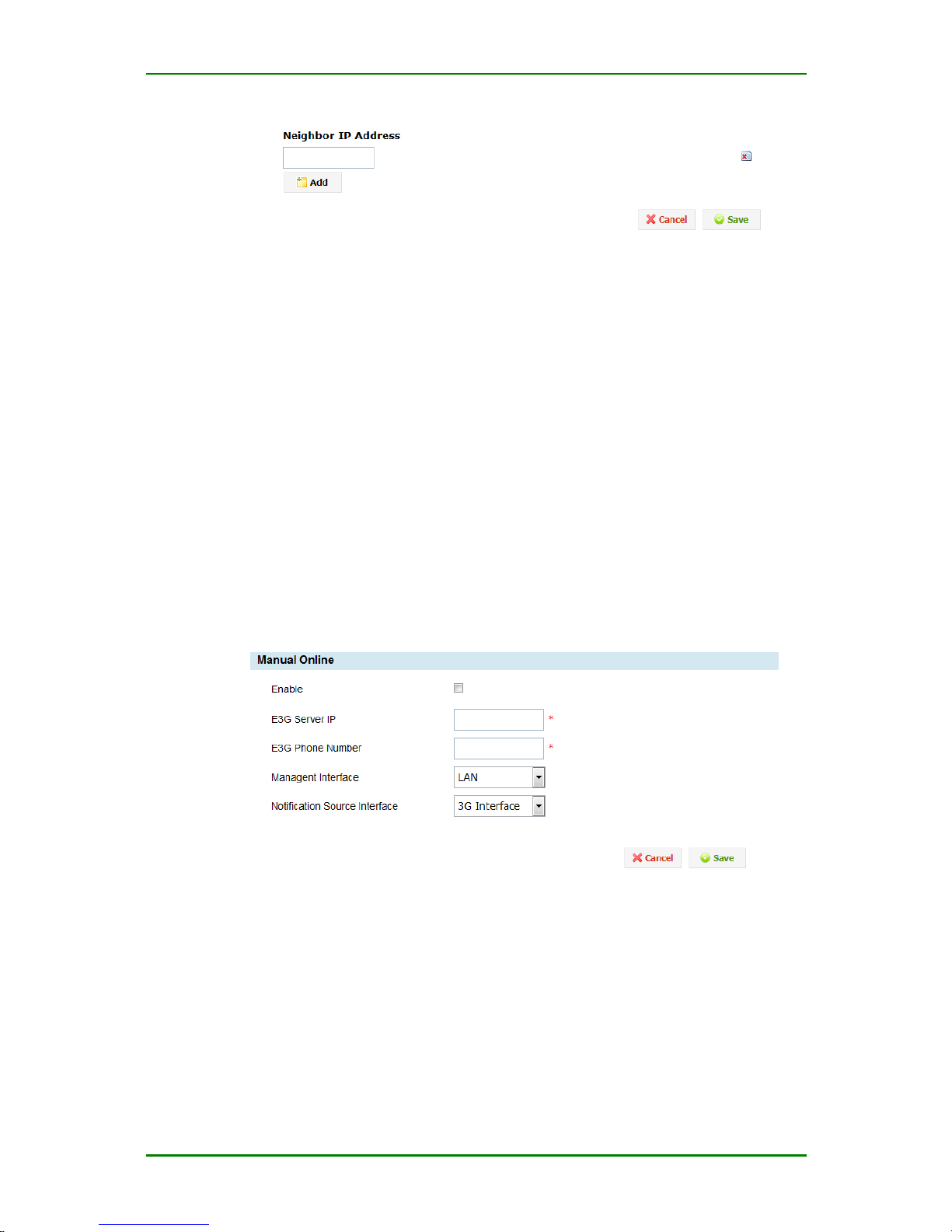
Neighbor node configuration interface
Neighbor IP Address: Set the neighbor node of the RIP route. When RIP
updates the route information every time, send the update to the host in
the unicast mode.
Caution
After adding the neighbor information, click Save to make the device
valid. Before saving, do not switch to other interface.
Manual Online
MP1800-10 router already knows the IP address of the E3G server and the
telephone number of the short message gateway. E3G server can manage
the device via the traditional mode of delivering the configuration and also
can let the E3G server to manage via the manual online.
Enter Network > Manual online to see the following configuration interface:
Manual online configuration interface
E3G Server IP: The IP address of the E3G server
E3G Phone number: The telephone number of the E3G server short
message gateway
Management interface: The interface used when the E3G server
accesses the device. It can be LAN port or dial interface.
Page 41
MP1800-10 3G Router User Manual
Maipu Confidential & Proprietary Information Page 41 of 95
Notification Source Interface: The source interface used when the
device sends the register, keepalive and alarm information to the E3G
server. It can be LAN port or dial interface.
Cautions
1. For the using of E3G management interface, usually select LAN
port when using the IPSec tunnel, that is, let the E3G server
manage the device via the tunnel; when not using the IPSec
tunnel and the 3G interface can be accessed, you can select
Dial interface.
2. For the using of the device report interface, the device
reports the information via the 3G dial interface as the
source interface; use LAN port as the report source
interface of the device so that the user can clearly
understand the IP segment used by the device. It is
convenient for the user to plan and manage the network.
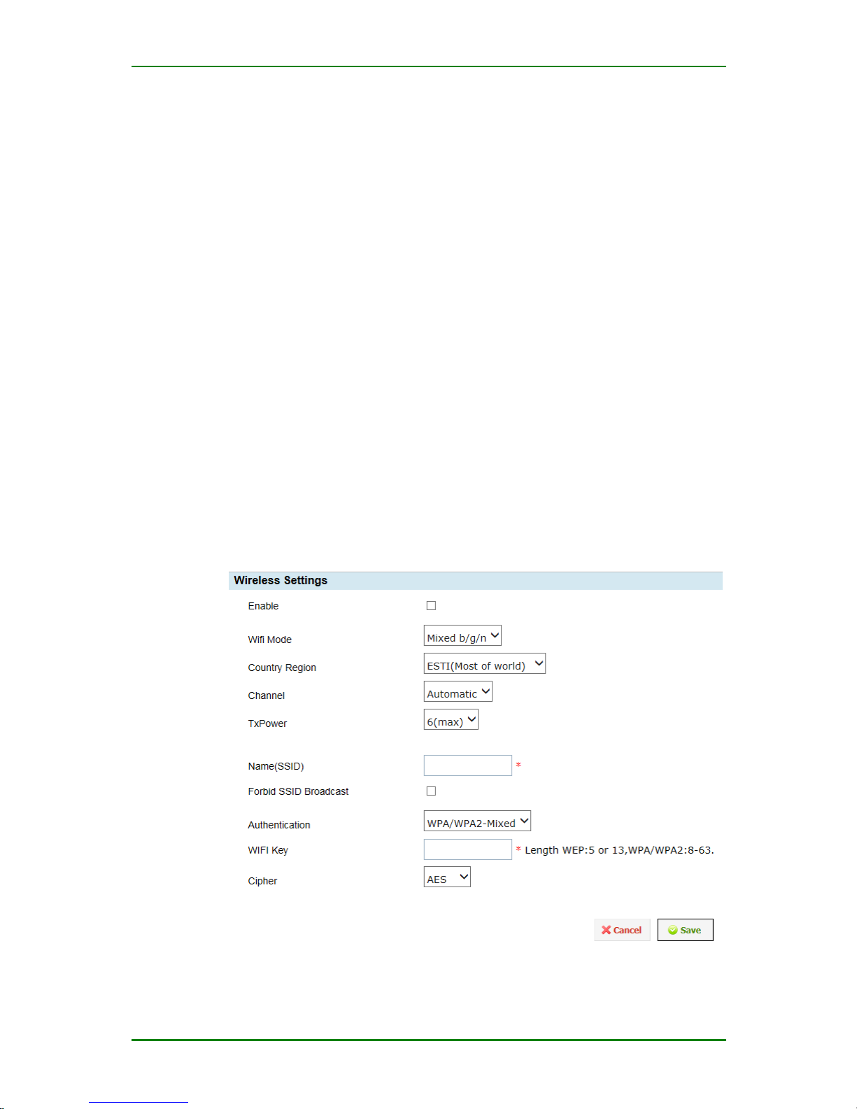
WIFI Setting
WIFI of MP1800-10 router supports the 802.11b/g/n mode and
Open/WEP/WPA/WPA2 security mode. For the configuration, enter
Network > WiFi setting and the configuration interface is as follows:
Netmask: Set or modify the special IP address identifying the network
address of the LAN IP, such as 255.255.255.0.
WiFi setting
Page 42

MP1800-10 3G Router User Manual
Maipu Confidential & Proprietary Information Page 42 of 95
Enable: Whether to enable the WiFi function. If ticking, it is enabled.
WiFi Mode: Set the WiFi work mode. You can select b mode, g mode, n mode,
mixed b/g, mixed g/n, and mixed b/g/n.
Country Region: Select the Country/Region the router is being used in. Different
countries have different regulations. Options are:
- ETSI (Most of World)
- FCC (North America)
- TELEC (Japan)
- MOC (Israel Outdoor)
Channel: Set the WiFi work channel. You can select auto or specify one
channel.
TxPower: Select the strength of the signal to be emitted
Name (SSID): Set the access point name of the wireless network.
Forbid SSID broadcast: After ticking, the SSID is not broadcast.
Authentication: Select the security mode of the wireless network. You can
select OPEN, WEP, WPA, WPA2 and WPA/WPA2 mixed. OPEN means not
encrypting. The WEP encrypted password comprises 5 or 13 ASCII
characters; the length of the WPA, WPA2 and WPA+WPA2 encrypted
password is 8-63. Set the encryption algorithm of WPA, WPA2, WPA/WPA2
mixed encrypting mode. You can select AES, TKIP, and AES+TKIP mixed.
By default, it is AES.
WIFI Key: Sets the key (password) to access the WLAN AP
Cipher: Select the encryption method for the transmitted payload. The options
are:
- AES
- TKIP
- AES+TKIP mixed.
Service
The service functions of MP1800-10 router include:
DHCP setting
Hot backup
Page 43
MP1800-10 3G Router User Manual
Maipu Confidential & Proprietary Information Page 43 of 95
AAA configuration
802.1x authentication
PIN code management
Regular online and offline
Disconnection detection
Multi-WAN port service
DHCP Setting
1. DHCP server
DHCP (Dynamic Host Configuration Protocol) is used to distribute the
dynamic IP address to the network host, so as to make the fussy
configuration become simple and easy. Especially for the large LAN IP
configuration, using DHCP service can reduce the workload of the network
management staff greatly.
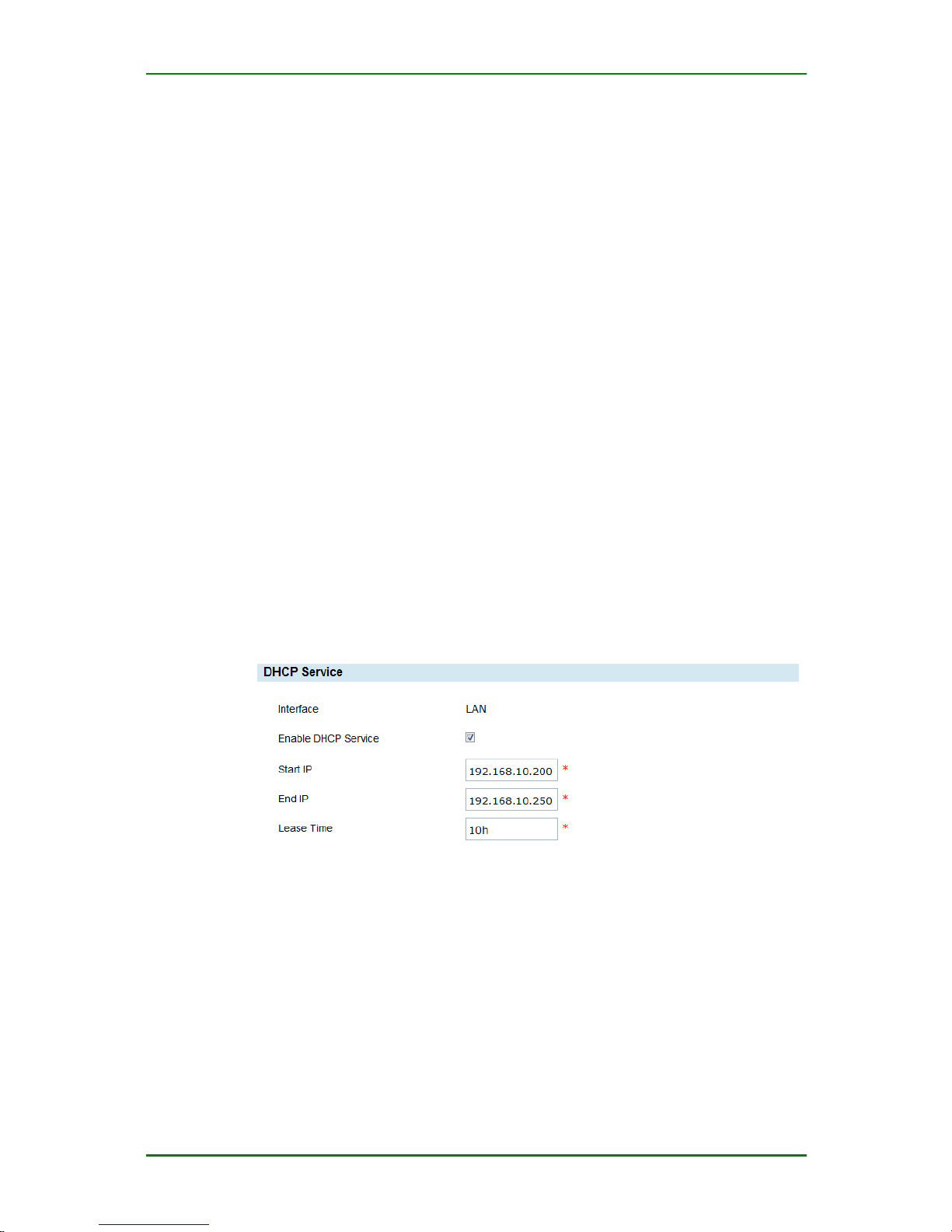
MP1800-10 router is inbuilt with DHCP server, letting it provide the
dynamic IP distributing service for your LAN. Enter Service > DHCP
Setting and you can see the following configuration interface:
DHCP setting interface
Enable DHCP service: If ticking the item, enable the DHCP service.
Otherwise, disable the DHCO service.
Start IP: The set start address should be in the same network as the IP
address of LAN port, and cannot be the broadcast address or LAN port
address.
End IP: The set end address should be in the same network as the IP
address of the LAN port, and cannot be the broadcast address or LAN port
address.
Page 44
MP1800-10 3G Router User Manual
Maipu Confidential & Proprietary Information Page 44 of 95
Lease Time: Set the keeping time of one IP address. The minimum value
is 2 minutes; the unit is h or m or s.
Prompt
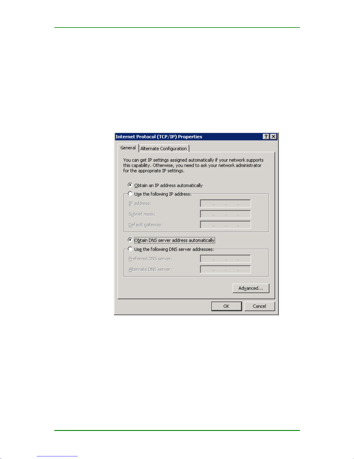
When applying the DHCP service, it is required to enable the “Auto get IP
address” function of the client host.
For the enabling of the “auto get IP address” of other kinds of client hosts,
refer to the using instruction of the device.
Setting of auto get IP address
2. Statics IP Mapping
“Static IP mapping” is the IP-MAC map setting, that is, the binging setting
of the IP address and MAC address. You can bind the IP address with the
adapter physical address (MAC) of the network device to distribute the IP
address for the LAN device to connect Internet. This not only saves the
work time, but also protects the LAN from being affected by some virus
(such as ARP proofing).
Enter Service > DHCP Setting, as follows:
Page 45

MP1800-10 3G Router User Manual
Maipu Confidential & Proprietary Information Page 45 of 95
Setting of auto get IP address
MAC Address: Set the MAC address of the static IP host, such as
00:50:56:C0:00:08.
IP Address: Set the distributed static IP address. The IP address should
be in the same network as the IP address of the LAN port and cannot be
the broadcast address or LAN port address.
Caution
After adding the static IP mapping information, click Save to make the
device valid. Before saving, do not switch to other interface.
Prompt
“Static IP mapping” also requires the client host to enable the “auto get IP
address” function.
Hot Backup
“Hot backup” means that when MP1800-10 router halts, it can turn to the
standby router directly, so as to continue the normal work.
Enter Service > Hot backup and you can see the following configuration
interface:
Page 46
MP1800-10 3G Router User Manual
Maipu Confidential & Proprietary Information Page 46 of 95
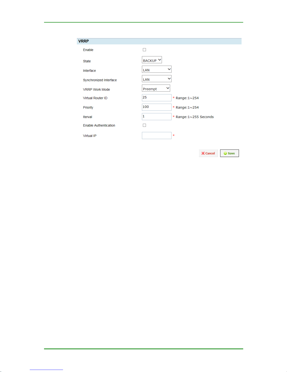
Hot backup configuration interface
Enable: Whether to enable the VRRP function.
State: Specify the state of this interface, MASTER or BACKUP
Interface: Load balance work interface (it is LAN port).
Synchronized Interface: The communication interface of the VRRP
broadcast packets (usually, it is set as LAN port).
VRRP Work Mode: Specify the VRRP work mode as PREEMPT or NONPREEMPT
Virtual Router ID: Specify the virtual router ID of this device.
Priority: The one with the highest priority becomes the master router.
Interval: The interval of sending the VRRP packets. By default, it is set as
1s.
Enable Authentication: Enable the password Authentication for VRRP
Authentication type: The authentication mode of the packets exchanged
between the master router and the standby router (group). The settings of
the master and standby routers (group) should be consistent (PASS is the
un-encrypted plain text authentication mode/AH is the encrypted
authentication mode).
Authentication password: The settings of the master and standby
routers should be consistent.
Page 47
MP1800-10 3G Router User Manual
Maipu Confidential & Proprietary Information Page 47 of 95
Virtual IP: The external virtual IP address provided by the master and
standby routers (group), as the default service gateway of the terminal
(the settings between the master and standby routers (group) should be
consistent).
AAA Configuration
The AAA module of MP1800-10 router provides the log authentication
service, including serial port, web, Telnet, and SSH.
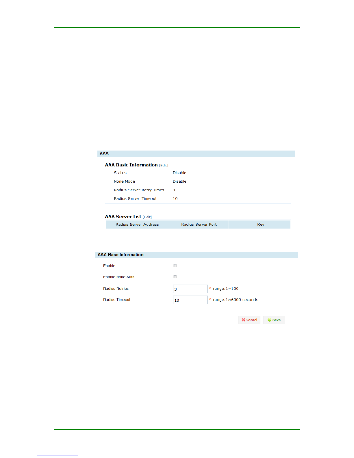
Enter Service > AAA Configuration and you can see the following interface:
AAA configuration interface
AAA basic configuration interface
Enable: Whether to enable the AAA authentication function.
Enable None Auth: When it is impossible to interact with all Radius
servers, pass the authentication automatically.
Radius Retries: The re-try times before initiating the authentication to
the next Radius server.
Page 48
MP1800-10 3G Router User Manual
Maipu Confidential & Proprietary Information Page 48 of 95
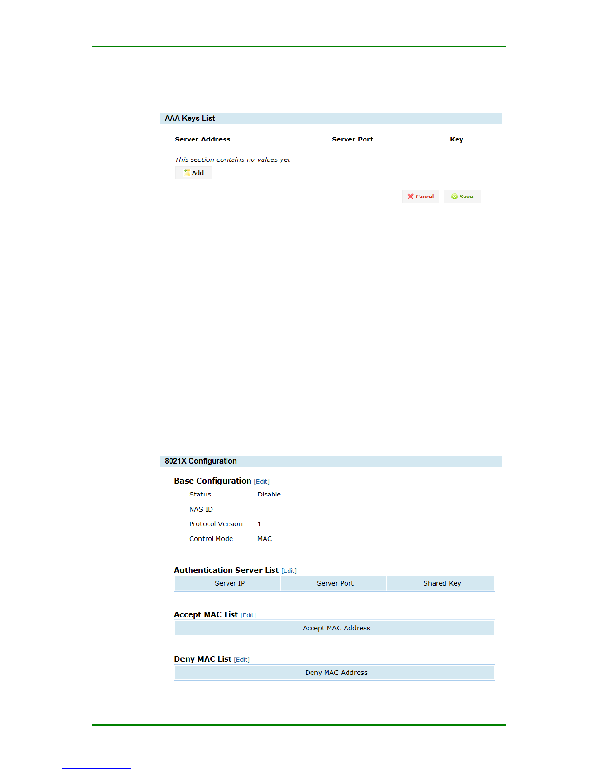
Radius Timeout: The time of waiting for the response of the Radius
server; the unit is s.
AAA server key configuration list
Server Address: The address of the Radius server.
Server Port: The port of the Radius server;
Key: The key when the Radius server interacts with the client.
802.1x Authentication
The 802.1x protocol is C/S-based access control and authentication
protocol. It can limit the un-authorized user/device from accessing
LAN/WLAN via the access port. Before getting the services provided by the
switch or LAN, 802.1x authenticates the user/device connected to the
switch. Before passing the authentication, 802.1x just permits EAPoL
(LAN-based extended authentication protocol) data to pass the switch port
connected to the device. After passing the authentication, the normal data
can pass the Ethernet port smoothly.
Page 49
MP1800-10 3G Router User Manual
Maipu Confidential & Proprietary Information Page 49 of 95
802.1x main configuration interface
Base Configuration: The basic configuration of 802.1x, such as enable,
protocol version, and access control mode.
Authentication Server List: You can configure multiple authentication
servers. When one authentication server fails, the time of switching to the
next authentication server is 6s.
Accept MAC List: Configure the accepted MAC address. The host in the
list can access the network resources without authentication.
Deny MAC List: Configure the refused MAC address. The host in the list
cannot access network resource without passing authentication.
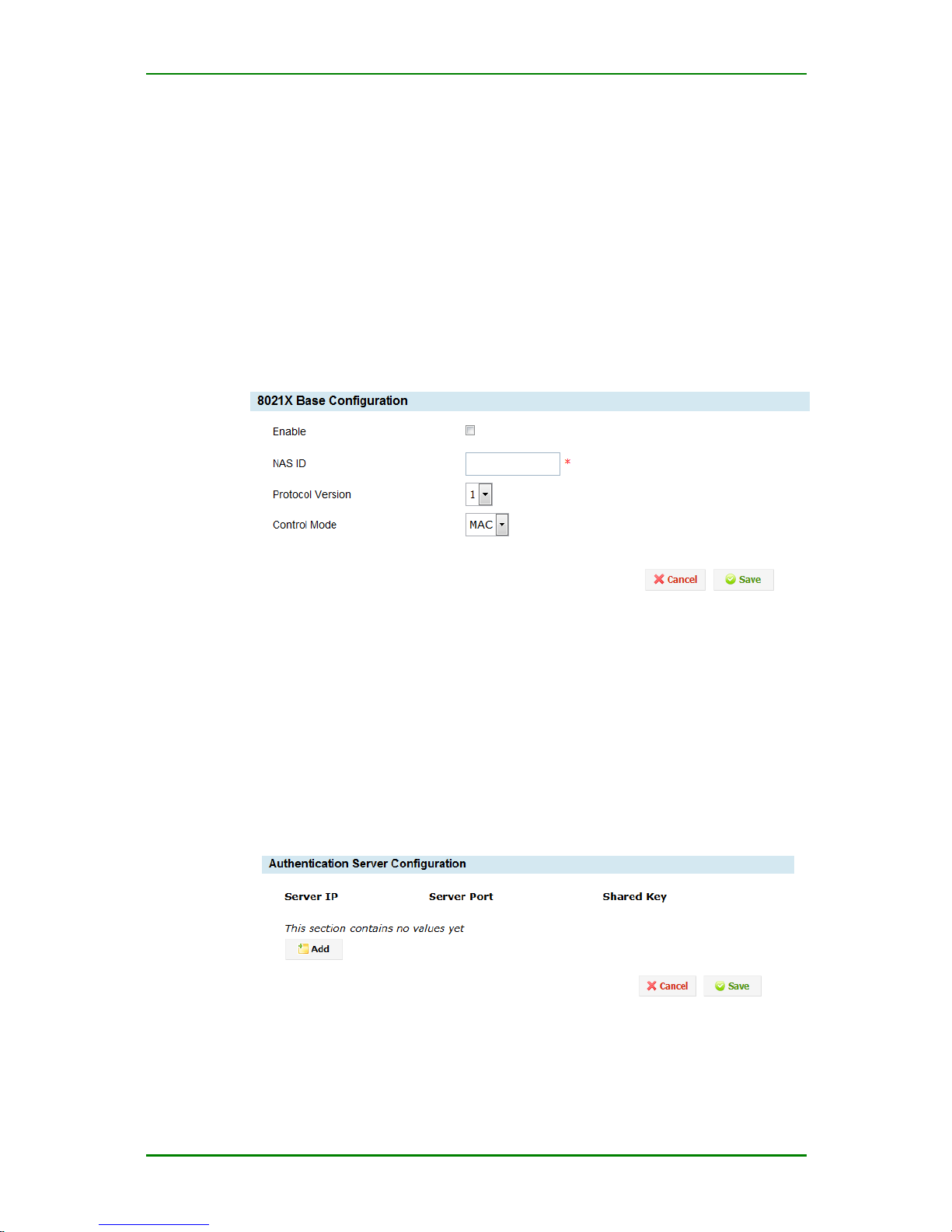
Basic configuration of 802.1x authentication
Enable: If ticking, enable the 802.1x authentication.
NAS ID: The ID of the RADIUS client.
Control Mode: Set the 802.1x access control mode, including port (port-
based) and mac (MAC-based) access control mode. In the port mode, as
long as one port passes authentication, all devices of the port can access
the network resources via the port. In mac mode, each device cannot
access the network resources unless passing the authentication.
Authentication server configuration interface
Server IP: Configure the IP address of the authentication server.
Page 50
MP1800-10 3G Router User Manual
Maipu Confidential & Proprietary Information Page 50 of 95
Server port: Configure the port of the authentication server. RFC2058
port is 1645 and RFC2866 port is 1812 (it is also the most general port.
Usually, it is configured as 1812).
Shared key: Configure the share key of the server. It should be consistent with
the configured share key of the server.
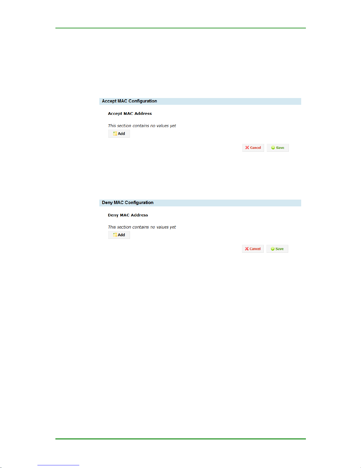
Accept MAC address configuration interface
Accept MAC address: Configure the accepted MAC address. The MAC address
can directly access the network resources without authentication.
Deny MAC address configuration interface
Deny MAC address: Configure the denied MAC address. The MAC
address cannot pass the authentication or access the network resources.
PIN Code Management
PIN code (Personal Identification Number) is the personal identifying code
of the SIM card.
PUK (PIN Unblocking Key) comprises one group of 8 digital numbers. It is
set when the SIM card is delivered from the factory. One SIM card
corresponds to one unique PUK code and cannot be modified.
“PIN code management” means that MP1800-10 router manages the PIN
code of the SIM card, including enabling or disabling PIN code protect and
modifying the PIN code and PUK code un-blocking, so as to improve the
security of the SIM card.
Caution
Page 51
MP1800-10 3G Router User Manual
Maipu Confidential & Proprietary Information Page 51 of 95
When using the management function of the PIN code, 3G dialer is
disconnected automatically.
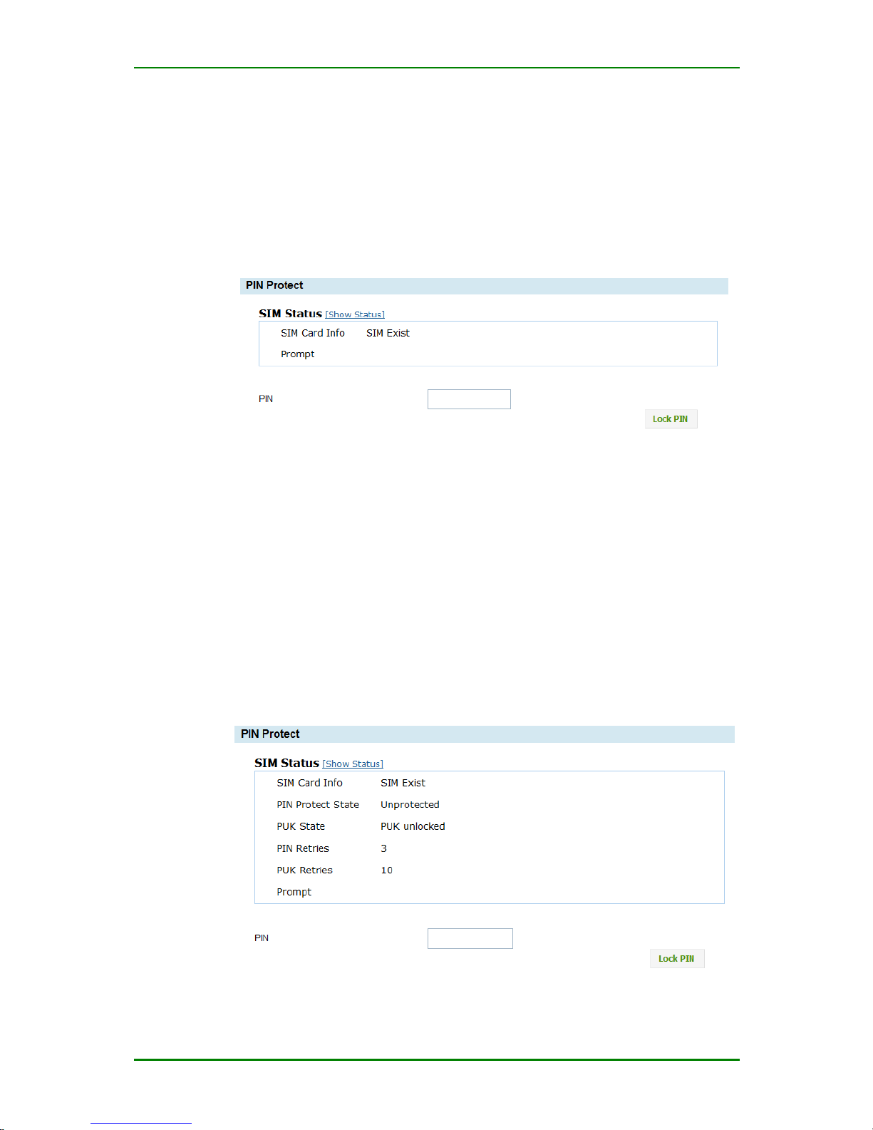
Enter Service > PIN code management > PIN code protect and you
can enable or disable the PIN code protect.
The configuration interface of enabling the PIN code protect is as follows:
Configuration interface of enabling PIN code protect
Show status: Query the current status of the SIM card, including PIN
code protect status, PIN code remaining input times, and remaining input
times of PUK code.
PIN: The PIN code is the personal identification code, comprising 4-8
digitals.
Enable protect: Enable the PIN code protect. After enabling the PIN code
protect, the system automatically records the valid PIN code. Use the PIN
code when dialing.
Click Show Status and the PIN code protect interface is as follows:
Page 52
MP1800-10 3G Router User Manual
Maipu Confidential & Proprietary Information Page 52 of 95
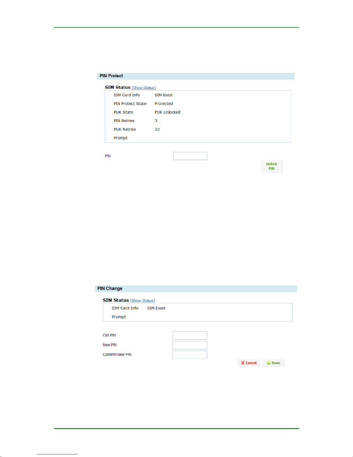
Configuration interface of enabling PIN code protect
The configuration interface of disabling the PIN code protect is as follows:
Configuration interface of disabling PIN code protect
Show status: Query the current status of the SIM card, including PIN
code protect status, PIN code remaining input times, and remaining input
times of PUK code.
PIN: The PIN code is the personal identification code, comprising 4-8
digitals.
Enable protect: Enable the PIN code protect.
Enter Service > PIN code management > Modify PIN code and you
can modify the PIN code. The configuration interface is as follows:
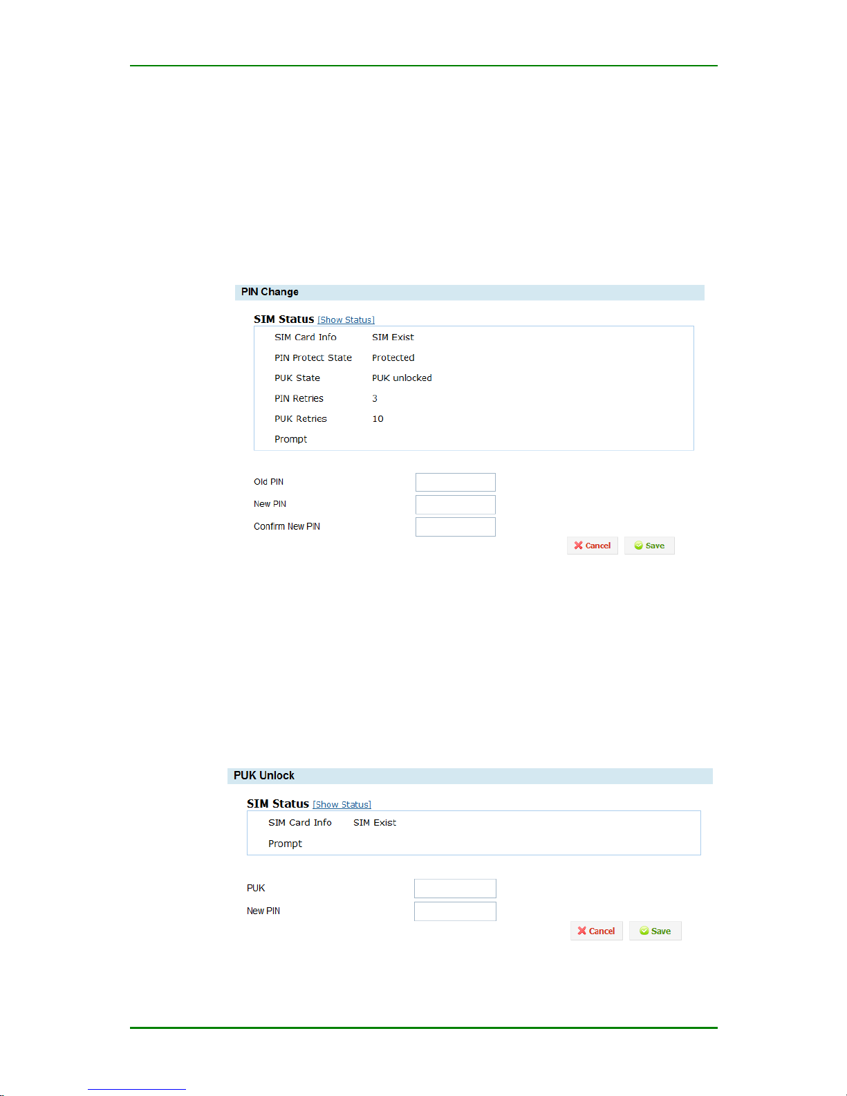
The interface of modifying the PIN code
SShow status: Query the current status of the SIM card, including PIN
code protect status, PIN code remaining input times, and remaining input
times of PUK code.
Page 53
MP1800-10 3G Router User Manual
Maipu Confidential & Proprietary Information Page 53 of 95
Old PIN: It comprises 4-8 digitals.
New PIN: It comprises 4-8 digitals.
Confirm new PIN: It comprises 4-8 digitals.
Click Show Status and the interface for modifying the PIN code is as
follows:
Interface for modifying the PIN code
After modifying the PIN code successfully and if the PIN code protect is
enabled before modifying the PIN code, the system automatically records
the new PIN code and uses the PIN code during dialing. The PIN code is still
in the protect state. If not enabling the PIN code protect before modifying the
PIN code, the PIN code is still in the un-protect state after modifying the PIN
code.
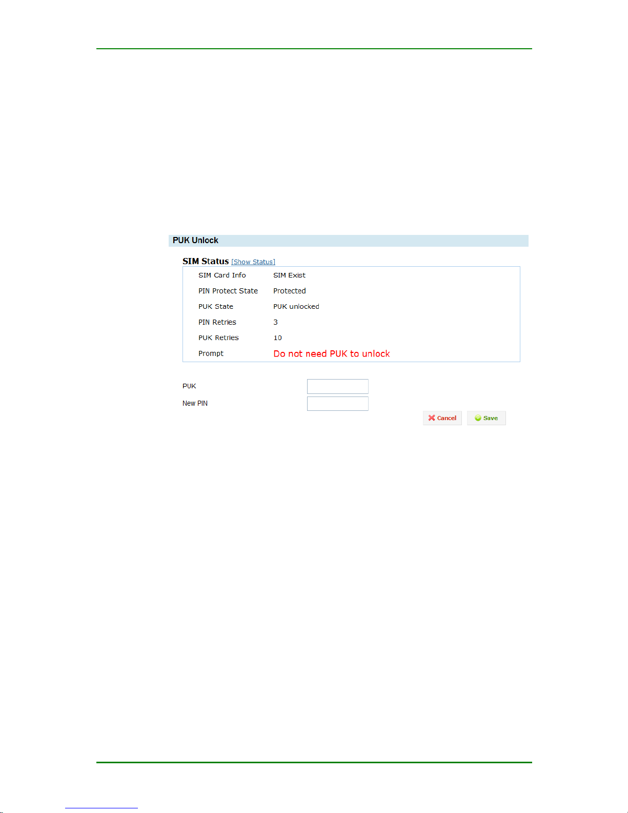
Enter Service > PIN management > PUK code unblock and the
configuration interface is as follows:
PUK code unblocking configuration interface
Page 54
MP1800-10 3G Router User Manual
Maipu Confidential & Proprietary Information Page 54 of 95
Show status: Query the current status of the SIM card, including PIN
code protect status, PIN code remaining input times, and remaining input
times of PUK code.
PUK: It comprises 8 digitals.
New PIN: It comprises 4-8 digitals.
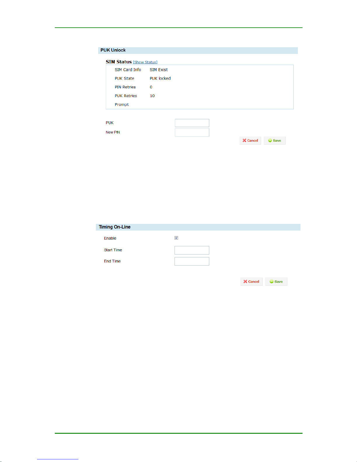
Click “Show status” and the PUK code unblocking configuration interface
is as follows:
PUK code unblocking configuration interface
After unblocking PUK code successfully and the PIN code protect is
enabled, the system automatically records the new PIN code and uses the
PIN code during dialing.
When the PUK code status in the SIM card status is “do not need PUK code
unlock”, you cannot operate the interface. You can input the PUK code to
unlock only when the PUK code status is “need PUK code unlock”. After
using the PUK code unlock successfully, the PIN code is in the protect state. The
PUK code unblock interface is as follows:
Page 55
MP1800-10 3G Router User Manual
Maipu Confidential & Proprietary Information Page 55 of 95
PUK code unlock configuration interface
Regular Online/Offline
The regular online/offline module of MP1800-10 router is used to set the
3G online time and offline time of the system so that the 3G network is
used only within the online time range, so as to save the traffic and
improve the device security. Enter Service > Regular online/offline
and the configuration interface is as follows:
Regular Online/Offline
Enable: If ticking, enable the regular online/offline function.
Start time: Set the 3G to be online at one time point. The format is hour:
minute. The range is 00:00-23:59.
End time: Set the 3G to be offline at one time point. The format is hour:
minute. The range is 00:00-23:59.
Disconnection Detection
The disconnection detection function checks whether the specified server
is available via the ICMP packet, so as to judge whether the network is
normal. When the network is abnormal, restart the device.
Page 56
MP1800-10 3G Router User Manual
Maipu Confidential & Proprietary Information Page 56 of 95
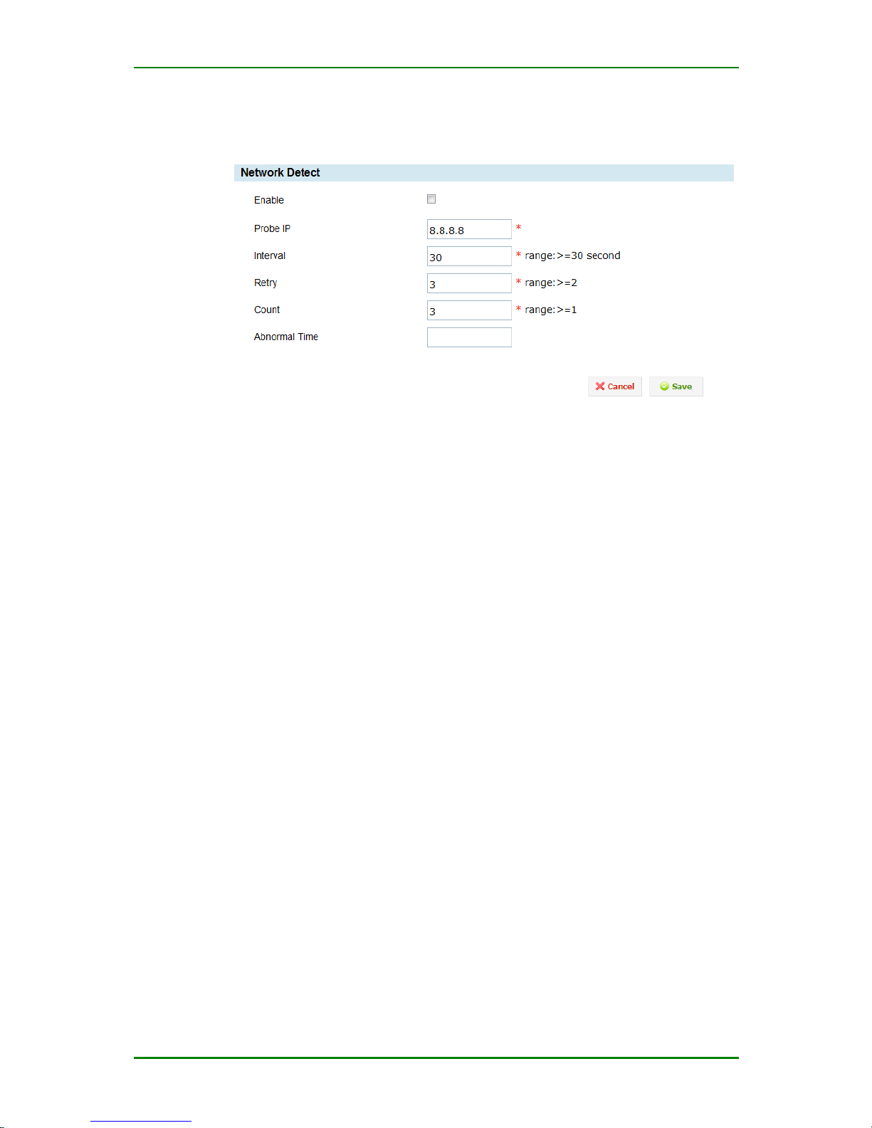
The specific configuration mode: Enter Service > Disconnection
detection, as follows:
Disconnection detection
Enable: If ticking, enable the disconnect detection function.
Probe IP: The destination address of the ICMP detect packet.
Interval: The interval of sending the ICMP packet.
Retry: When detecting for the configured times successively failed, the
device automatically restarts.
Count: The number of the ICMP packets every time
Abnormal Time: The waiting time for the device to restart because of the
SIM card arrears, wrong dial parameter configuration, and poor network
signal.
Caution
The function does not take effect when dialing on demand and the device
is forced to offline.
Multi-WAN Port Service
The multi-WAN port service mainly realizes the backup function of the WAN port.
The WAN port backup function has two work modes, that is, active mode and
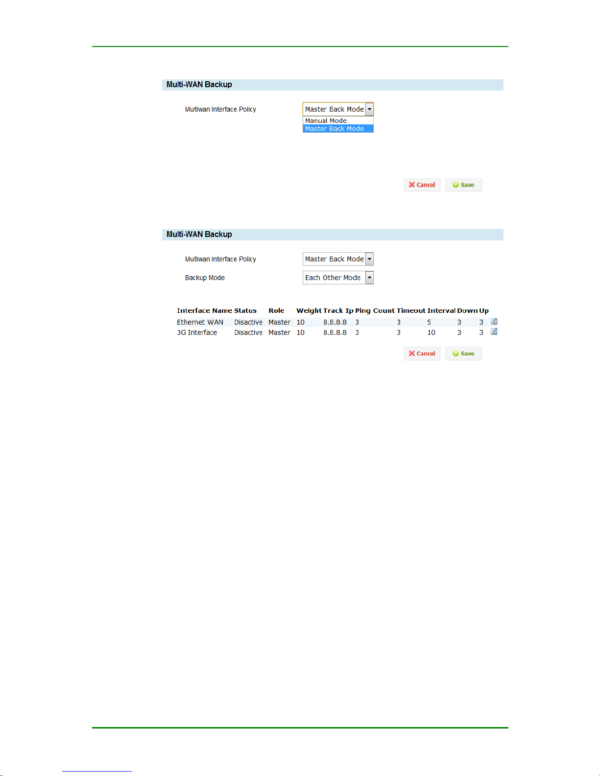
active/standby mode. Enter Service > Multi-WAN port service status
interface, as follows:
Page 57
MP1800-10 3G Router User Manual
Maipu Confidential & Proprietary Information Page 57 of 95
Multi-WAN port interface status interface 1
Multi-WAN port interface status interface 2
Multiwan Interface Policy: Select multi-WAN work policy. There are two
policies, that is, manual mode and backup mode. The manual mode means that
when using dial interface and Ethernet WAN port separately, the user needs to
configure the static route manually; the backup mode means to select one
interface as the work interface according to the status of the dial interface and
Ethernet WAN port and the other interfaces work as the backup of the work
interface.
Backup Mode: There are two work modes in the backup mode, that is, active
mode and active/standby mode. The active mode means that the first working
mode works and does not switch to the other interface unless being disconnected.
The active/standby mode means that as long as the active interface is normal,
we use the active interface to work.
Interface configuration information: Click the edit button of the interface
configuration information and you can configure it. The configuration interface is
as follows:
Page 58
MP1800-10 3G Router User Manual
Maipu Confidential & Proprietary Information Page 58 of 95
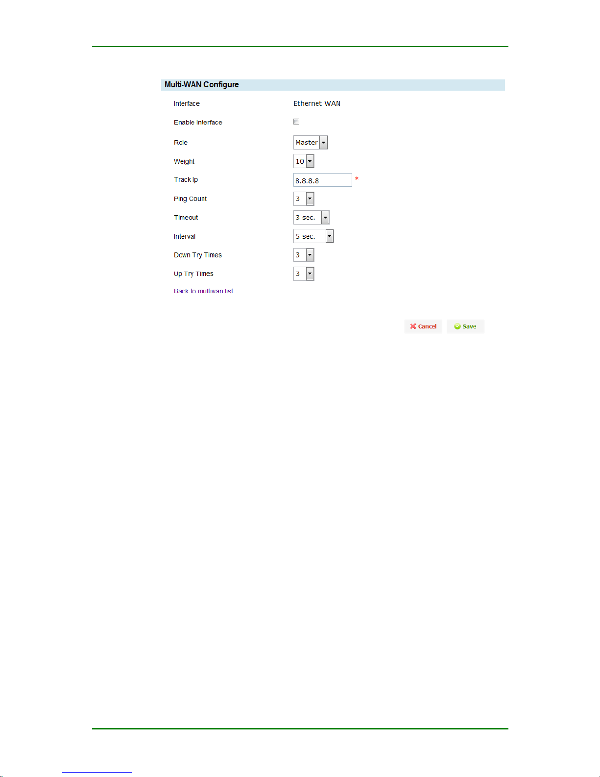
Multi-WAN service interface configuration interface
Interface: The name of the interface
Enable interface: After ticking, enable the multi-WAN port service on the
interface
Role: The role of the interface in the multi-WAN port backup function. The
metric value in the load balance.
Weight: The weight of the route in the load balance.
Track IP: Detect whether the link is the fluent IP address. It is suggested
to fill in one fixed address in the network.
Ping Count: The times of ping keepalive address in the link detection.
Timeout: The timeout of the ping keepalive address in the link detection.
The timeout value had better be larger than the ping count.
Interval: The interval of detecting the link.
Down Try Times: The interface becomes invalid when the link detection
reaches the invalid times.
Up Try Times: The interface becomes valid when the link detection
reaches the valid times.
Page 59
MP1800-10 3G Router User Manual
Maipu Confidential & Proprietary Information Page 59 of 95
Status Firewall
The status firewall functions of MP1800-10 router include:
Basic setting
Access control
Port mapping
MAC-IP binding
Basic Setting
Basic setting is the default action used to set the current MP1800-10
router firewall, including the default processing policy of the firewall,
whether to filter Ping packets from Internet, whether to prevent DOS
attack, and whether to enable the status firewall. Enter Status firewall >
Basic setting and the setting interface is as follows:
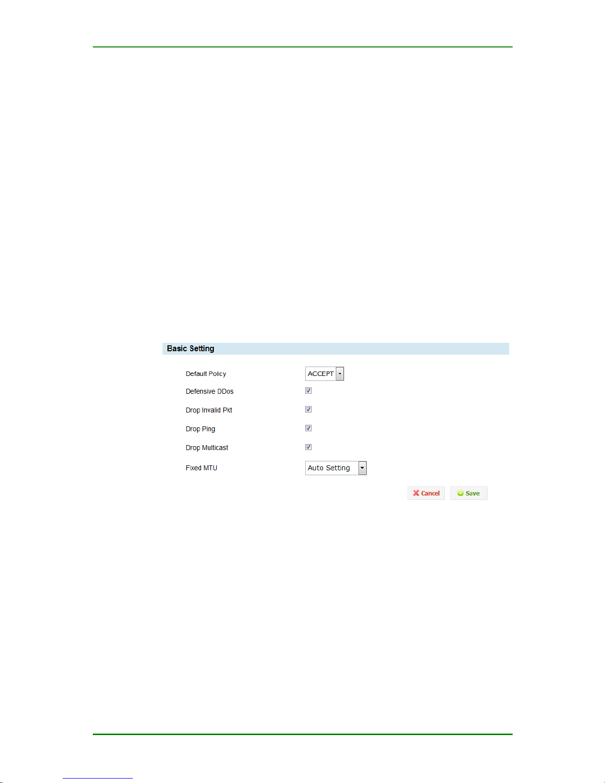
Basic setting
Default Policy: Set the default action of the firewall. If the packets
forwarded via the firewall do not match any valid rule, execute the default
processing action.
Filter Ping packets from Internet: If ticking the item, filter the external
Ping packets.
TCP MSS setting mode: You can select the manual setting and auto
setting modes.
TCP MSS: Set the TCP MSS value manually. The value range is 500-1460.
Prevent Dos attack: If ticking the item, the system can prevent the
external Dos attacks.
Page 60
MP1800-10 3G Router User Manual
Maipu Confidential & Proprietary Information Page 60 of 95
Error packet detect: If selecting the item, the system can filter the
invalid packets.
Access Control
The firewall security control is realized via the added security rule. To
realize one IP filter control, you should add the corresponding control rule
to the IP filter rule base of MP1800-10 router so that you can use MP180010 to perform the security control protect. Enter Status Firewall >
Access control and the configuration interface is as follows:
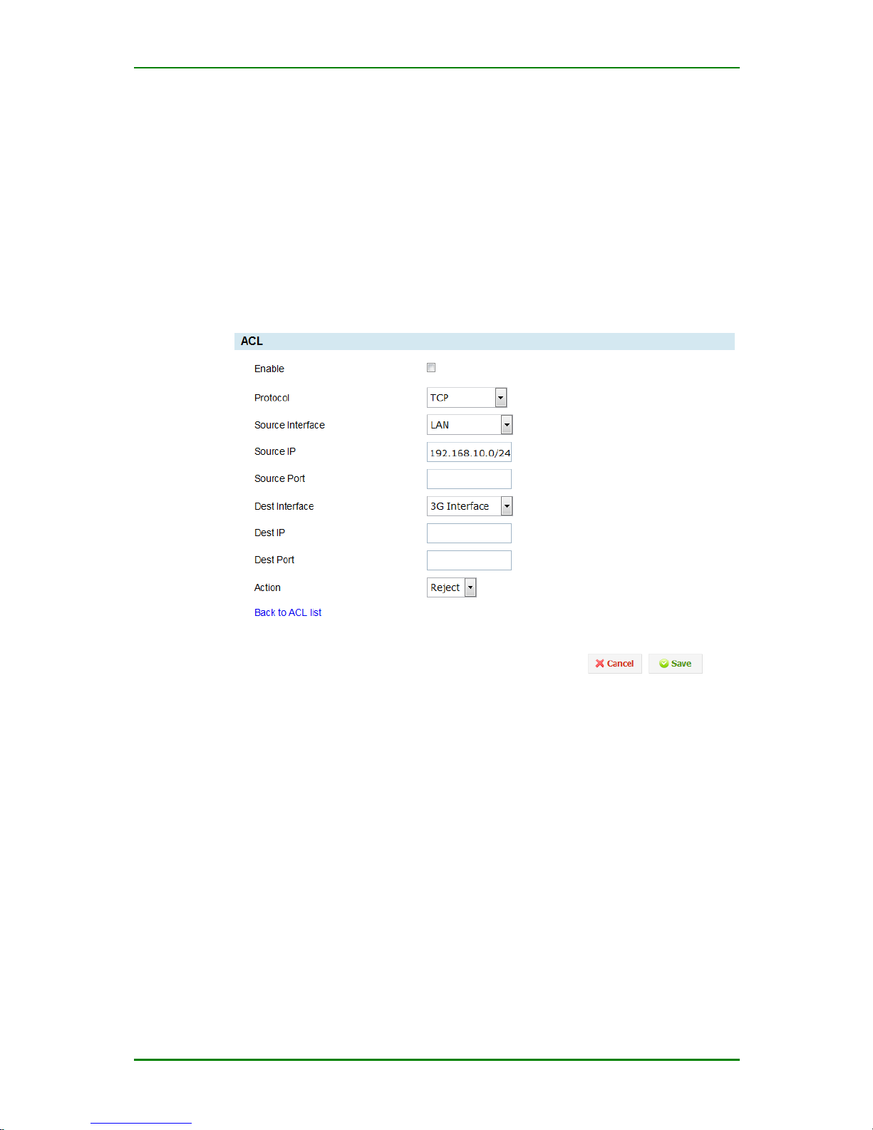
Access control
Enable: If ticking the item, enable the rule.
Protocol: It can be TCP protocol, UDP protocol, ICMP protocol or specify
the TCP and UDP protocol at the same time.
Source IP: It is the IP or segment of the intranet PC, such as
192.168.10.0/24.
Source Port: It can be a section, such as 22-8888. If you are not sure
about the source port, you’d better not fill.
Dest IP: It can be a section, same as the source IP address.
Dest port: It can be a section, same as the source port.
Action: Specify the processing mode of the rule for packets
(accept/refuse/drop).
Page 61
MP1800-10 3G Router User Manual
Maipu Confidential & Proprietary Information Page 61 of 95
Click and you can delete the corresponding rule.
Note
If you want to prohibit LAN from accessing most of Internet services, you
can add settings as follows:
Step 1: Prohibit the access for all Internet services;
Step 2: Enable the exceptional services.
All rules of the firewall comply with the principle “Configure later and
match earlier”.
Port Mapping
With the NAT function of MP1800-10 router, you can perform the one-toone mapping between Internet public IP address and internal private IP
address. Enter Status firewall > Port mapping and you can see the
following configuration interface:
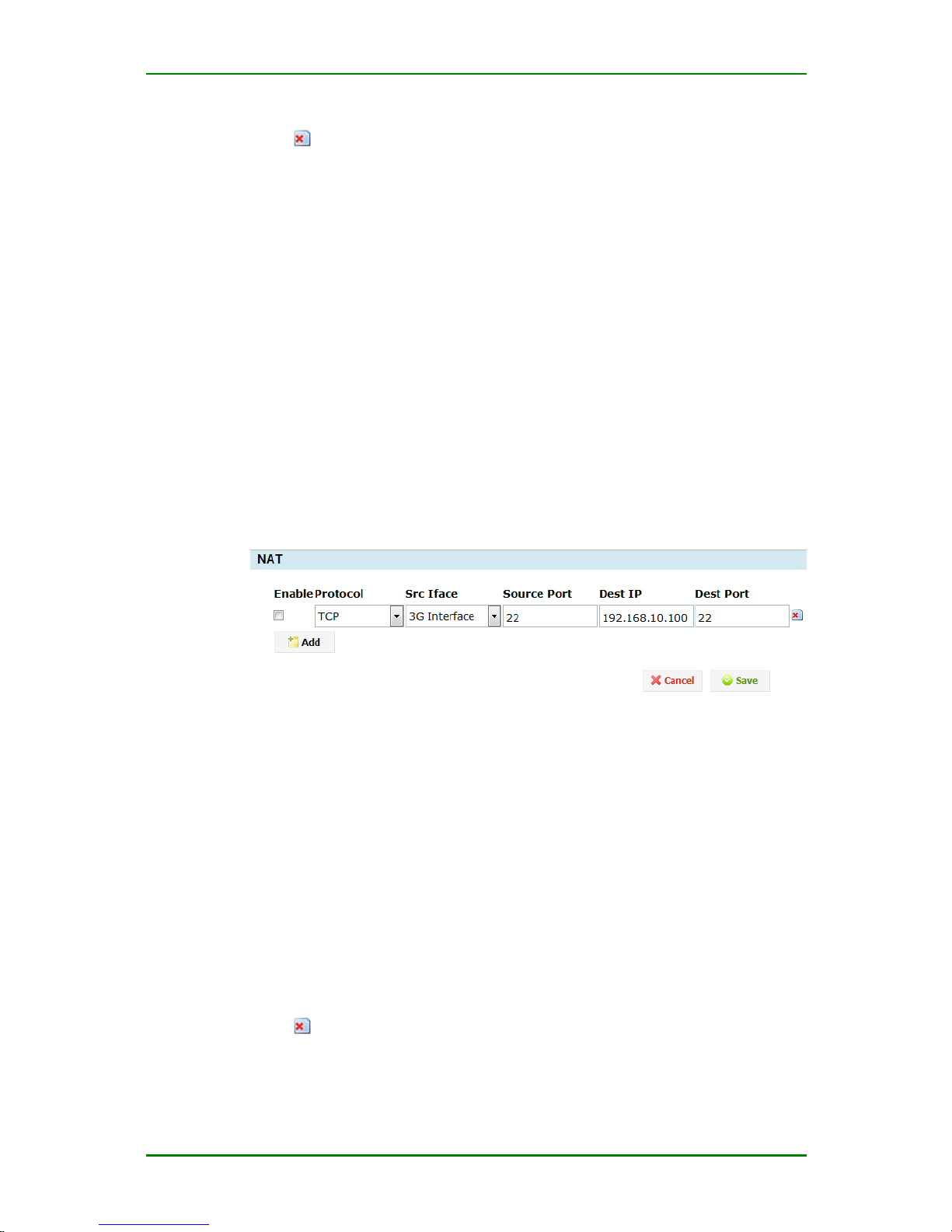
Port mapping
Enable: If ticking the item, it is enabled.
Protocol: It can be TCP, UDP or specify the two at the same time.
Source interface: The interface for receiving packets
Source port: It is one specified integer. It refers to the source port of the
desired mapping.
Dest IP: It is the IP address of Internet one PC. It refers to the IP address
of the destination host to be mapped.
Dest Port: One port of the destination IP. The number of the destination
port to be mapped.
Click and you can delete the corresponding port mapping.
Caution
Page 62
MP1800-10 3G Router User Manual
Maipu Confidential & Proprietary Information Page 62 of 95
After adding the port mapping information, you should click Save to make
the device valid. Before saving, do not switch to the other interface.
MAC-IP Binding
The MAC-IP binding function is used to limit the host with the specified IP
address in LAN to filter the packets according to the mode of matching IP
and MAC at the same time. The optional filter modes are accept, refuse, or
drop.
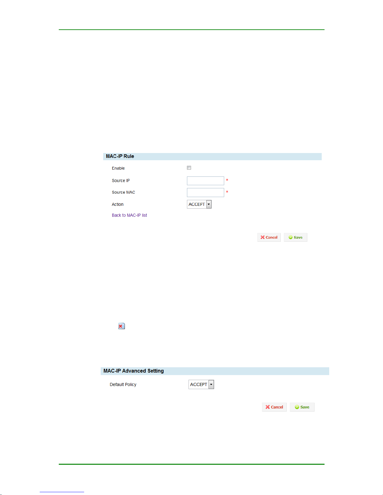
Rule setting
MAC-IP binding rule setting
Source IP: The actual valid IP address of one host in the LAN, such as
192.168.10.11.
Source MAC: The MAC address of the LAN computer, such as MAC:
00:50:56:C0:00:08.
Action: Specify the processing action. It can be accept, refuse, or drop.
Click and you can delete the MAC-IP binding.
Advanced setting
Advanced setting of MAC-IP binding
Page 63
MP1800-10 3G Router User Manual
Maipu Confidential & Proprietary Information Page 63 of 95
Default Policy: The default processing mode of the firewall for the IP
address not on the rule setting interface.
QOS
The QoS of MP1800-10 router includes bandwidth management.
Bandwidth Management
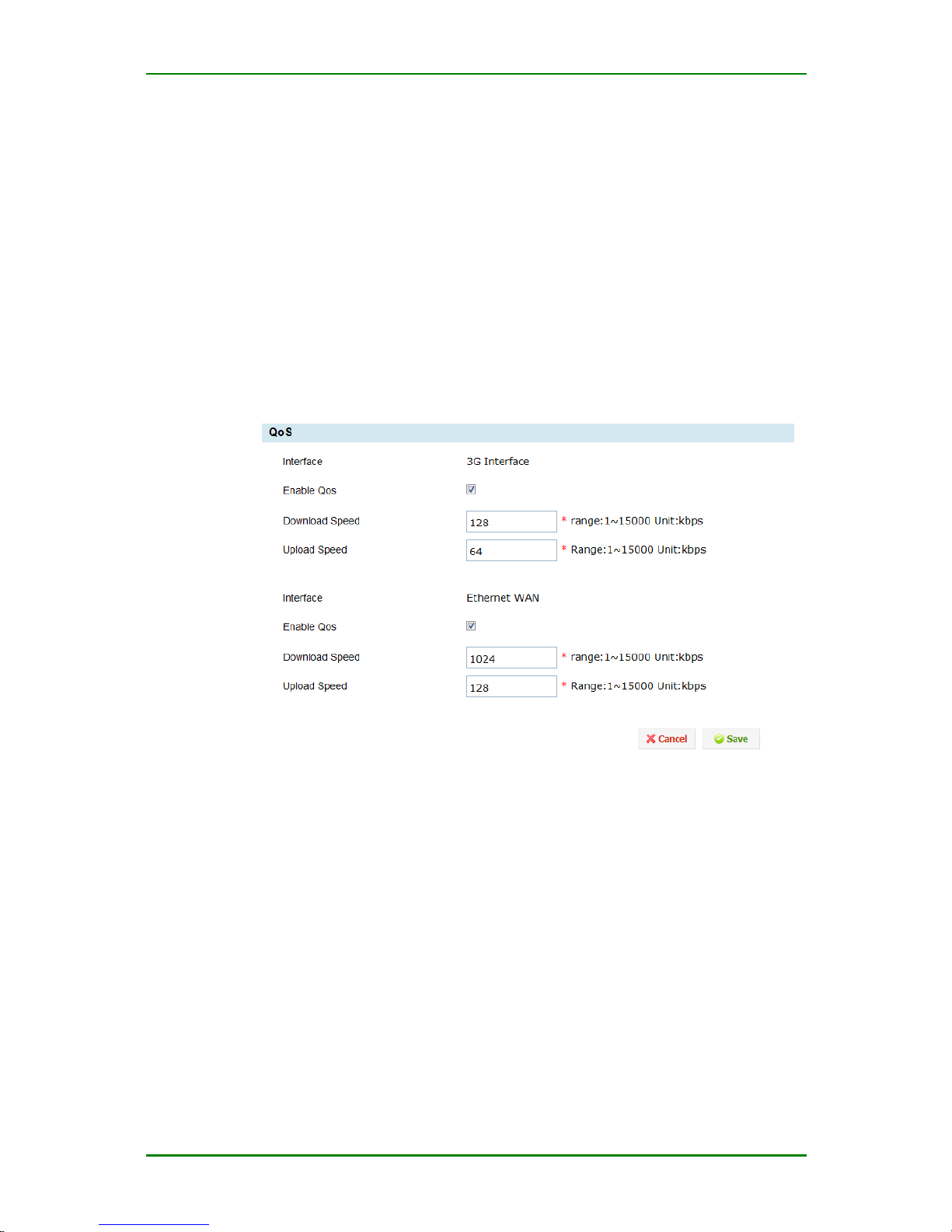
Enter QoS > Bandwidth Management, tick Enable and you can set the
downloading speed and uploading speed, as follows:
Bandwidth management
Interface: The name of the network interface.
Enable QoS: You can set as enabled state or disabled state. After setting
as enabled, you can specify the downloading and uploading rate.
Download speed: Specify the downloading speed (the unit is kbps).
Upload speed: Specify the uploading speed (kbps).
Page 64
MP1800-10 3G Router User Manual
Maipu Confidential & Proprietary Information Page 64 of 95
VPN Configuration
VPN (Virtual Private Network) is one security LAN based on Internet.
Currently, MP1800-10 router supports IPSec and GRE, providing the
flexible, economical, and valid scheme for the enterprise network security.
The “VPN configuration” function of MP1800-10 router includes:
IPSEC
GRE
Certificate management
IPSec
IPSec (IP Secure Protocol) is one of VPN technologies. The protocol not
only refers to the data encryption and decryption technology, but also
refers to the data transmission and validation technology. It is often used
for the end-to-end network security transmission.
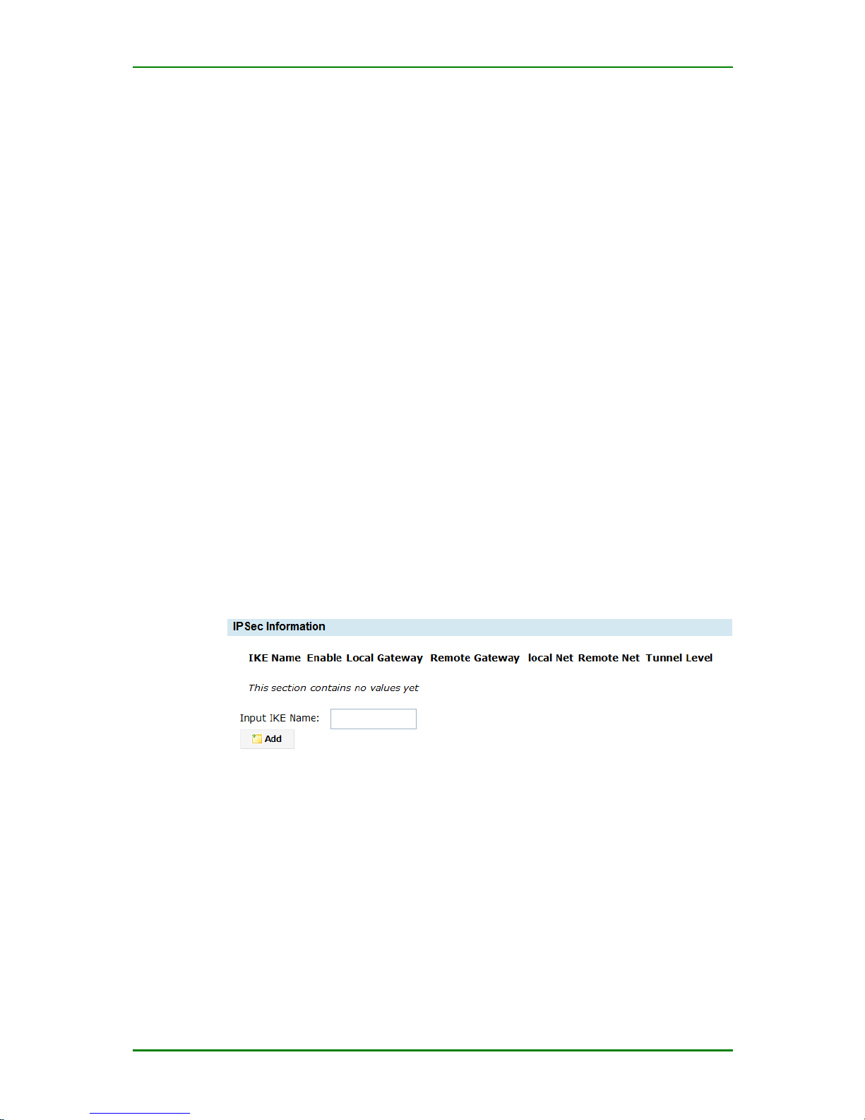
IPSEC tunnel configuration
Enter VPN > IPSec > Configure Tunnel and you can enter the IPSEC
configuration interface, as follows:
IPSec tunnel management
Input IKE Name: The phase-1 ID, setting one name for the IPSec tunnel.
Caution
1. When modifying the VPN tunnel configuration, the phase-1 ID
cannot be modified.
2. By default, the IPSec service of MP1800-10 router is disabled.
To make all created rules take effect, you should enable the
service when enabling one rule.
Page 65
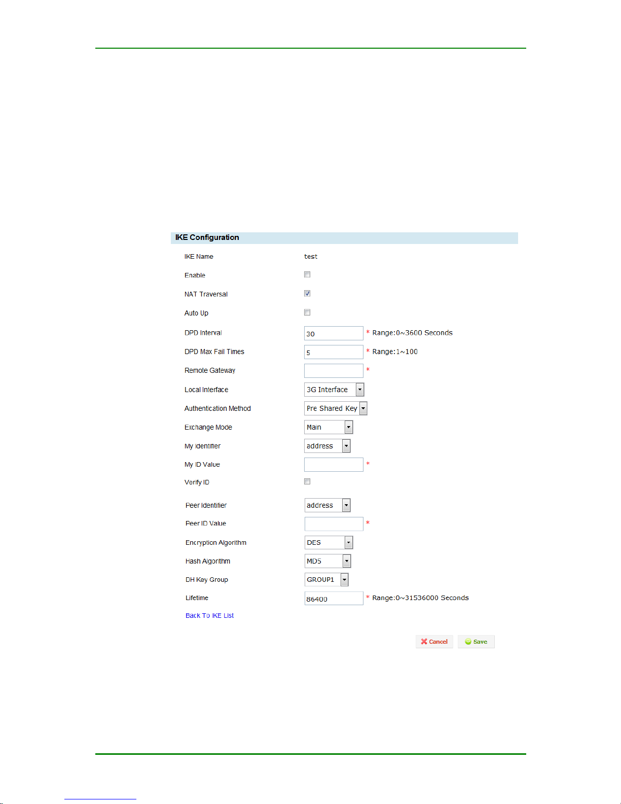
MP1800-10 3G Router User Manual
Maipu Confidential & Proprietary Information Page 65 of 95
3. The IPSec tunnel configuration includes two phases: phase 1
and phase 2.
1. Add rule
After inputting the tunnel name on the interface as shown in Figure 4-50,
click Add to enter the interface for configuring the IPSec tunnel
parameters, as follows:
Basic configuration:
IPSec phase-1 basic configuration
Phase-1 configuration:
Page 66

MP1800-10 3G Router User Manual
Maipu Confidential & Proprietary Information Page 66 of 95
Enable: The switch of enabling the IPSec tunnel. By default, it is disabled.
If ticking, it is enabled.
NAT Traversal: To prevent the NAT gateway from affecting the IPSec
tunnel, it is recommended to enable the NAT traverse (the tunnel data can
traverse the NAT gateway).
Auto Up: After completing and saving the tunnel configuration, the
system automatically negotiates the tunnel. If ticking, it is enabled.
DPD interval: The interval of the security tunnel detecting the peer
status (description: With the DPD interval, IPSEC sends one DPD detection
packet to judge whether the tunnel peer exists. If the peer does not
respond, IPSEC initiates re-negotiation).
DPD Max Fail Times: Set the maximum re-transmission times of the
security tunnel peer status detection.
Remote gateway: The remote gateway address (usually, it is the remote
public IP address).
Local Interface: Select the interface at the local used to set up the
tunnel with the remote.
Authentication Method: You can select the pre-share key or digital
certificate. Usually, we select the pre-share key.
Center certificate name: Select the certificate of the authentication
center (CA certificate). The certificate requires uploading the
corresponding certificate in the certificate uploading configuration item.
(The item depends on the authentication mode as digital certificate and
the local ID type as ASD1DN.)
Certificate content: Select the digital certificate. The certificate requires
uploading the corresponding certificate in the certificate uploading
configuration item. (The item depends on the authentication mode as
digital certificate and the local ID type as ASD1DN.)
Certificate private key: Select the corresponding private key of the
digital certificate. The certificate requires uploading the corresponding
certificate in the certificate uploading configuration item or being got from
the certificate application. (The item depends on the authentication mode
as digital certificate and the local ID type as ASD1DN.)
Exchange mode: You can select the master mode and positive mode.
Usually, we select the master mode.
My Identifier: You can select address, FQDN, USER_FQDN, and ASD1DN.
My ID value: You can input the corresponding tag according to the
selected local ID. The inputting method depends on the local ID type.
When selecting IP address, input the local IP address; when selecting
FQDN or USER_FQDN, you can fill in the character string; when selecting
ASD1DN, the item does not exist. ASD1DN is used for the digital
certificate.
Page 67
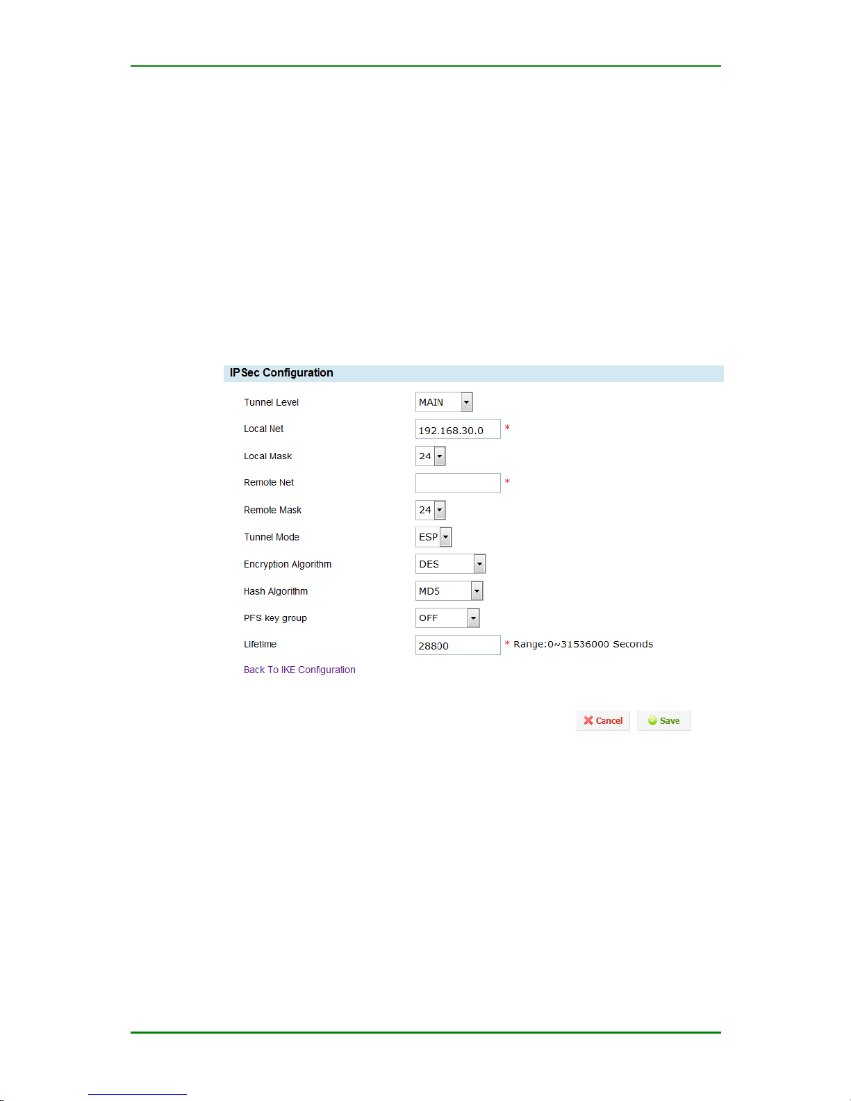
MP1800-10 3G Router User Manual
Maipu Confidential & Proprietary Information Page 67 of 95
Verify ID: If ticking the item, it is necessary to identify the peer ID.
Encryption algorithm: The encryption algorithm used by IPSec phase-1.
You can select DES, 3DES, blowfish, and aes. The default value is DES (for
RM1800-10C, RM1800-10W, RM1800-10).
Hash Algorithm: The authentication algorithm used by IPSec phase-1.
You can select MD5, SHA1, and SHA256. The default value is MD5.
DH Key Group: Select the desired key group (the key group is also the
DH algorithm).
Lifetime: IPSec phase-1 life period.
IPSec phase-2 basic configuration
Phase-2 configuration:
Local subnet
Tunnel Level: Realize the tunnel backup function. If there is no tunnel
backup, select the active tunnel.
Local Net: IPSec local protect subnet, such as 192.168.10.0;
Local Mask: IPSec local protect subnet mask, such as 255.255.255.0,
select 24;
Page 68
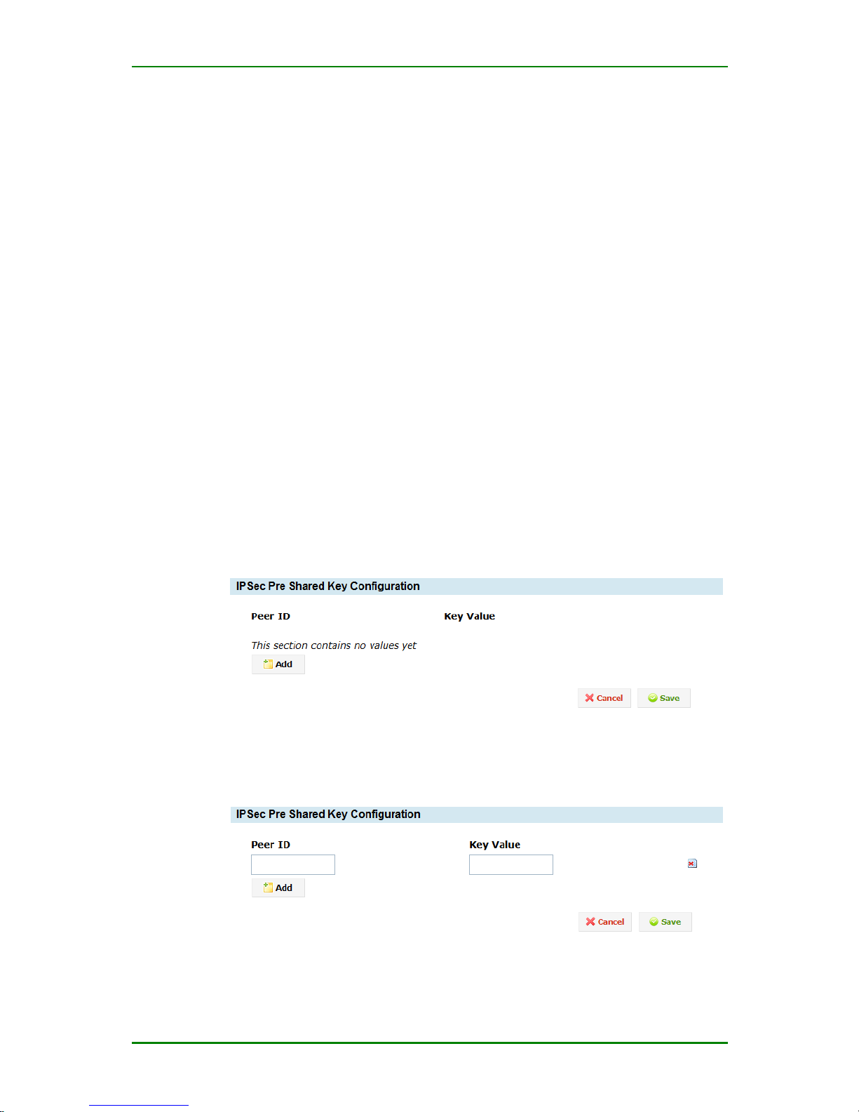
MP1800-10 3G Router User Manual
Maipu Confidential & Proprietary Information Page 68 of 95
Remote Net: IPSec remote protect subnet, such as 192.168.20.0
(network number or single host, depending on the peer IPSEC tunnel
configuration)
Remote Mask: IPSec remote protect subnet mask, such as
255.255.255.0, select 24;
Tunnel Mode: You can select ESP protocol and AH protocol. Usually, we
select ESP protocol.
Encryption Algorithm: The encryption algorithm used by IPSec phase-2.
You can select DES and 3DES, BLOWFISH, AES128, AES192, AES256,
NULL. DES (for RM1800-10C, RM1800-10W, RM1800-10).
Hash Algorithm: The authentication algorithm used by IPSec phase-2.
You can select MD5, SHA1, SHA2-256, and NULL. The default value is
MD5.
PFS key group: Perfect forward encryption (DH algorithm). You can
select off, 768bit, 1024bit, and 1536bit. The parameter needs to match
the peer.
Lifetime: IPSec phase-2 life period. After the life period ends, IPSEC
initiates the phase-2 parameter re-negotiation.
Pre-share key configuration
Pre-share key setting
After clicking Add on the above figure, enter the following interface for
configuring the pre-share key:
Pre-share key
Page 69
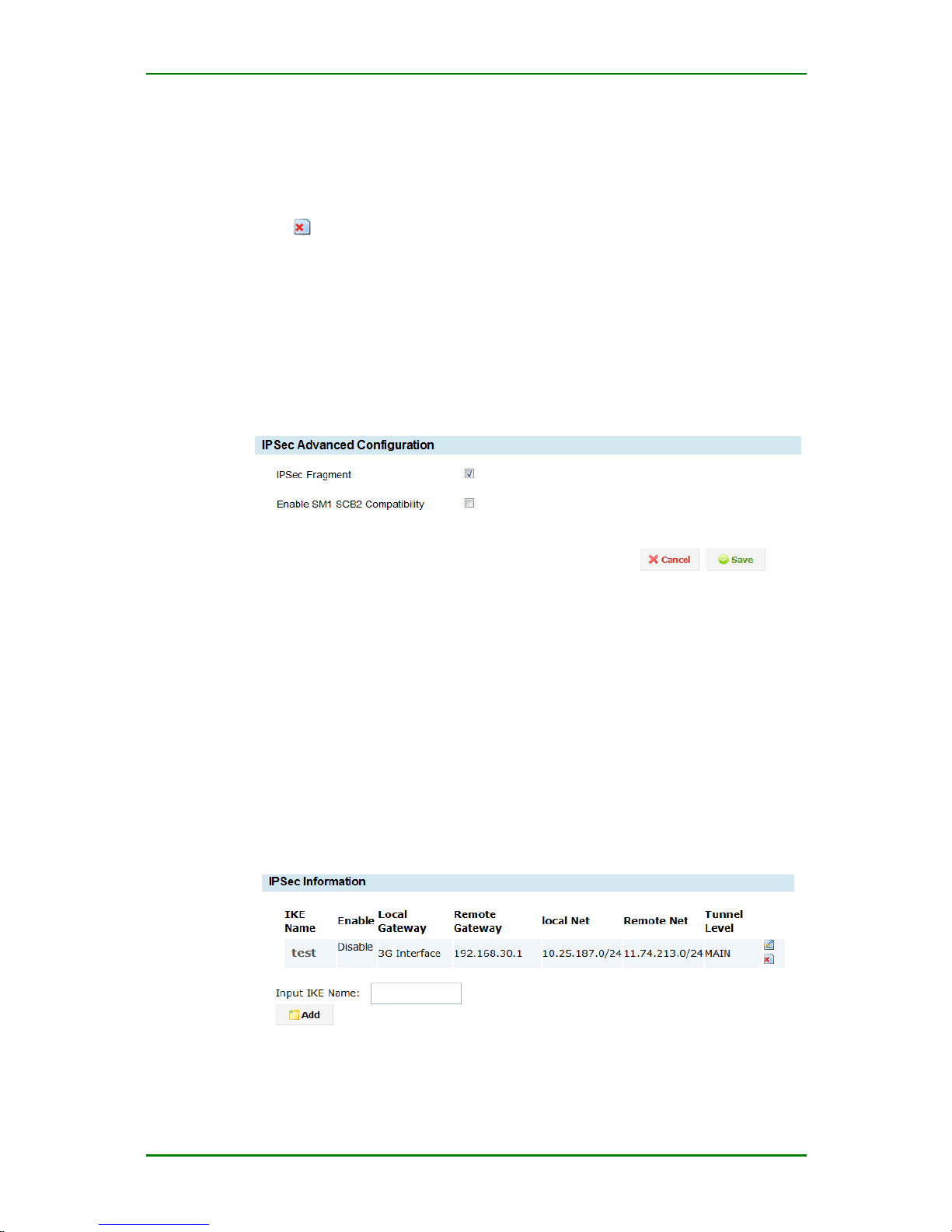
MP1800-10 3G Router User Manual
Maipu Confidential & Proprietary Information Page 69 of 95
Peer ID: The peer ID (it can be character string, IP address, domain
name).
Key Value: Used to fill in pre-share key.
Click and you can delete the corresponding key.
Caution
After adding the IPSec pre-share key configuration information, you should
click Save to make the device take effect. Before clicking Save, do not
switch to other interface.
Advanced setting
Advanced setting
IPSec Fragment: If ticking the item, enable the IPSec pre-fragment
function.
Enable SM1 SCB2 Compatibility: If ticking the item, enable SM1
compatible with SCB2 mode function.
2. Modify IPSEC tunnel configuration
When modifying one IPSec tunnel configuration, enter VPN > IPSec >
Configure tunnel, and you can enter the IPSec tunnel configuration
interface, as follows:
Modify IPSec rule
Page 70
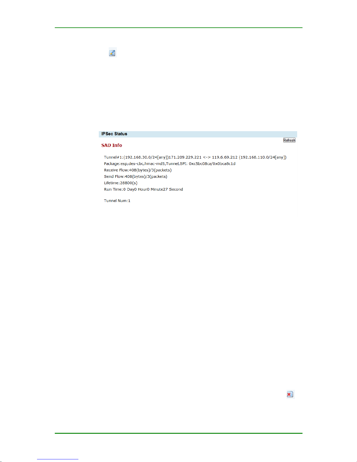
MP1800-10 3G Router User Manual
Maipu Confidential & Proprietary Information Page 70 of 95
Click in the above created tunnel list, and you can enter the interface
of configuring and editing the IPSec tunnel, as shown in Figure 4-51.
For the parameter description, refer to the above section.
3. View tunnel status
Enter Status > Tunnel status and you can view the connection status of
the current IPSec tunnel, as follows:
Tunnel connection status
SA: IPSec security association.
Tunnel: Display the gateway address at the two sides of the tunnel.
Package: Display the security protocol of the tunnel, such as esp and ah;
encryption algorithm > authentication algorithm > negotiation mode
(transport or tunnel); the security association spi (security parameter
index) of the two directions.
Receive Flow: The data traffic received from the peer via the tunnel.
Send Flow: The data traffic sent to the peer via the tunnel.
Lifetime: The maximum using time of IPSec sa.
Run Time: The time of setting up the tunnel.
Tunnel Num: The total number of the tunnels set up in the device.
4. Delete rule
When one IPSec tunnel configuration is not needed, you can click to
delete the corresponding IPSEC tunnel.
Page 71
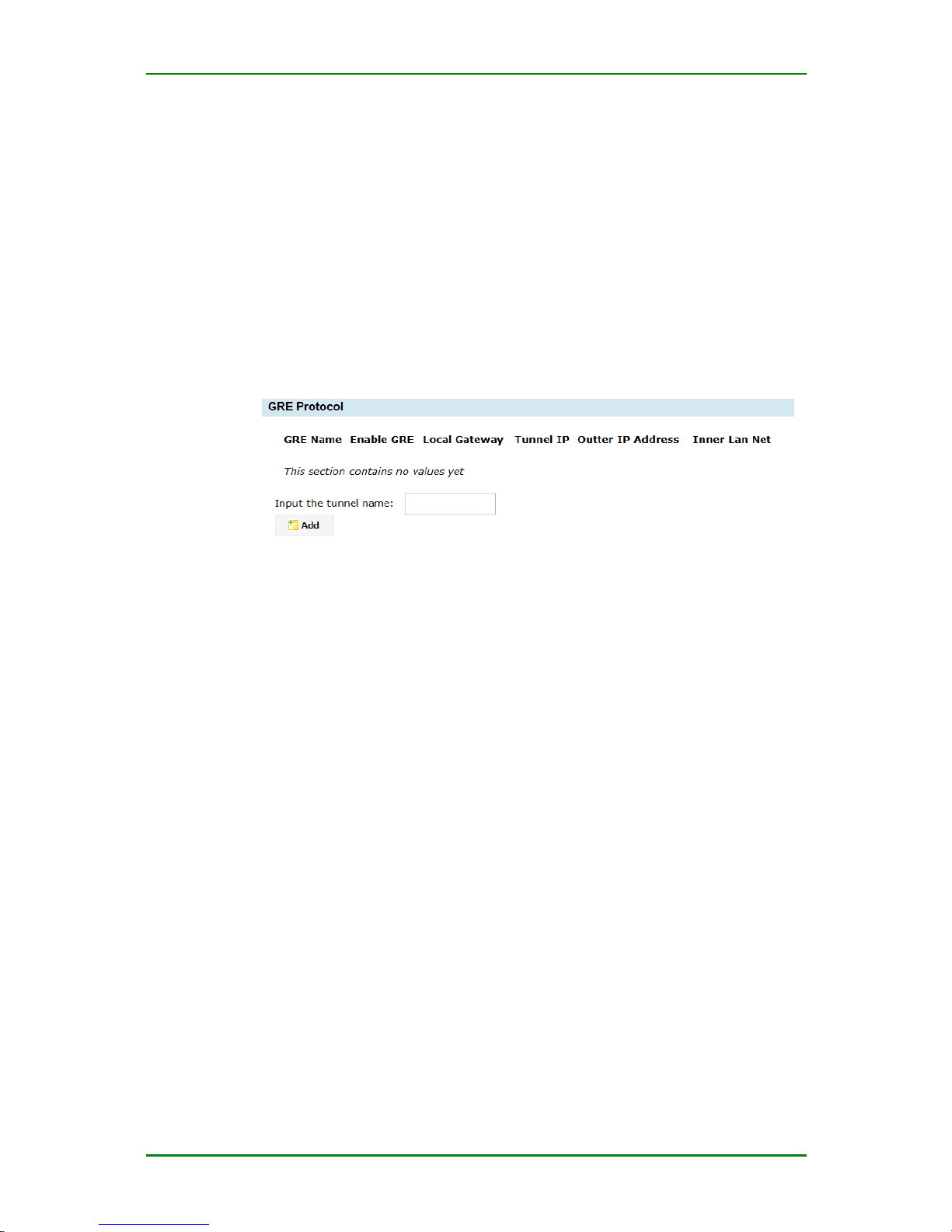
MP1800-10 3G Router User Manual
Maipu Confidential & Proprietary Information Page 71 of 95
GRE
GRE defines how to use one network protocol to encapsulate another
network protocol. The GRE protocol has two usages: Enterprise internal
protocol encapsulation and private address encapsulation. In China, nearly
all enterprise networks adopt the TCP-IP protocol, so there is no market
requirement for the enterprise internal protocol encapsulation when
setting up the tunnel in China. The unique reason why the enterprise
adopts GRE is the encapsulation for the internal address.
Enter VPN > GRE and you can enter the interface for configuring and
editing the GRE tunnel, as follows:
GRE tunnel configuration
Input the tunnel name: Used to identify one GRE tunnel.
Caution
When modifying the VPN tunnel configuration, the tunnel name cannot be
modified.
1. Add rule
Click Add on the above interface to enter the interface for configuring the
GRE tunnel parameters, as follows:
Page 72
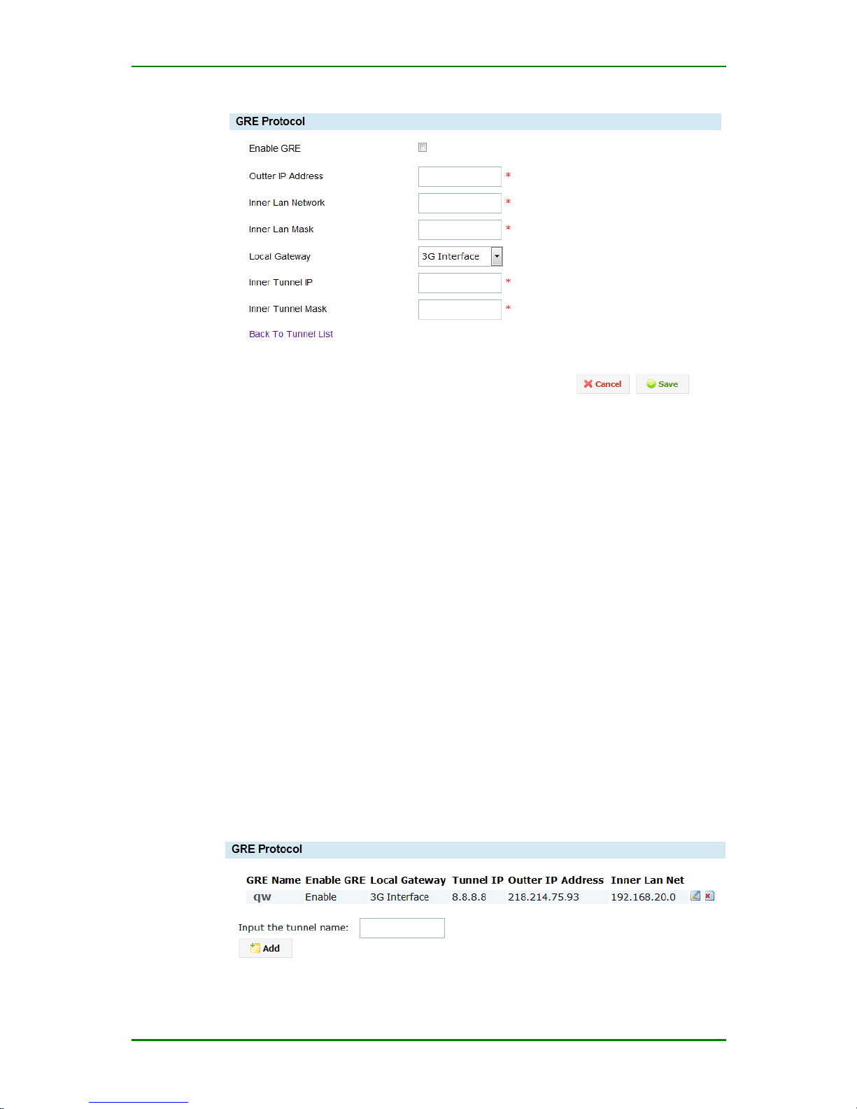
MP1800-10 3G Router User Manual
Maipu Confidential & Proprietary Information Page 72 of 95
GRE connection configuration
Enable GRE: The switch of enabling the GRE tunnel. By default, it is
disabled. If ticking the item, enable the GRE tunnel.
Outer IP Address: Set the external interface IP of the GRE tunnel peer
network. Usually, it is the public IP (Internet) address. It also can be
enterprise intranet IP.
Inner Lan Network: Set the internal interface segment of the peer
network of the GRE tunnel. It also can be one single IP address.
Inner Lan Mask: Set the subnet mask of the peer intranet of the GRE
tunnel. If it is one single host, you need to input the 32-bit mask.
Inner Tunnel IP: Set the IP address of the local GRE tunnel.
Inner Tunnel Mask: Set the network mask of the local GRE tunnel. It’d
better be at the same segment as the peer tunnel.
2. Modify GRE tunnel configuration
To modify one GRE tunnel configuration, enter VPN > GRE and you can
enter the interface for configuring and editing the GRE tunnel, as follows:
Page 73

MP1800-10 3G Router User Manual
Maipu Confidential & Proprietary Information Page 73 of 95
Edit GRE configuration
To modify one configured tunnel, click at the corresponding rule. The
interface for modifying the tunnel is as shown in Figure 4-62.
3. Delete rule
When one GRE tunnel is not needed, click and you can delete the GRE
tunnel.
Certificate Management
Introduction to related certificates of the router
The certificate is one security authentication mode. It validates whether
the peer certificate is valid to ensure the data security. Therefore, when
using the certification authentication, we need to get the valid certificate.
Currently, the router supports certificate application, direct importing of
other certificate and online certificate application.
1. Certificate application: Input the corresponding configuration item
to get the certificate application file. Submit the application file to CA
for issuing the authentication. Issuing the authentication is to make
the certificate valid.
Detailed description: The user adopts the application mode of the router
certificate to apply for one certificate request file (the suffix is csr. For the
application mode, refer to the certificate application). After the router
generates the certificate request file, it turns to the certificate uploading
management interface. The user can download to get the certificate
request file (when the router generates the certificate request rile,
generate one private key, which is automatically saved by the router to
the router inside), and then submit the certificate application file to CA for
issuing the authentication. If passing the CA authentication organization,
get one certificate file issued by CA (the suffix is crt), and then upload the
issued certificate to the “certificate application file list” of the router (note
that the uploaded location corresponds to the private key). After uploading
successfully, the user can adopt the certificate on the IPSec configuration
interface (note: the center certificate of the CA also needs to be uploaded.
Maybe the upper CA certificate of the CA also needs to be uploaded).
2. Import other certificate: get one valid certificate and private key
from the certificate authorization organization, as well as CA
certificate. After getting the certificates, the user can upload the
related certificate in “Upload Certificate” (for details, refer to the
following figure).
Page 74
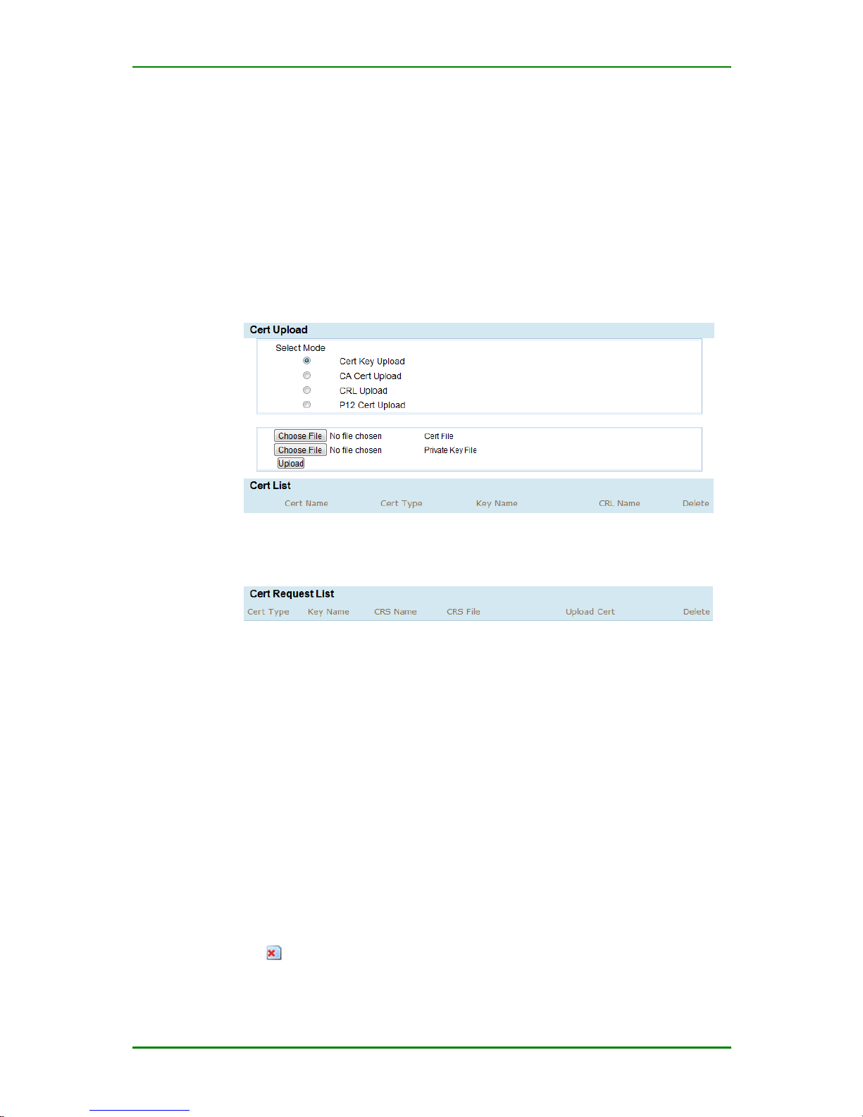
MP1800-10 3G Router User Manual
Maipu Confidential & Proprietary Information Page 74 of 95
3. Online certificate: Configure the related parameters to make the
system get the CA certificate, device certificate, and crl file from the
certificate server online. Currently, support the Windows certificate
server and Maipu CMS certificate server.
1. Certificate uploading management
To upload the certificate, click VPN > Certificate management > Certificate
uploading management and you can enter the IPSec certificate uploading
configuration interface, as follows:
Upload certificate
Cert Upload: Used to upload the certificate applied from other device.
Here, you should upload the device certificate and private key, center
certificate (CA certificate). The uploaded certificate is displayed in the
certificate list. The certificate revoke file can be used to make one
specified certificate become invalid.
Cert list: Used to display the current digital certificates uploaded to the
router.
Certificate Request List: Used to upload the certificate files. The
certificate is the csr rile generated in the “certificate application”, the
certificate issued by CA (crt) (for the application steps, refer to certificate
application).
Click and you can delete the related certificate.
Page 75
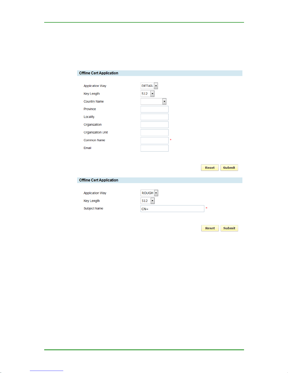
MP1800-10 3G Router User Manual
Maipu Confidential & Proprietary Information Page 75 of 95
2. Certificate application
To apply for the certificate, click VPN > Certificate management >
Certificate application and you can enter the IPSec certificate
application configuration interface, as follows (two application modes):
Certificate application
Application Way: There are two modes of filling the certificate. One is to
fill by the prompt; the other is to fill the whole subject name, applicable to
apply for the certificates with multiple same attributes (such as
CN=test,OU=mp1,OU=mp2,C=CN).
Key Length: (mandatory) the private key length.
Country Name: (optional) usually, we select CN.
Province: (optional) input the locating province.
Locality: (optional) input the name of the locating street.
Organization: (optional) input the name of the locating organization.
Page 76
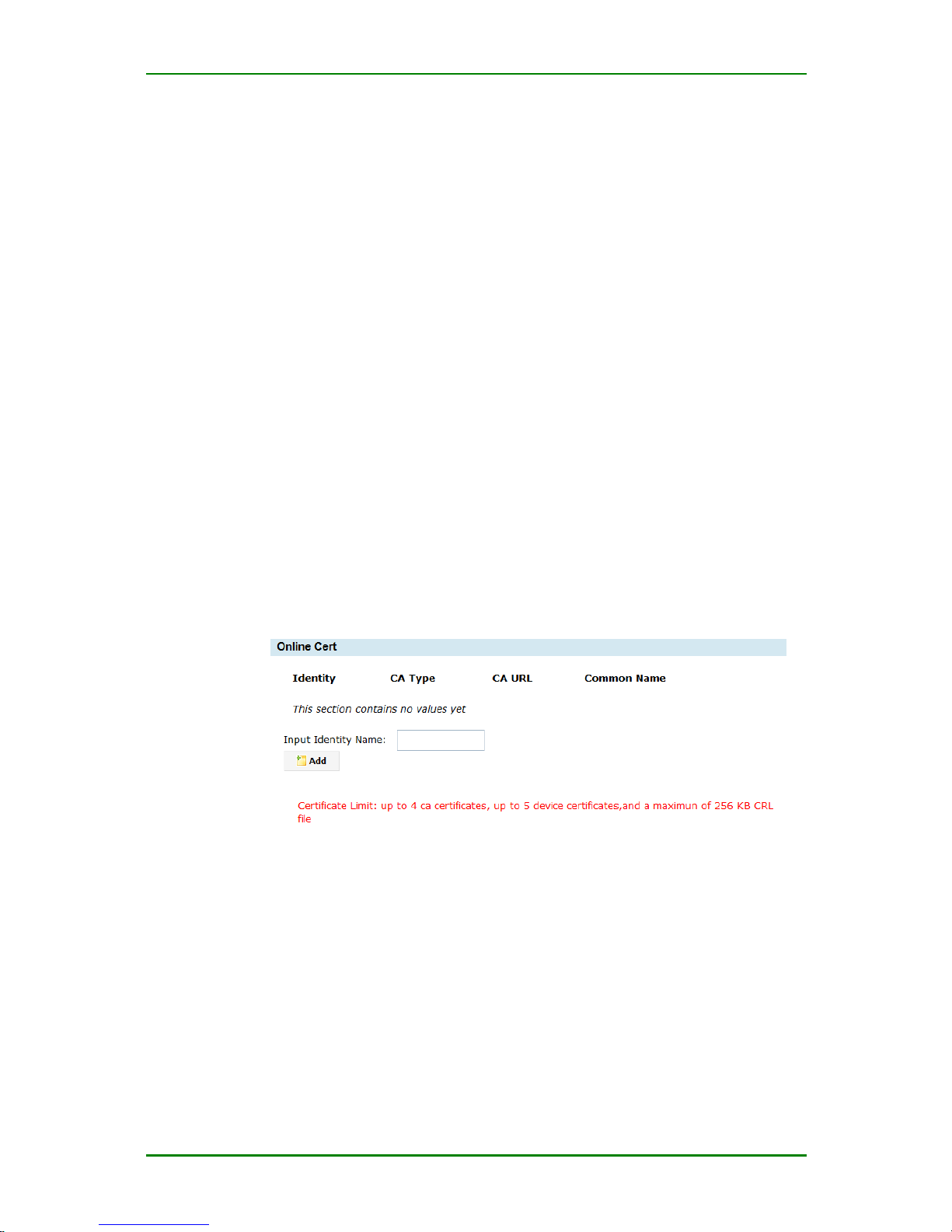
MP1800-10 3G Router User Manual
Maipu Confidential & Proprietary Information Page 76 of 95
Organization Unit: (optional) input the locating unit.
Common Name: (mandatory) You cannot input the special characters,
such as # + = > < , ; ' / )( " ; (it is unique).
Email: (optional) the email address of the company.
Click Submit and the interface turns to the certificate uploading
management interface. In the certificate application file list, you can
download and delete the certificate request file.
Prompt
When downloading the certificate request file from the certificate
application file list, it is recommended to place the mouse on the
corresponding certificate application file, right-click, and select Save as to
download.
If using the third-party download tool such as thunder, you need to tick
“download only from original address”.
3. Online certificate
To apply for the certificate, click VPN > Certificate Management >
Online certificate and you can enter the IPSec online certificate
application configuration interface, as follows:
Online certificate management ID
Input the certificate management ID (used to distinguish different online
certificate applications, such as a), and then enter the following
configuration interface (two application modes):
Page 77
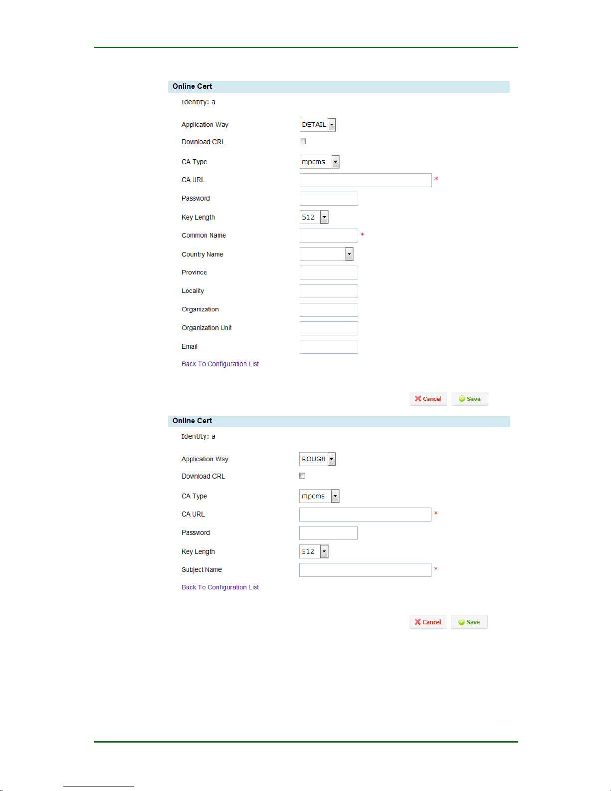
MP1800-10 3G Router User Manual
Maipu Confidential & Proprietary Information Page 77 of 95
Online certificate
CA Type: (mandatory) select the certificate server type. Currently, the
system supports Maipu CMS and Windows certificate server. Select mpcms
Page 78

MP1800-10 3G Router User Manual
Maipu Confidential & Proprietary Information Page 78 of 95
to indicate Maipu CMS server; select Windows to indicate Windows
certificate server.
Application Way: There are two modes of filling the certificate. One is to
fill by the prompt; the other is to fill the whole subject name, applicable to
apply for the certificates with multiple same attributes (such as
CN=test,OU=mp1,OU=mp2,C=CN).
Download CRL: Whether to download the certificate cancel file. By
default, it is not ticked, that is, not download.
CA URL: (optional) the url path of the server, such as Windows certificate
server http://192.168.10.1/certsrv, CMS certificate server
http://192.168.10.1.
Password: (optional) the request password when applying for the
certificate. The maximum length is 30 bits.
Common Name (CN): (mandatory) you cannot input the special
characters, such as # + = > < , " ;
County Name (C): (optional) you can select CN/HK, or do not input.
Province: (optional) input the locating province.
Locality: (optional) input the name of the locating street.
Organization: (optional) input the name of the locating organization.
Organization Unit: (optional) input the locating unit.
Email: (optional) the email address of the company.
Click Save and the system executes the online certificate application at
once. If the configuration is correct, you can get the applied center
certificate, device certificate, private key, and crl file within several
seconds. On the “Certificate uploading management” interface, you can
see the applied certificate files.
Status
With the “Status” menu, you can view the current configuration and
running status of MP1800-10 router, including:
System logs
System information
IPSec tunnel status
Page 79
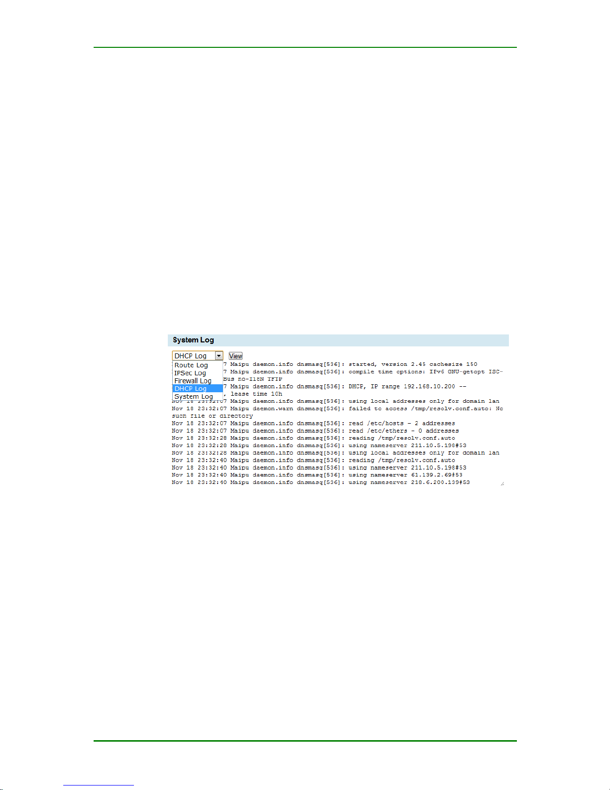
MP1800-10 3G Router User Manual
Maipu Confidential & Proprietary Information Page 79 of 95
Dialer interface status
WAN status
LAN status
Route information
DHCP information
Connection information
Restart information
System Logs
“System logs” mainly displays the log information of MP1800-10 router.
Click Status > System logs and you can see the following interface:
System logs
Prompt
The system logs include route, IPSEC, firewall, DHCP, and system. The
user can select from the drop-down list to view.
System Information
The system information mainly displays the hardware and software version
information of MP1800-10 router so that you can select the corresponding
upgrade file according to the version information when you update the
system in the future.
Page 80
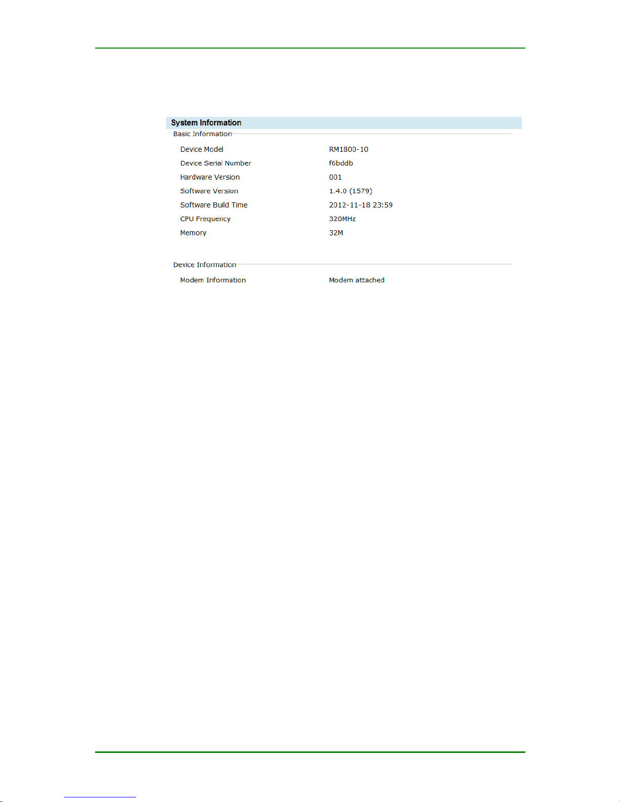
MP1800-10 3G Router User Manual
Maipu Confidential & Proprietary Information Page 80 of 95
Click Status > System information and you can see the following
interface:
System information
Device Model: MP1800-10 product model information, such as RM180010C.
Device Serial Number: The device factory serial number information.
Hardware version: The current hardware version information.
Software version: The current operation system, application software
version information.
CPU frequency: The main frequency information of MP1800-10 device.
Memory: The memory information of MP1800-10 device.
SM1 Information: The current SM1 card connection information. If the
device does not support the module, do not display.
Modem Information: The current modem connection information.
SIM Information: The current SIM connection information.
IPSec Tunnel Status
The tunnel status displays the IPSec tunnel information, displaying the
tunnel SA information.
Click Status > Tunnel status and you can see the following interface:
Page 81
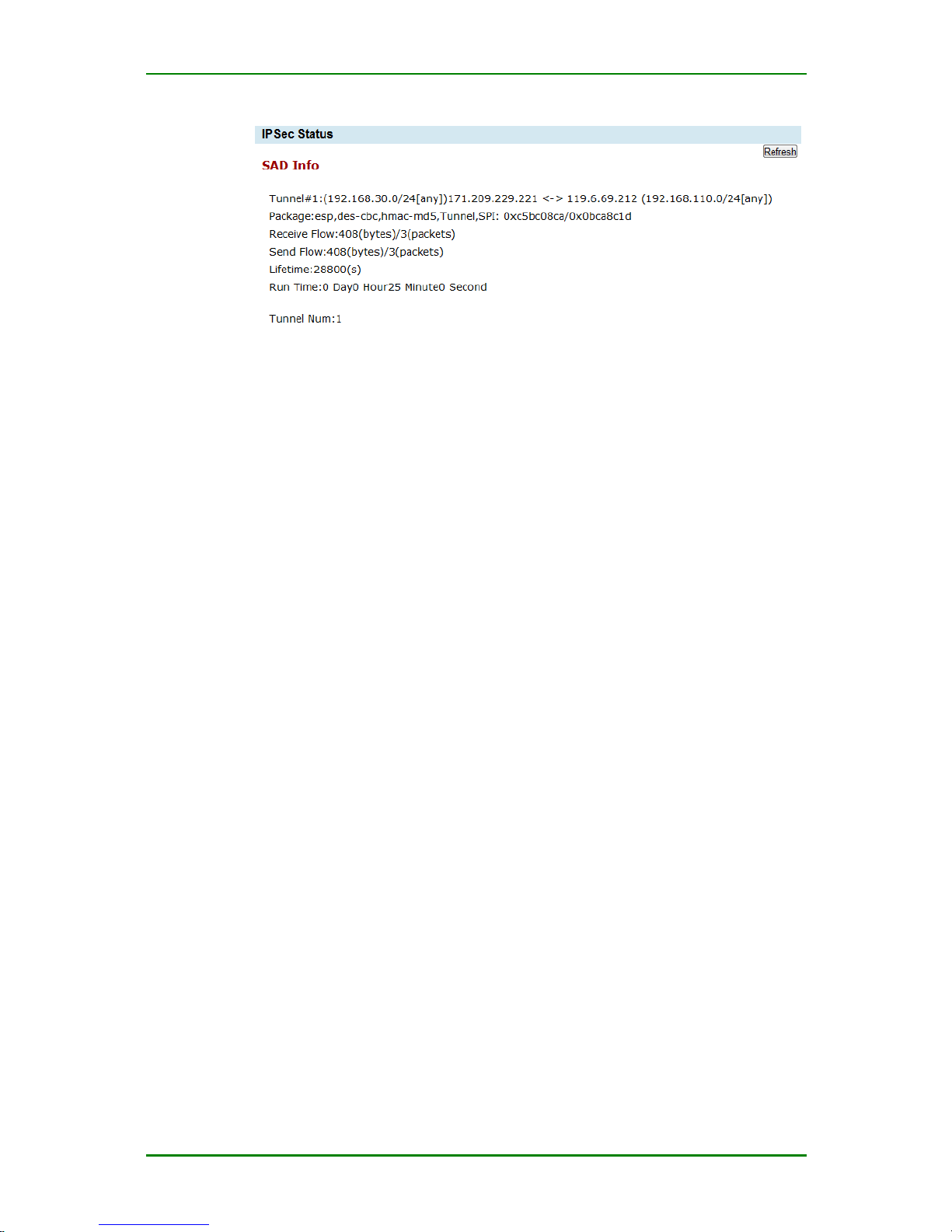
MP1800-10 3G Router User Manual
Maipu Confidential & Proprietary Information Page 81 of 95
Tunnel status
SA: IPSec security association.
Tunnel: Display the gateway addresses at the two sides of the tunnel.
Package: Display the security protocol of the tunnel, such as esp and ah;
encryption algorithm-authentication algorithm-negotiation mode
(Transport or Tunnel); the spi of the security association at the two
directions.
Receive Flow: The data traffic received from the peer via the tunnel.
Send Flow: The data traffic sent to the peer via the tunnel.
Lifetime: The maximum using time of IPSec SA.
Run Time: The time of setting up the tunnel.
Tunnel Num: The total number of the tunnels set up in the device.
Dialer Interface Status
The dialer interface status interface displays the dialer interface status,
dialer interface traffic information, and mobile network device information.
The dialer interface status displays the used wireless network module
connection information, network connection information, and whether SIM
card is in place of MP1800-10 router. With the information, you can get to
know the wireless network connection status of the current device, as
follows:
Page 82
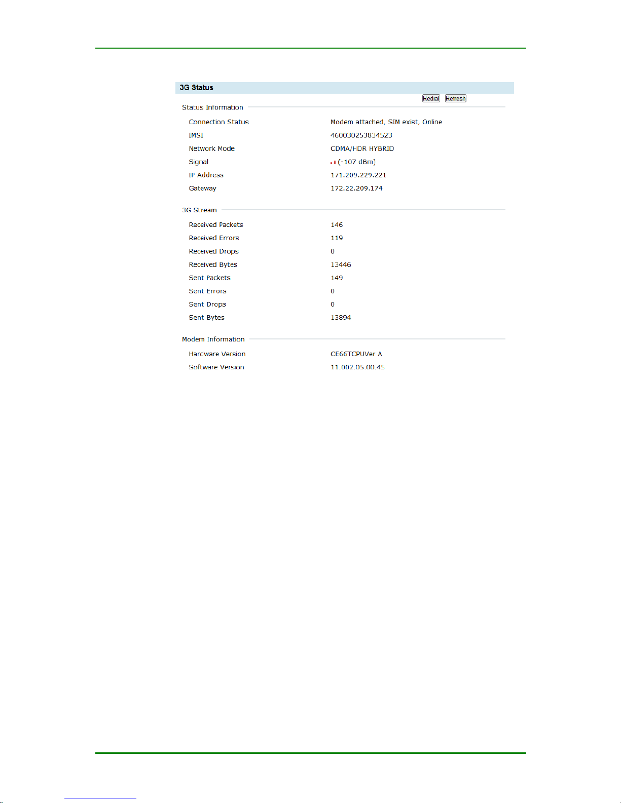
MP1800-10 3G Router User Manual
Maipu Confidential & Proprietary Information Page 82 of 95
Dialer interface status
After enabling the standby account, the dial interface status interface is as
follows:
Page 83
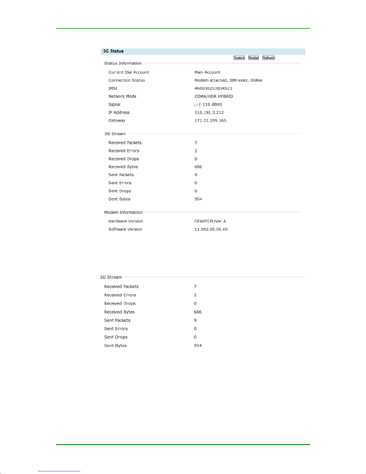
MP1800-10 3G Router User Manual
Maipu Confidential & Proprietary Information Page 83 of 95
Dial interface status
The dialer interface traffic information displays the wireless network
interface traffic information of the current device, as follows:
Dialer interface traffic information
The mobile network device information displays the wireless network
device information of the current device, as follows:
Page 84
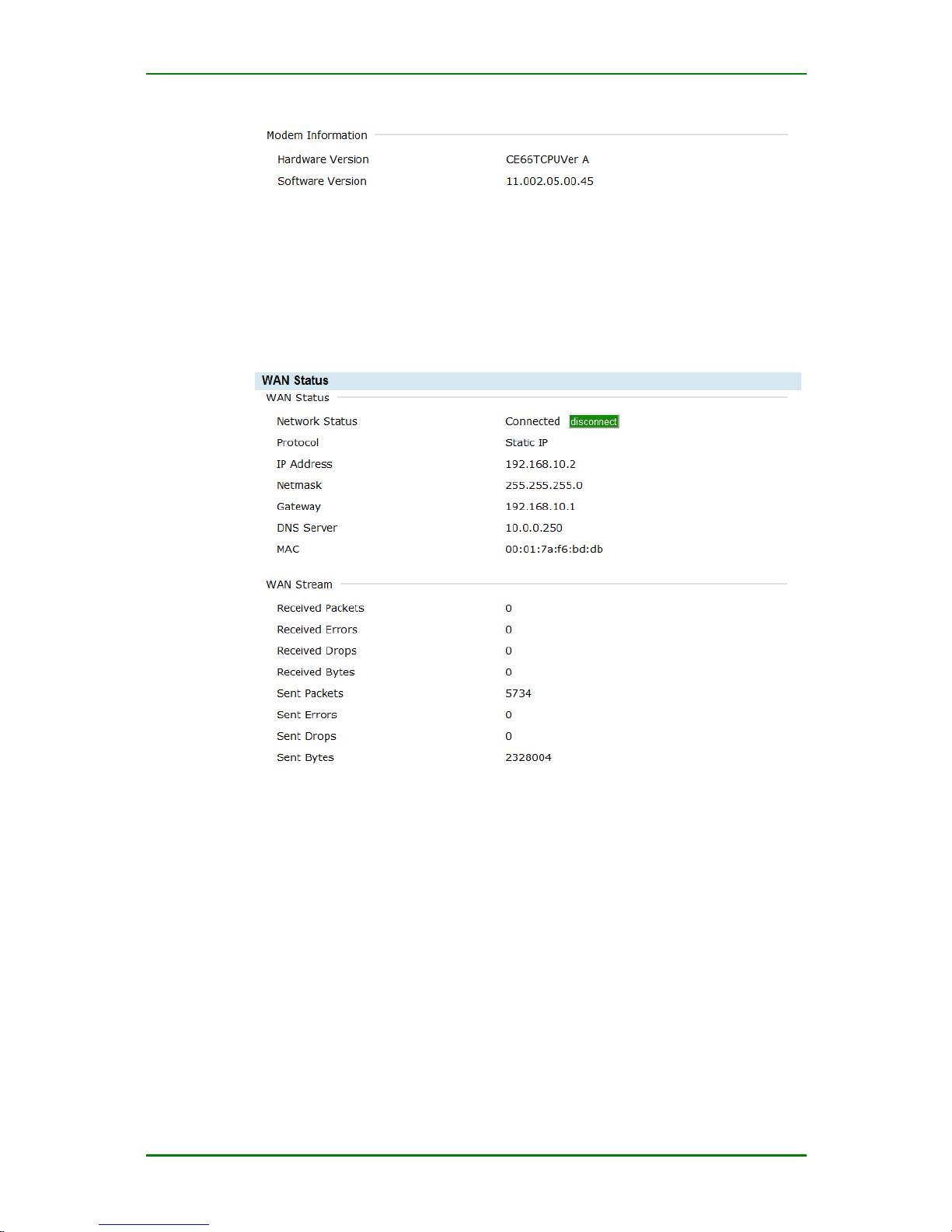
MP1800-10 3G Router User Manual
Maipu Confidential & Proprietary Information Page 84 of 95
Mobile network device information
WAN Status
The WAN status displays the current WAN interface connection mode, connection
status and the receiving and forwarding traffic of the WAN interface. Enter
Status > WAN status and you can see the following interface:
WAN status
Network Status: Display the current connection status of the WAN port
Protocol: Display the protocol used by the WAN interface
IP address: Display the IP address of the WAN port
Netmask: Display the subnet mask of the WAN port
Gateway: Display the gateway address of the WAN port
DNS Server: Display the DNS server address of the WAN port
MAC: Display the physical address of the WAN port. The address is fixed
and unique.
Page 85
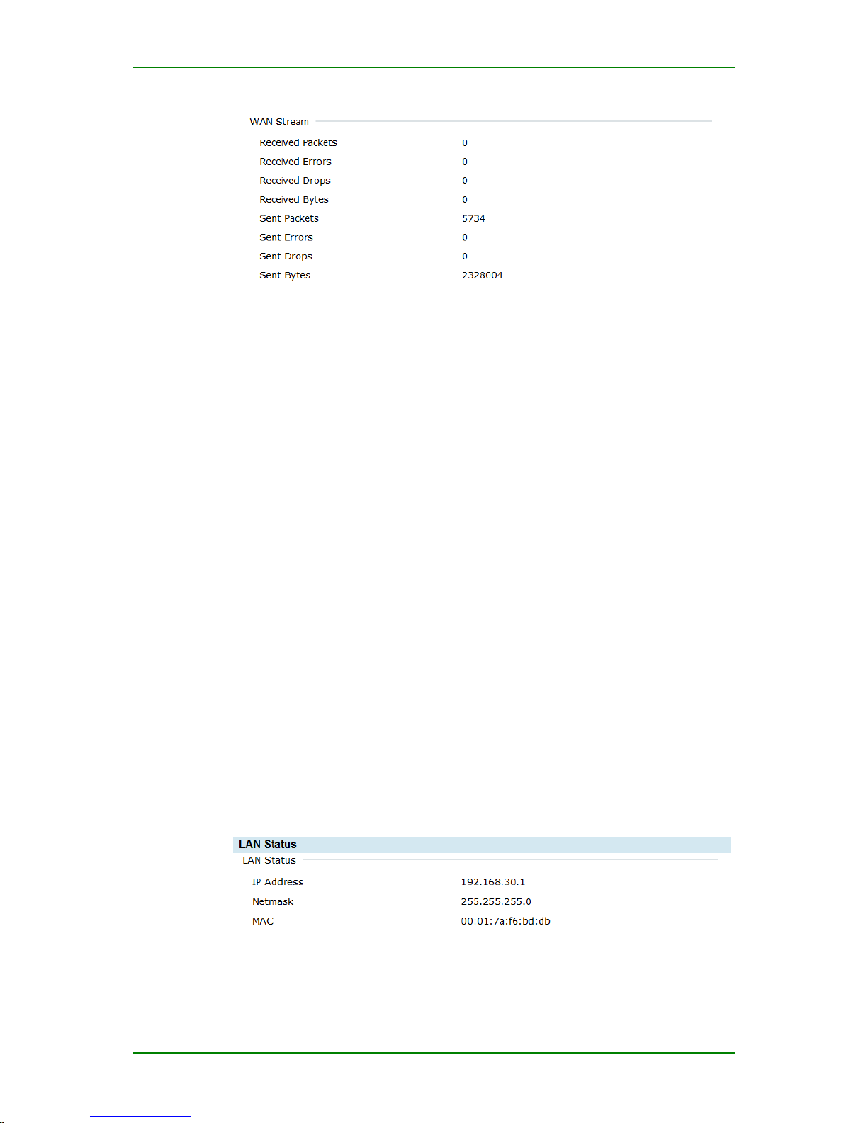
MP1800-10 3G Router User Manual
Maipu Confidential & Proprietary Information Page 85 of 95
WAN traffic information
Received packets: Display the total number of the packets received by
the WAN port
Received Errors: Display the number of the error packets received by
the WAN port
Received Drops: Display the number of the dropped packets received by
WAN port
Received Bytes: Display the number of the bytes received by the WAN
port
Sent Packets: Display the total number of the packets sent by the WAN
port
Sent Errors: Display the number of the error packets sent by the WAN
port
Sent Drops: Display the number of the dropped packets sent by the WAN
port
Sent Bytes: Display the number of the bytes sent by the WAN port
LAN Status
LAN status displays the current LAN setting, connection status, and the
received and forwarded traffic of the LAN interface. Click Status > LAN
status and you can see the following interface:
LAN status
IP Address: Display the configured IP address of the LAN port.
Page 86
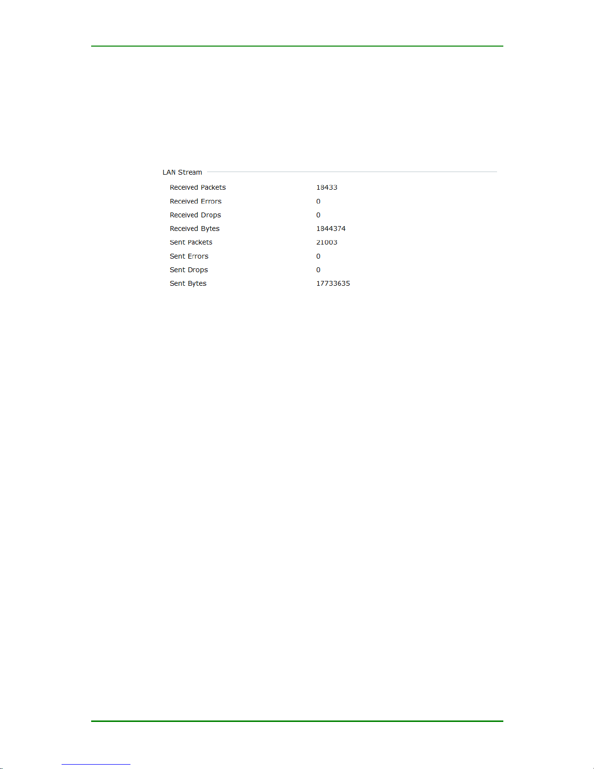
MP1800-10 3G Router User Manual
Maipu Confidential & Proprietary Information Page 86 of 95
Netmask: Display the network address number of the configured LAN
interface.
MAC: Display the physical address of the LAN adapter. Usually, the
address is fixed and unique.
LAN traffic information
Received Packets: Display the total number of the packets received by
the LAN port.
Received Errors: Display the number of the error packets received by
the LAN port.
Received Drops: Display the number of the dropped packets received by
the LAN port.
Received Bytes: Display the number of the bytes received by the LAN
port.
Sent Packets: Display the total number of the packets sent by the LAN
port.
Sent Errors: Display the number of the error packets sent by the LAN
port.
Sent Drops: Display the number of the dropped packets sent by the LAN
port.
Sent Bytes: Display the number of the bytes sent by the LAN port.
Route Information
View all route information of MP1800-10 router. Click Status > Route
information to view all route information of the system, as follows:
Page 87
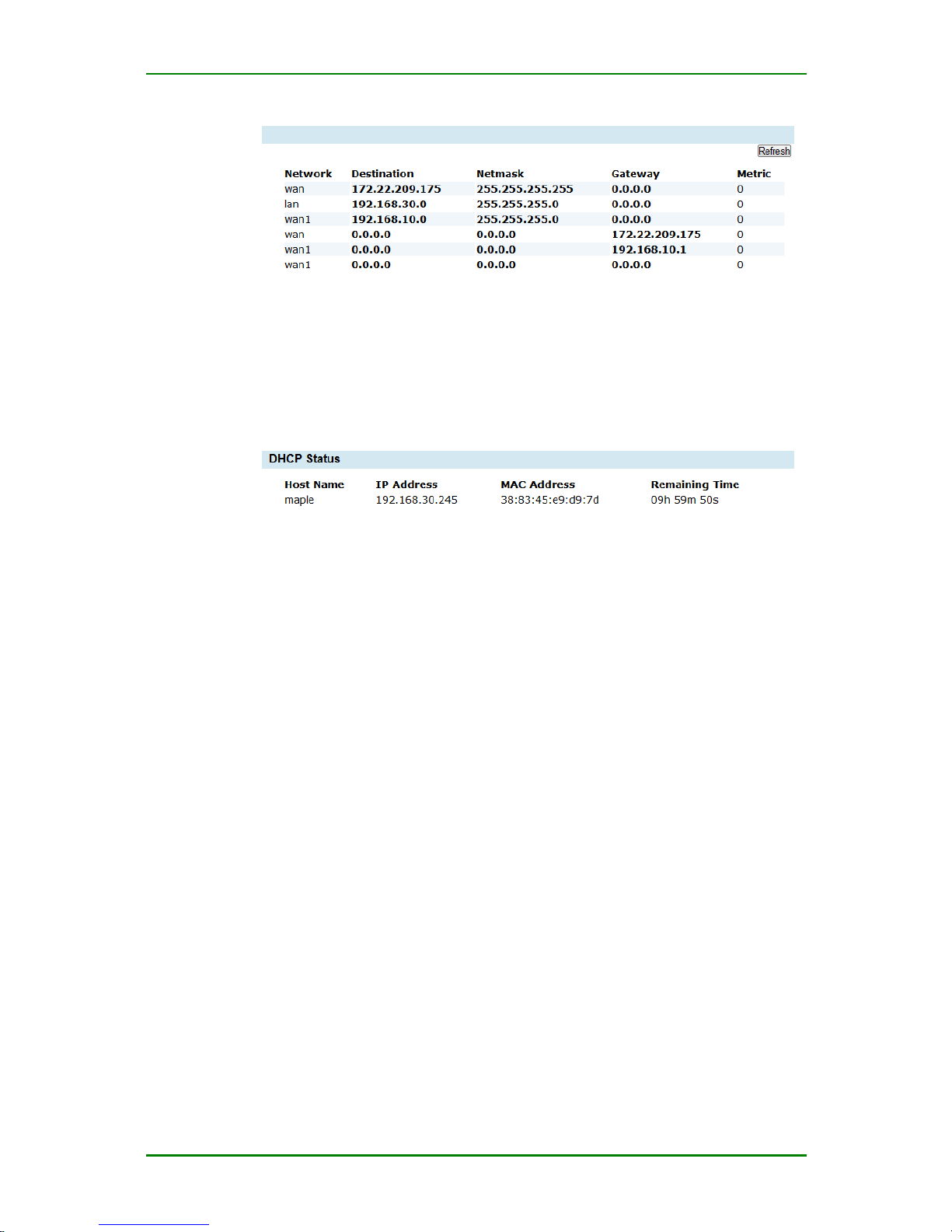
MP1800-10 3G Router User Manual
Maipu Confidential & Proprietary Information Page 87 of 95
Route information
DHCP Information
The DHCP client information list displays the IP distribution information of
all DHCP clients of MP1800-10 router. Click Status > DHCP information
and you can see the auto distributed addresses, as follows:
DHCP information
Connection Information
The connection information displays all ARP table information of MP180010 router and the connection information of the current system. Click
Status > Connection information and you can see the status of the
system connection, as follows:
Page 88
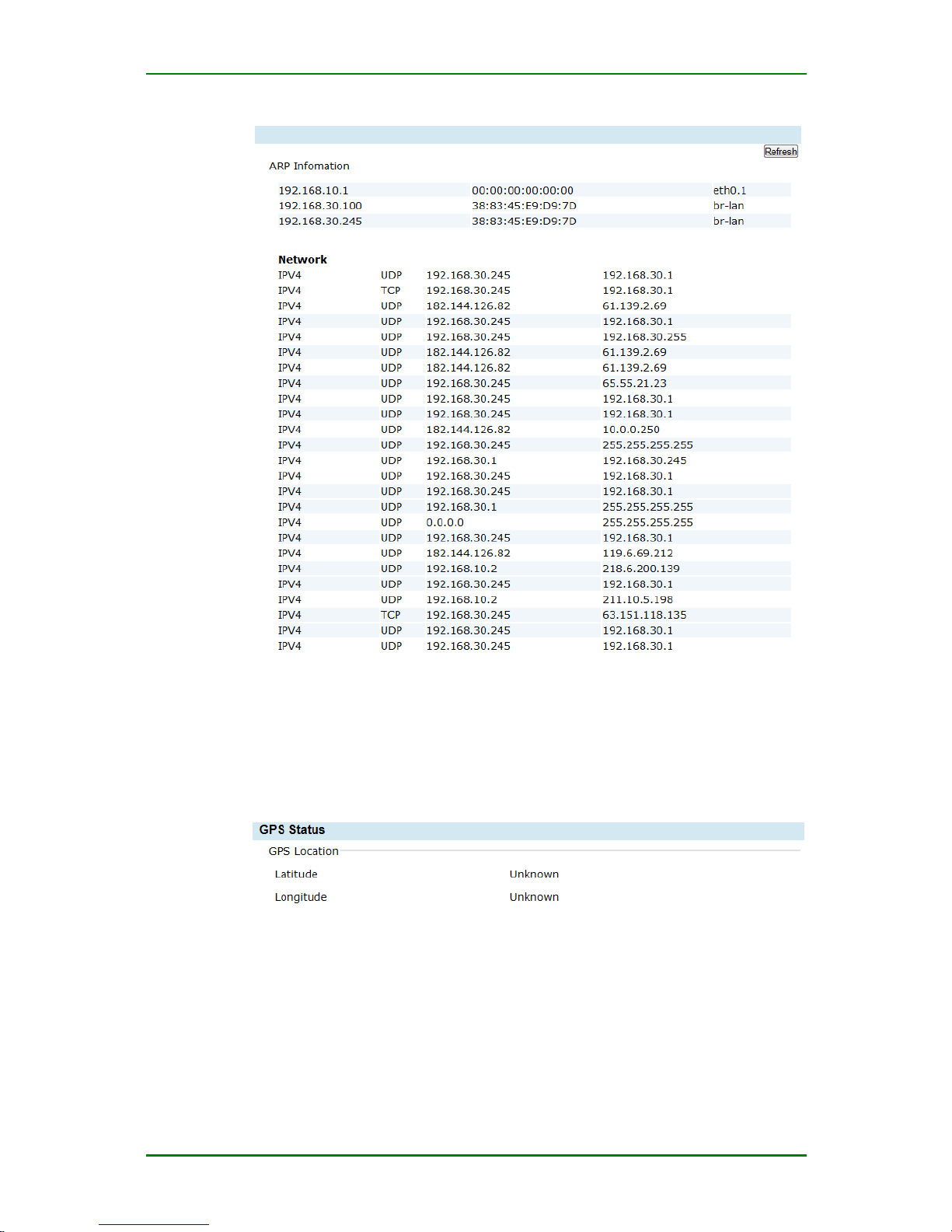
MP1800-10 3G Router User Manual
Maipu Confidential & Proprietary Information Page 88 of 95
Connection information
GPS Status
This screen provides the longitude and latitude information of the devices
location if GPS signal can be received:
GPS Status
Page 89

MP1800-10 3G Router User Manual
Maipu Confidential & Proprietary Information Page 89 of 95
CLI
After logging in via the CLI of the device (serial port, Telnet, SSH), you can use
the command to perform the basic viewing and configuration operations,
including:
System
Interface
3G
IPSec
Route
Firewall
DHCP&VRRP
System
Command
Description
Configuration Mode
show {arp | process |
version | clock }
View the system information
show otp key
Get the login otp
intermediate value
show logging {buffer |
realtime}
View the system running logs
Reload
Restart the device
Exit
Log out the device
active device
Activate the locked device
login
key
Log into the shell command
line
traceroute
dst
Track the route
ping dst
Network connectivity test
show
Syntax
Description
arp
View the arp table information
process
View the system process information
version
View the system version information
clock
View the system time
show logging
View the real-time and history logs of the system
show logging {buffer | realtime}
Syntax
Description
realtime
View the system real-time logs
buffer
View the system history logs
show otp key
Get the intermediate value of logging into to shell
Page 90

MP1800-10 3G Router User Manual
Maipu Confidential & Proprietary Information Page 90 of 95
login
Log into the shell command line
login key
Syntax
Description
key
Key is the login value after calculation
Interface
Command
Description
Configuration Mode
show interface
View the interface
information of the system
show interface
ifname
[configure | status]
View the configuration or
status of the interface
ip address
address mask
Configure the IP address of
the interface
config-if-wan#
ip address
Syntax
Description
address mask
Address refers to the IP address of the
interface; mask refers to the network mask of
the interface.
show interface
View the information of all interfaces or one interface
show interface ifname [configure | status]
ifname can be wan, lan, wan1, and lan1
Syntax
Description
ifname
configure
View the interface configuration information
ifname
status
Just used to view the ppp interface status.
The command is wan status
3G
Command
Description
Configuration Mode
sms sendto
phone-num
content
Send short message
config#
sms gateway
phone-num
Set the number of the short
message gateway
config#
show device usb
View the usb device
information
show sms gateway
View the number of the short
message gateway
show ppp
View the ppp configuration
information
show configure
modularname
View the module
configuration information
sms sendto
Page 91

MP1800-10 3G Router User Manual
Maipu Confidential & Proprietary Information Page 91 of 95
Send content to phone-num
Syntax
Description
phone-num content
phone-num refers to the destination number;
content refers to the content of the short
message.
Note: Before the telephone number, there needs to be county code
sometimes, such as China +86. Here, the whole phone-num should be as
follows: +8613912345678.
sms gateway
Set the number of the short message gateway
Syntax
Description
phone-num
phone-num indicates the number of the short
message gateway, such as 13912345678
show device usb
View the usb device information in the system
show sms gateway
View the number of the short message gateway
show ppp
View the PPP configuration information
show configure
View the configuration information of the module
show configure modularname
Syntax
Description
modularname
The module name, such as raccoon, network,
and firewall
IPSec
Command
Description
Configuration Mode
show crypto ca {crls |
certificates}
View the certificate
show crypto {ike | ipsec}
sa
View the sa information
show crypto policy
View the ipsec policy
information
clear crypto {ike | ipsec}
sa
Clear the sa information
crypto ipsec restart
Restart ipsec
config#
no crypto ca certificate
name
commonname
Delete the certificate
according to the CN value of
the certificate
config#
no crypto ca certificate
type {all | crl | my|root}
Delete the certificate
according to the certificate
config#
Page 92

MP1800-10 3G Router User Manual
Maipu Confidential & Proprietary Information Page 92 of 95
type
show crypto ca
View the certificate information in the system
Syntax
Description
crls
View the ca certificate
certificates
View the device certificate
show crypto
View the ike or ipsec sa information
show crypto {ike | ipsec} sa
Syntax
Description
ike sa
View the ike sa information
ipsec sa
View the ipsec sa information
no crypto ca certificate name
Delete the certificate according to the CN domain value in the subject
name of the certificate
no crypto ca certificate name commonname
Syntax
Description
commonname
The CN value in certificate subject
no crypto ca certificate type
Delete the certificate according to the type
no crypto ca certificate type {all | crl | my|root}
Syntax
Description
all
Delete all certificates and crl files in the
system
crl
Delete all crl files
my
Delete all device certificates in the system
root
Delete all center certificates in the system
Route
Command
Description
Configuration Mode
show ip route [static]
View the route information of
the system
#
ip route
netaddr mask
gateway
Add route information
config#
ip route
Add route
ip route netaddr mask gateway
Page 93

MP1800-10 3G Router User Manual
Maipu Confidential & Proprietary Information Page 93 of 95
Syntax
Description
netaddr
The destination network address, such as
192.168.10.0.
mask
The network mask, such as 255.255.255.0
gateway
The next-hop IP address
Firewall
Command
Description
Configuration Mode
show firewall {configure |
all | chain
name
| table
name
}
View the firewall
configuration information
show conntrack
View all connection track
information
clear conntrack
Clear the connection track in
the system
show firewall
View the firewall configuration information
show firewall {configure | all | chain name | table name}
Syntax
Description
configure
all
chain
name
table
name
View the firewall configuration
View all rules of the firewall
Configure the rules of the name rule chain
View the rules of the name rule table
show conntrack
View the connection track information of the system
clear conntrack
Clear all link tracks in the system
DHCP&VRRP
Command
Description
Configuration Mode
show ip dhcp configure
View the dhcp configuration
show vrrp configure
View the vrrp configuration
Page 94

MP1800-10 3G Router User Manual
Maipu Confidential & Proprietary Information Page 94 of 95
Appendix
APN Access Point Name
CDMA Code Division Multiple Access
DHCP Dynamic Host Configuration Protocol
DNS Domain Name System
GPRS General Packet Radio Service
GSM Global System for Mobile Communications
IP Internet Protocol
IPv4 IP version 4
IPv6 IP version 6
IPSEC IP Secure Protocol
L2TP Layer 2 Tunneling Protocol
MTU Maximum Transmission Unit
NAT Network Address Translation
NTP Network Time Protocol
PAP Password Authentication Protocol
QoS Quality of Service
RADIUS Remote Authentication Dial In User Service
RIP Routing Information Protocol
SIM Subscriber Identity Module
SMS Short Message Service
SMSC Short Message Service Center
SNMP Simple Network Management Protocol
TCP Transmission Control Protocol
Page 95

MP1800-10 3G Router User Manual
Maipu Confidential & Proprietary Information Page 95 of 95
TDMA Time Division Multiple Access
UDP User Datagram Protocol
UIM User Identity Module
UMTS Universal Mobile Telecommunication System
VPN Virtual Private Network
VRRP Virtual Router Redundancy Protocol
WAN Wide Area Network
WAP Wireless Application Protocol
 Loading...