

Maipu MP1800 Installation Manual

MP1800 Router Inst all Manual
V1.2
Maipu Communication Technology Co., Ltd
No. 16, Jiuxing Avenue
Hi-tech Park
Chengdu, Sichuan Province
People’s Republic of China - 610041
Tel: (86) 28-85148850, 85148041
Fax: (86) 28-85148948, 85148139
URL: http://
www.maipu.com
Email: overseas@maipu.com
Maipu Confidential & Proprietary Information Page 1 of 55

MP1800 Router Install Manual V1.2
All rights reserved. Printed in the People’s Republic of China.
No part of this document may be reproduced, transmitted, transcribed, stored in a retrieval system, or translated into any
language or computer language, in any form or by any means, electronic, mechanical, magnetic, optical, chemical, manual
or otherwise without the prior written consent of Maipu Communication Technology Co., Ltd.
Maipu makes no representations or warranties with respect to this document contents and specifically disclaims any implied
warranties of merchantability or fitness for any specific purpose. Further, Maipu reserves the right to revise this document
and to make changes from time to time in its content without being obligated to notify any person of such revisions or
changes.
Maipu values and appreciates comments you may have concerning our products or this document. Please address comments
to:
Maipu Communication Technology Co., Ltd
No. 16, Jiuxing Avenue
Hi-tech Park
Chengdu, Sichuan Province
People’s Republic of China - 610041
Tel: (86) 28-85148850, 85148041
Fax: (86) 28-85148948, 85148139
URL: http://
www.maipu.com
Email: overseas@maipu.com
All other products or services mentioned herein may be registered trademarks, trademarks, or service marks of their
respective manufacturers, companies, or organizations.
Maipu Confidential & Proprietary Information Page 2 of 55

MP1800 Router Install Manual V1.2
Maipu Feedback Form
Your opinion helps us improve the quality of our product documentation
and offer better services. Please fax your comments and suggestions to
(86) 28-85148948, 85148139 or email to
overseas@maipu.com.
Document Title MP1800 Router Install Manual V1.2
Product
Version
Document
Revision
Number
1.2
Presentation:
(Introductions, procedures, illustrations, completeness, arrangement, appearance)
Good Fair Average Poor
Accessibility:
(Contents, index, headings, numbering)
Good Fair Average Poor
Evaluate this
document
Editorial:
(Language, vocabulary, readability, clarity, technical accuracy, content)
Good Fair Average Poor
Your
suggestions to
improve the
document
Please check suggestions to improve this document:
Improve introduction Make more concise
Improve Contents Add more step-by-step procedures/tutorials
Improve arrangement Add more technical information
Include images Make it less technical
Add more detail Improve index
If you wish to be contacted, complete the following:
Name Company
Postcode Address
Telephone E-mail
Maipu Confidential & Proprietary Information Page 3 of 55

MP1800 Router Install Manual V1.2
Content s
Production Introduction.............................................................................6
Product Features ....................................................................................................6
Hardware Features .................................................................................................7
MP1800 Series Multi-service Router Appearance.......................................................................7
Front and Back Panels of MP1800 Series Multi-service Router....................................................7
System Description of MP1800 Series Multi-service Access Router ...........................................13
Slots of MP1800 Series Multi-service Access Router.................................................................14
Modules.................................................................................................... 16
Sync/Async Serial Interface Module (SAE) Series.....................................................16
1-port High-speed V.24/V.35 Serial Module (1SAE).................................................................16
Channelized E1 Module (CE1)................................................................................ 17
1-port Channelized E1 Module (1CE1) ....................................................................................17
Non-channelized E1 (E1) Series.............................................................................18
1-port Non-channelized E1 Module (1E1)................................................................................18
IP Phone Module (VOP/VOS) Series........................................................................ 19
IP Phone Module of 1-port IP Phone (1VOP) ...........................................................................19
IP Phone Module of 2-port Phone (2VOP) ...............................................................................20
IP Phone Module of 1-port Switch (1VOS)...............................................................................21
IP Phone Module of 2-port Switch (2VOS)...............................................................................22
ISDN S/T Module (STA) Series............................................................................... 23
1-port ISDN S/T Module (1STA).............................................................................................23
Asyn Serial Module (A) Series................................................................................24
8-asyn Serial Module (8AX) ...................................................................................................24
ADSL Module........................................................................................................25
G.SHDSL Series Module ........................................................................................ 26
2-port G.SHDSL ....................................................................................................................26
4-port G.SHDSL ....................................................................................................................26
Interface Attributes of G.SHDSL Interface Module ...................................................................27
4S1O Module .......................................................................................................27
3G Series Module..................................................................................................28
RM2-3G-CDMA......................................................................................................................29
RM2-3G-GSM........................................................................................................................29
RM2-3G-TD...........................................................................................................................30
Maipu Confidential & Proprietary Information Page 4 of 55

MP1800 Router Install Manual V1.2
Install USIM Card ..................................................................................................................31
SM1 Module.........................................................................................................31
RM2-SM1 Module Appearance................................................................................................31
Installation Preparations ........................................................................ 32
Security Suggestions ............................................................................................32
Environment Requirements ................................................................................... 32
Temperature and Humidity....................................................................................................33
Dust-free Environment ..........................................................................................................34
Anti-static .............................................................................................................................34
Electromagnetic Environment Requirements...........................................................................35
Anti-lightning ........................................................................................................................35
Check Routers & Accessories ................................................................................. 36
Tools & Equipment................................................................................................ 36
System Installation................................................................................. 37
Preparations......................................................................................................... 37
Tools ....................................................................................................................................37
Cabinet Installation................................................................................................................37
Install Device on Desk........................................................................................... 41
Install Device on Wall............................................................................................ 41
Connect Host Cables............................................................................................. 42
Connect Protection Ground Wire ............................................................................43
Connect Power Supply ..........................................................................................43
Module Installation................................................................................................45
Connect 1SAE Interface Cable................................................................................................45
Connect 1CE1/1E1 Module Interface Cable .............................................................................47
Connect 1VOP/2VOP Module Interface Cable ..........................................................................48
Connect 1VOS/2VOS Module Interface Cable..........................................................................48
Connect 1ST Module Interface Cable ......................................................................................49
Connect 8AX Module Interface Cable......................................................................................49
Connect ADSL Module Interface Cable....................................................................................49
Connect G.SHDSL Module Interface Cable ..............................................................................50
Connect 4S1O Module Interface Cable....................................................................................50
Cables ...................................................................................................... 51
Ethernet Interface Cable........................................................................................51
Ethernet Optical Interface Cable............................................................................. 52
Console Port Cable................................................................................................ 52
4S1O Interface Distribution Box............................................................................. 53
4S1O Interface Cable............................................................................................53
G.SHDSL Interface Cable.......................................................................................54
Maipu Confidential & Proprietary Information Page 5 of 55

MP1800 Router Install Manual V1.2
Production Introduction
MP1800 is one new multi-service router developed by Maipu, integrating
the routing technology, switching technology, security technology, 3G,
WLAN, traffic control, and network-surf monitoring. It is the MeIN (Multiservice Edge-Intelligent Network) edge network device with high costeffective and complete functions. It adopts the fixed configuration and
modular design. The fixed configuration meets the cable and fiber
broadband access. The modules are expanded to provide 3G, xDSL, PON,
V24/V35, E1/CE1, and ISDN broadband and narrowband access
capabilities, as well as the load balance mechanism of various access
combinations.
Product Features
z Wired and wireless integration, supporting 3G and WLAN access and
inter-connecting with the wired network seamlessly
z Routing and switching integration, supporting tw o Ethernet WAN ports
+ 4/8 Ethernet LAN ports
z Broadband and narrowband integration, supporting N*64K-100M WAN
link interface and directly supporting optical interface uplink
z WAN and LAN integration; the software function completely supports
controlling and managing WAN and LAN in a centralized manner
z Data and voice integration, supporting data multi-serv ice developmen t
and VoIP function and can be expended as IPPBX further
z Information and communication integration, supporting rich value-
added application and network application monitoring
Maipu Confidential & Proprietary Information Page 6 of 55
MP1800 Router Install Manual V1.2
Hardware Features
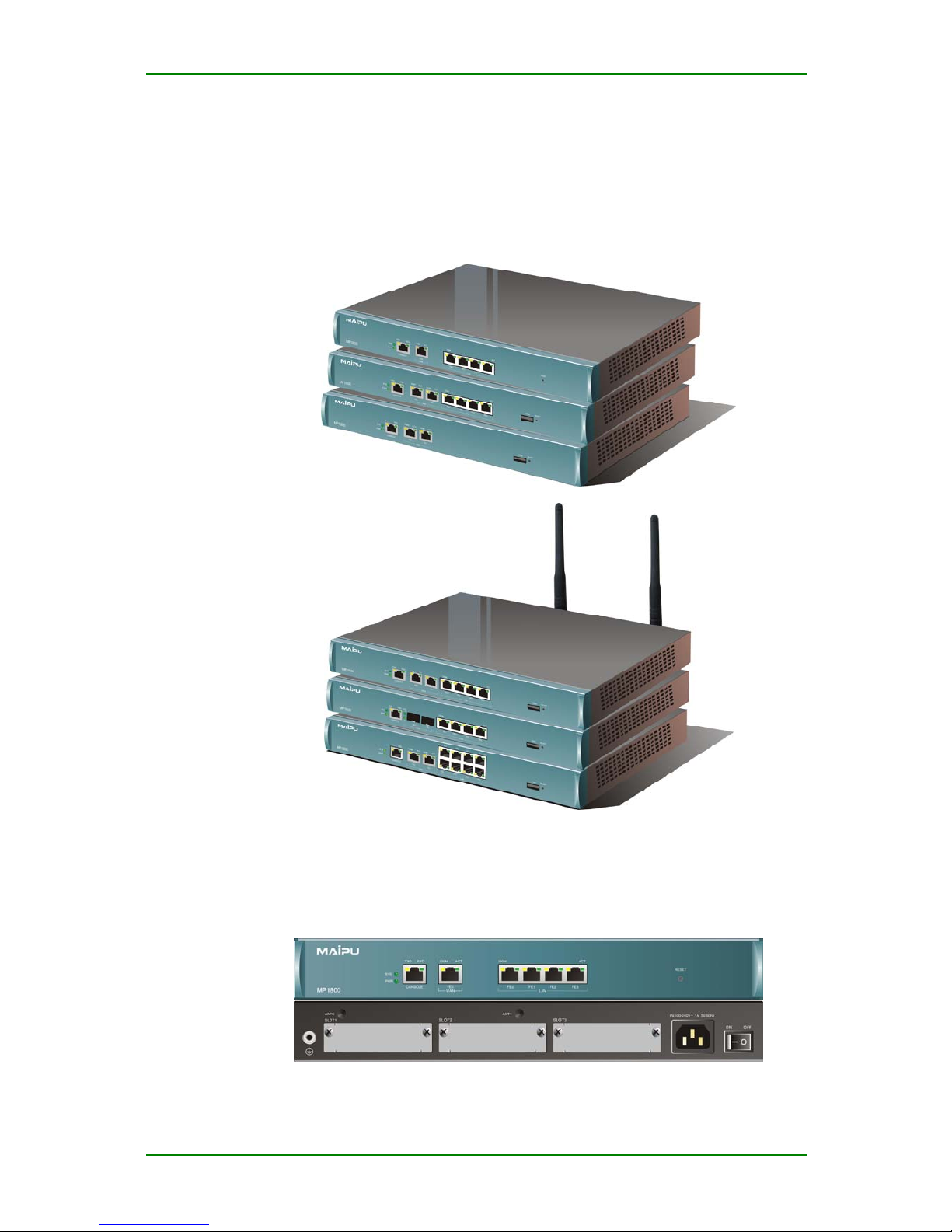
MP1800 Series Multi-service Router
Appearance
MP1800 multi-service access router
Front and Back Panels of MP1800 Series
Multi-service Router
Front and back panels of RM1800-21-AC router
Maipu Confidential & Proprietary Information Page 7 of 55
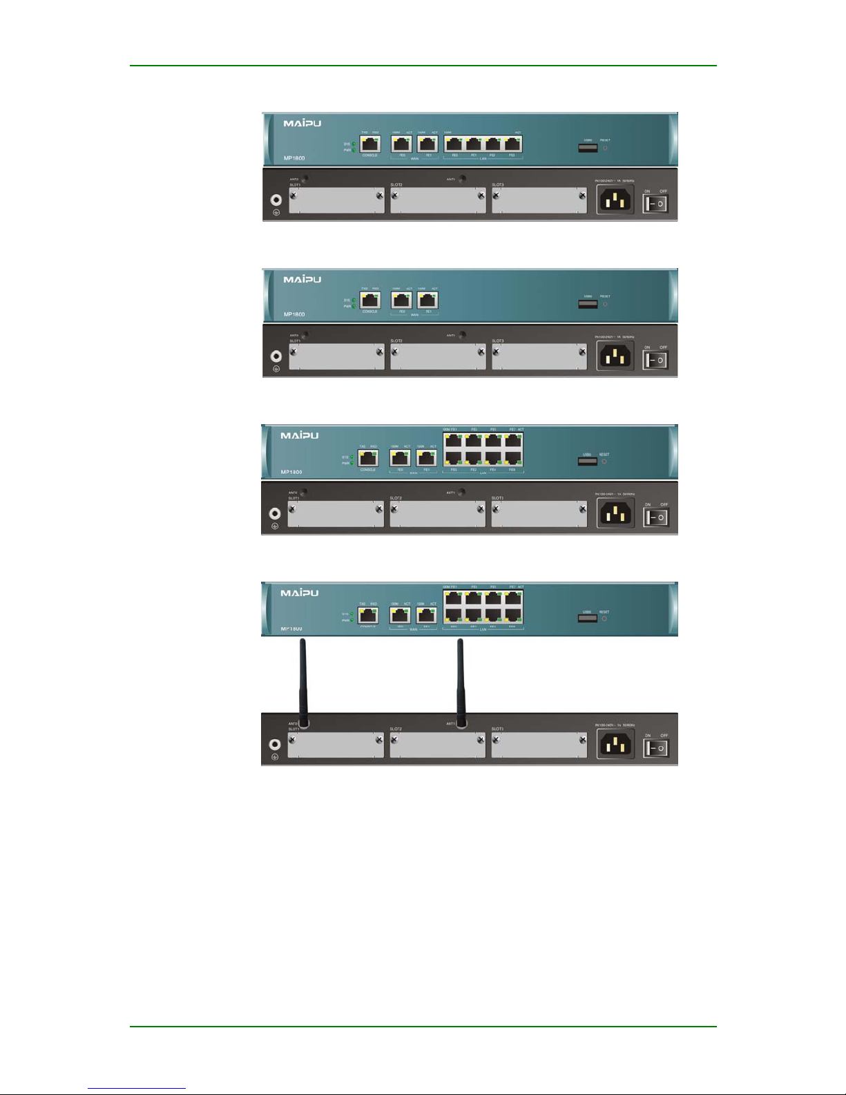
MP1800 Router Install Manual V1.2
Front and back panels of RM1800-22-AC router
Front and back panels of RM1800-23-AC router
Front and back panels of RM1800-31-AC router
Front and back panels of RM1800-31W-AC router
Maipu Confidential & Proprietary Information Page 8 of 55
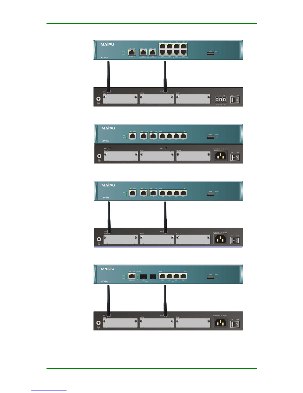
MP1800 Router Install Manual V1.2
Front and back panels of RM1800-31W-DC48 router
Front and back panels of RM1800-35-AC router
Front and back panels of RM1800-35W-AC router
Front and back panels of RM1800-36W-AC router
Maipu Confidential & Proprietary Information Page 9 of 55

MP1800 Router Install Manual V1.2
Front and back panels of RM1800-36-AC router
The meanings of the indicators on the front and back panels of the above
routers:
SYS & PWR (system and power)
z SYS: system status indicator; after the system loads successfully, the
indicator flashes slowly;
z PWR: system power indicator; when the 5V power works normally, the
indicator becomes on;
CONSOLE (console port)
z TXD: data sending indicator of the console port
z RXD: data receiving indicator of the console port
FE0 (WAN Ethernet 0)
z 100M: data rate indicator of 10/100M Ethernet port; on for 100M and
off for 10M;
z LINK/ACT: Ethernet port connection/data receiving and sending
indicator
FE1 (WAN Ethernet 1)
z 100M: data rate indicator of 10/100M Ethernet port; on for 100M and
off for 10M;
z LINK/ACT: Ethernet port connection/data receiving and sending
indicator
LAN Ethernet port 0-7
RM1800-21-AC, RM1800-22-AC, RM1800-23-AC, RM1800-31-AC,
RM1800-31W-AC, RM1800-31W-DC48:
z Yellow light (left): data rate indicator of 10/100M Ethern et port; on for
100M and off for 10M;
z Green light (right): data receiving and sending indicator of Ethernet
port
Maipu Confidential & Proprietary Information Page 10 of 55

MP1800 Router Install Manual V1.2
RM1800-35-AC, RM1800-35W-AC, RM1800-36-AC, RM1800-36W-AC:
z Yellow light (left): data rate indicator of 100/1000M Ethernet port; on
for 1000M and off for 100M;
z Green light (right): data receiving and sending indicator of Ethernet port
The description of the interfaces:
The interfaces on the front panel of MP1800 series router
Device Type
Interface
Interface
Type
Description
CONSOLE RJ45 Console port
WAN port RJ45
One 100M Ethernet electric
port
RM1800-21-AC
LAN port RJ45
Four 100M Ethernet electric
ports
CONSOLE RJ45 Console port
WAN port RJ45
Two 100M Ethernet electric
ports
LAN port RJ45
Four 100M Ethernet electric
ports
RM1800-22-AC
USB port
USB
interface
One USB interface
CONSOLE RJ45 Console port
WAN port RJ45
Two 100M Ethernet electric
ports
RM1800-23-AC
USB port
USB
interface
One USB interface
CONSOLE RJ45 Console port
WAN port RJ45
Two 100M Ethernet electric
ports
LAN port RJ45 Eight 100M Ethernet ports
RM1800-31-AC
RM1800-31W-AC
RM1800-31W-DC48
USB port
USB
interface
One USB interface
Maipu Confidential & Proprietary Information Page 11 of 55

MP1800 Router Install Manual V1.2
CONSOLE RJ45 Console port
WAN port RJ45
Two 100M Ethernet electric
ports
LAN port RJ45
Four 1000M Ethernet electric
ports
RM1800-35-AC
RM1800-35W-AC
USB port
USB
interface
One USB interface
CONSOLE RJ45 Console port
WAN port SFP
Two 100M Ethernet electric
ports
LAN port RJ45
Four 1000M Ethernet electric
ports
RM1800-36-AC
RM1800-36W-AC
USB port
USB
interface
One USB interface
The interfaces on the back panel of the MP1800 series router
Interface Interface Type Description Corresponding slot
ON/OFF
The power switch,
ON or OFF
AC: 100-240V
Max. Current: 1A
IN
DC: -57- -40V
Max. current: 2A
SLOT3
The interface type
depends on the
interface module.
Bus slot Multi-function module
SLOT2
The interface type
depends on the
interface module.
Bus slot Multi-function module
SLOT1
The interface type
depends on the
interface module.
Bus slot Multi-function module
Maipu Confidential & Proprietary Information Page 12 of 55

MP1800 Router Install Manual V1.2
System Description of MP1800 Series
Multi-service Access Router
The basic configuration and working environment of MP1800 router are as
follows:
MP1800 router system
Item Description
Console port One (RJ45), asyn DTE working mode
Ethernet port
Two 10/100M fast Ethernet ports (RJ45), except for RM1800-21-AC
One 10/100M fast Ethernet port (RJ45), RM1800-21-AC
High-speed multi-
function slot
Three high-speed multi-function slots
USB high-speed
interface
One (except for RM1800-21-AC)
Processor High-speed RISC processor
FLASH 32Mbyte
SDRAM 256Mbyte
RM1800-21-AC
RM1800-22-AC
RM1800-23-AC
RM1800-35-AC
RM1800-35W-AC
RM1800-36-AC
RM1800-36W-AC
340 x 260 x 43.8
Domension
(W×D×H)
RM1800-31-AC
RM1800-31W-AC
RM1800-31W-DC48
340 x 300 x 43.8
Max. weight <4.5 Kg
AC 100-240V, 50/60Hz
Input voltage
DC -57- -40V
Environment
temperature
Working temperature for a long term: 5~40℃
Working temperature for a short term (48 hours): -5~45℃
Environment
humidity
10-90% no-condensing
Maipu Confidential & Proprietary Information Page 13 of 55

MP1800 Router Install Manual V1.2
Rated power 50W
Max. power
36W±10% (RM1800-31-AC, RM1800-31W-AC, RM1800-31W-DC48);
30W±10% (RM1800-21-AC, RM1800-22-AC, RM1800-23-AC, RM1800-
35-AC, RM1800-35W-AC);
26W±10% (RM1800-36-AC, RM1800-36W-AC)
Slots of MP1800 Series Multi-service
Access Router
Slots of MP1800 series router
Device Type Description
RM1800-21-AC
RM2-1STA, 8AX, 1/2VoS, 1/2VoP, 4S1O, and SM1 modules are suitable
for slot 1, slot 2, and slot 3.
RM2-1SAE module is suitable for slot 1 and slot 2.
RM2-1E1 and 1CE1 modules are suitable for slot 1.
RM2-1ADSL and xGSHDSL modules are suitable for slot 2.
RM1800-22-AC
RM1800-23-AC
RM2-1STA, 8AX, 1/2VoS, 1/2VoP, 4S1O, and SM1 modules are suitable
for slot 1, slot 2, and slot 3.
RM2-1SAE module is suitable for slot 1 and slot 2.
RM2-1E1 and 1CE1 modules are suitable for slot 1.
RM2-1ADSL and xGSHDSL modules are suitable for slot 2., but when the
modules are inserted, WAN1 (FE1) on the front panel is unavailable.
The 3G module of RM2 is suitable for slot 3.
RM1800-35W-AC
RM1800-35-AC
RM1800-31-AC
RM1800-31W-AC
RM1800-31W-DC48
RM2-1STA, 8AX, 1/2VoS, 1/2VoP, 4S1O, and SM1 modules are suitable
for slot 1, slot 2, and slot 3.
RM2-1SAE module is suitable for slot 1 and slot 2.
RM2-1E1 and 1CE1 modules are suitable for slot 1.
RM2-1ADSL and xGSHDSL modules are suitable for slot 2., but when the
modules are inserted, WAN1 (FE1) on the front panel is unavailable.
The 3G module of RM2 is suitable for slot 3.
RM1800-36W-AC
RM1800-36-AC
RM2-1STA, 8AX, 1/2VoS, 1/2VoP, 4S1O, and SM1 modules are suitable
for slot 1, slot 2, and slot 3.
RM2-1SAE module is suitable for slot 1 and slot 2.
RM2-1E1 and 1CE1 modules are suitable for slot 1.
The 3G module of RM2 is suitable for slot 3.
Note
Maipu Confidential & Proprietary Information Page 14 of 55

MP1800 Router Install Manual V1.2
RM1800-31W-AC, RM1800-31W-DC48, RM1800-35W-AC, and RM180036W-AC support wireless WLAN function. WLAN uses 2.4G frequency band,
so the other devices that use 2.4G frequency band will cause interference
for WLAN. In serious case, WLAN cannot be used. The 2.4G frequencyband devices include Bluetooth device, microwave oven, digital wireless
cordless phone and so on. Therefore, when using WLAN, we should avoid
the interference of the wireless signals.
Maipu Confidential & Proprietary Information Page 15 of 55

MP1800 Router Install Manual V1.2
Modules
MP1800 router is a modular router. It provides three slots. Currently, the
available modules include 1SAE, 1CE1, 1E1, 1STA, 8AX, 1VOP, 2VOP,
1VOS, 2VOS, 4S1O, 1ADSL, 2SHDSL, 4SHDSL, 3G-CDMA, 3G-GSM, 3G-TD,
and SM1. This chapter describes several common modules.
Sync/Async Serial Interface
Module (SAE) Series
1-port High-speed V.24/V.35 Serial Module
(1SAE)
1SAE module is used for MP1800 router. 1SAE completes 1-port
sync/async serial data flow – receiving/sending and processing. The port
operates in synchronous mode:
DCE mode: 2.048Mbps
DTE mode: 8 Mbps
The port in asynchronous mode operates 115.2Kbps. The default working
mode of MP1800 router sync/async serial interface is sync. The sync serial
interface is in DTE or DCE mode. In DTE mode, it receives external DC E
clock such as external sync modem. In DCE mode, the router provides
clock. The V24/V35 mode switch functions via the buttons on the panel.
1SAE Interface Module
1-port high-speed V.24/V.35 serial module (1SAE)
Maipu Confidential & Proprietary Information Page 16 of 55
MP1800 Router Install Manual V1.2
Cables of 1SAE Interface Module
1SAE interface cable is V35 common DTE cable and V24 straight-through
DTE cable.
1SAE Interface Attributes
1-port high-speed V.24/V.35 serial module (1SAE) attributes:
Description Attributes
Sync Async
Tie-in DB25-DB25 DB25-DB25
V.24 V.35 Interface standard & working
mode
DTE
DCE
DTE
DCE
EIA/TIA-232
Minimum baud rate (bps) 1200 1200 300
Maximum baud rate (bps) 128K 8M 115.2K
Dialup
Backup
Supported protocol & service X25
HDLC
PPP
SLIP
FR
LAPB
HDLC
PPP
SLIP
Channelized E1 Module (CE1)
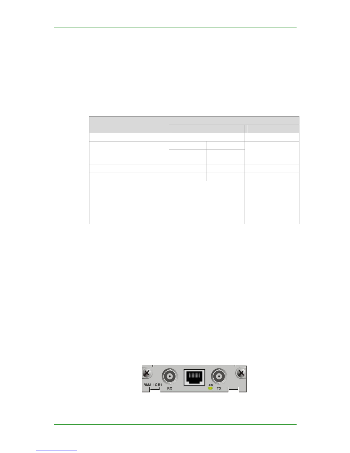
1-port Channelized E1 Module (1CE1)
The 1-port channelized E1 module provides the ports for receiving,
sending and processing 1984K multi-timeslot data flow. As CE1 interface,
it divides slot 1-31 to different groups and each group of timeslots serves
as one interface after binding.
1CE1 Interface Module Appearance &
Indicators
1-port channelized E1 module (1CE1)
Maipu Confidential & Proprietary Information Page 17 of 55
 Loading...