

Page 1

Page 2

Page 3
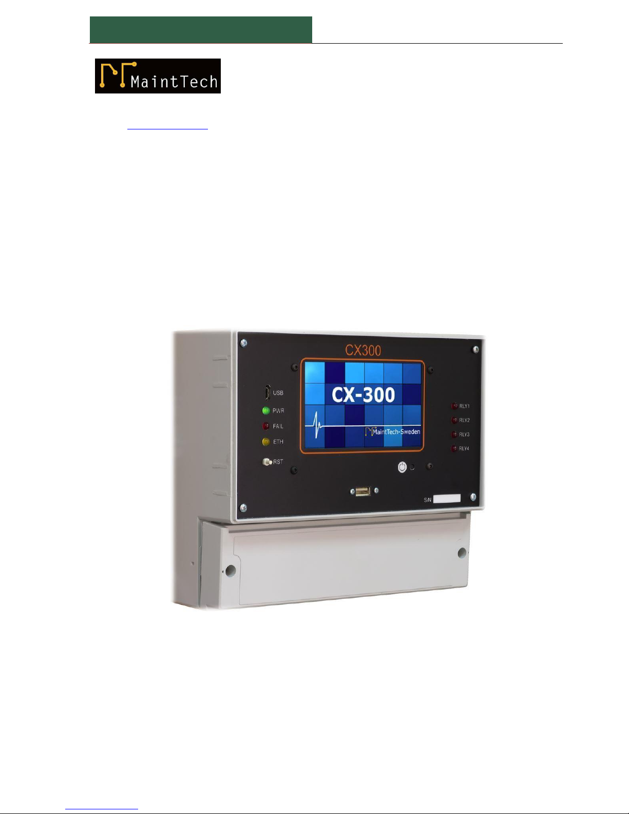
CX300 MODULE – User manual
Doc.2016002
-2-
E-mail: [email protected]
www.mainttech.se
CX300 MODULE
User manual
Document revision: REV. D
DOC. 2016002
June 2017
Page 4

Doc.2016002
CX300 MODULE – User manual
-3-
Page 5
CX300 MODULE – User manual
Doc.2016002
-4-
Read the user manual carefully before starting to use the unit.
Producer reserves the right to implement changes without prior notice.
Explanation of symbols used in the manual:
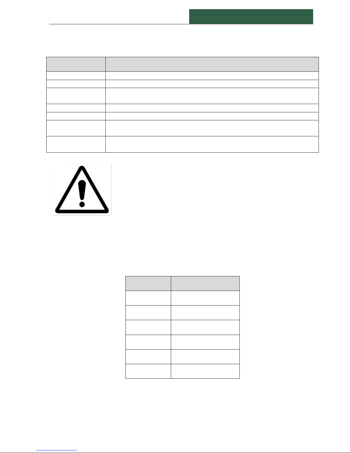
This symbol denotes especially important guidelines concerning the
installation and operation of the device. Not complying with the
guidelines denoted by this symbol may cause an accident, damage
or equipment destruction.
This symbol denotes especially important characteristics of the unit.
Read any information regarding this symbol carefully
IF THE DEVICE IS NOT USED ACCORDING TO THE MANUAL, THE USER IS
RESPONSIBLE FOR POSSIBLE DAMAGES.
Page 6

Doc.2016002
CX300 MODULE – User manual
-5-
Page 7

CX300 MODULE – User manual
Doc.2016002
-6-
Contents
CX300 User Manual
1. BASIC REQUIREMENTS AND USER SAFETY ............................................................................... 8
2. GENERAL CHARACTERISTICS .................................................................................................... 9
3. TECHNICAL DATA .................................................................................................................... 10
4. ORDER CODE .......................................................................................................................... 11
5. TYPICAL APPLICATION ............................................................................................................ 12
5.1. STAND-ALONE SIMPLE APPLICATION ............................................................................. 12
5.2. NETWORK APPLICATION ................................................................................................. 13
5.3. CX-MON300 Monitoring Software ................................................................................. 13
6. DEVICE INSTALLATION ............................................................................................................ 14
6.1. UNPACKING..................................................................................................................... 15
6.2. ASSEMBLY ....................................................................................................................... 16
6.3. CONNECTION TERMINALS .............................................................................................. 17
7. HARDWARE CONFIGURATION ................................................................................................ 20
7.1. ACCELEROMETER POWER ............................................................................................... 20
7.2. VOLTAGE FOR SPEED SENSOR ........................................................................................ 20
8. SOFTWARE CONFIGURATION ................................................................................................. 21
8.1. GENERAL UNIT CONFIGURATION ................................................................................... 21
8.2. VIBRATION AND BE MEASUREMENTS ............................................................................ 21
8.3. TEMPERATURE MEASUREMENTS ................................................................................... 22
8.4. SPEED MEASUREMENT ................................................................................................... 23
9. NORMAL STARTING SEQUENCE ............................................................................................. 24
10. CX300 LED INDICATOR ........................................................................................................... 24
11. TROUBLESHOOTING ............................................................................................................... 25
12. MAINTENANCE ....................................................................................................................... 25
Assigning Private Network IP Addresses to the CX300 Modules ........................... 26
Page 8

Doc.2016002
CX300 MODULE – User manual
-7-
Page 9
CX300 MODULE – User manual
Doc.2016002
-8-
1. BASIC REQUIREMENTS AND USER SAFETY
The manufacturer is not responsible for any damages caused by inappropriate
installation, not maintaining the proper environmental conditions and using the
unit contrary to its assignment.
Only qualified personnel should conduct installation. During installation, all
available safety requirements should be considered. The fitter is responsible for
executing the installation according to this manual, local safety and EMC
regulations.
The unit must be properly set-up, according to the application. Incorrect
configuration can cause defective operation, which can lead to unit damage or
an accident.
If in the case of a unit malfunction, there is a risk of a serious threat to the safety
of people or property additional, independent systems and solutions to prevent
such a threat must be used.
Neighboring and connected equipment must meet the appropriate of
appropriate standards and regulations concerning safety and be equipped with
adequate overvoltage and interference filters.
Do not attempt to disassemble, repair, or modify the unit yourself. The unit has
no user serviceable parts. Defective units must be disconnected and submitted
for repairs at an authorized service center.
In order to minimize fire or electric shock hazard, the unit must be protected
against atmospheric precipitation and excessive humidity.
Do not use the unit in areas threatened with excessive shocks, vibrations, dust,
humidity, corrosive gasses, and oils.
Do not use the unit in areas where there is risk of explosions.
Do not use the unit in areas with significant temperature variations, exposure to
condensation or ice.
Do not use the unit in areas exposed to direct sunlight.
Make sure that the ambient temperature (e.g. inside the control box) does not
exceed the recommended values. In such cases, forced cooling of the unit must
be considered (e.g. by using a ventilator).
THE USE OF TOUCH-SCREEN
Do not use pointers with sharp edges (like tips of pencils and pens, knifes,
scissors, needles, wires, nails, screws, bolts etc.) while working with touchscreen. It is strongly recommended to use a special stylus made of plastic or
another soft material with round ends. The display of the CX300 should also be
protected against aggressive substances and extremely high and low
temperatures.
Page 10

Doc.2016002
CX300 MODULE – User manual
-9-
2. GENERAL CHARACTERISTICS
The CX300 is a complete vibration & temperature monitoring and protection system in a single
enclosure. The CX300 is a sophisticated multichannel unit, which allows simultaneous
measurement, visualization, and control of numerous channels. This device can operate
autonomously or with cooperation with external PC software.
Essential features of CX300 are listed and briefly described below.
Compact multi-channel vibration and temperature data acquisition system;
Four vibration input channels, suitable for ICP Accelerometers, velocity and displacement
sensors;
High frequency range and resolution, suitable for wide variation type of machines;
Fast acquisition time, high sampling rate;
4 to 20 mA output for all vibration channels;
Four temperature input channels for PT100 RTD (2 or 3-wires);
One speed measurement channel;
Bearing fault estimator(BE);
Two galvanic isolate digital input;
Protection system(CX300) with four software programmable output relay;
Programmable alarm multiplier during start-up;
Optional local LCD Display (3.5"TFT,320x240pixels,touch-screen navigation);
Communication:1xUSBDevice,1xEthernet100Mb;
Wide range for power supply (18to36Vdc);
Low power consumption;
IP65 protection.
Page 11
CX300 MODULE – User manual
Doc.2016002
-10-
3. TECHNICAL DATA
Table 1
Power supply voltage
18V to +36V DC (Typically +24 V ±10%)
Power consumption
6 VA typical; 10 VA max.
External Fuse (required)
T -type, max. 2 A
Vibration inputs
Accelerometer, Velocity and Displacement Sensors
Channels
4
Max. frequency
6400 Hz (configurable)
Amplitude range
20 V p-p
Spectrum lines
Up to 6400
Data acquisition
12 channels simultaneous (three gains for each input, no autoranging required)
A/D resolution
16 bits
Spectrum resolution
Selectable (0.5, 1 or 2 Hz)
Total value HPF
Selectable (none, 5 or 10 Hz)
Total value LPF
Selectable (from 200 to 6400 Hz)
Accelerometers supply
4 mA @ 24 V dc
Bearing estimator
Bearing Energy Coefficient (BE)
BE HPF
500 Hz
Temperature inputs
4 X PT100 (2 or 3 wires)
Channels
4
Temperature range
Selectable (Min. -50ºC, Max 300 ºC)
Speed input
1
Speed range
1 Hz to 5 KHz
Digital inputs
2 (Start-up and Relay Reset), optocoupled
Power consumption
7,5 mA / 24V,
Isolation
500V DC
Outputs
Analog
4 X 4-20 mA (max. load 600Ω)
Digital
4 relay
Max. load per relay
5A, cos j = 1 (resistive load)
Max. voltage switched by relay
250V AC
Page 12
Doc.2016002
CX300 MODULE – User manual
-11-
Isolation strength between relays
1 min. @ 630V AC
Communication interface
For measurements
1 x Ethernet 100 MB (RJ-45)
For configuration
1 x USB Device (for configuration and firmware upgrade)
Protection
IP 65 (with transparent door)
Working temperature
-10°C to +50°C
Storage temperature
-20°C to +70°C
Humidity
5 to 90% no condensation
Altitude
Up to 2000 meters above sea level
Enclosure
Safety of Information Technology Equipment EN 60950
RoHS directive 2002/95/EC
Flammability Rating
Complies with UL 508
UV resistance
Complies with UL 508
Case style
DIN-Rail
Case material
Polycarbonate
Case dimensions (mm):
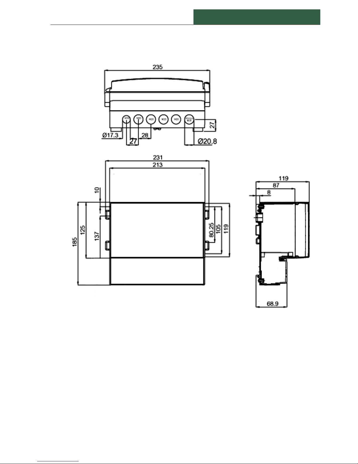
213 x 185 x 120
Display
(Optional) 3.5" graphic TFT, 16-bit color, 320 x 240 pixels,
touchscreen navigation
EMC
PN-EN 61326-1
Safety requirements
According to: PN-EN 61010-1
Installation category: II
Pollution degree: 2
Voltage in relation to ground: 300V AC
Isolation resistance: >20MΩ
Isolation strength between power supply and input/output
terminal: 1min. @ 2300V
NOTE:
Analogic inputs are protected against overvoltage faults as large as ±45V.
Page 13
CX300 MODULE – User manual
Doc.2016002
-12-
4. ORDER CODE
5. TYPICAL APPLICATION
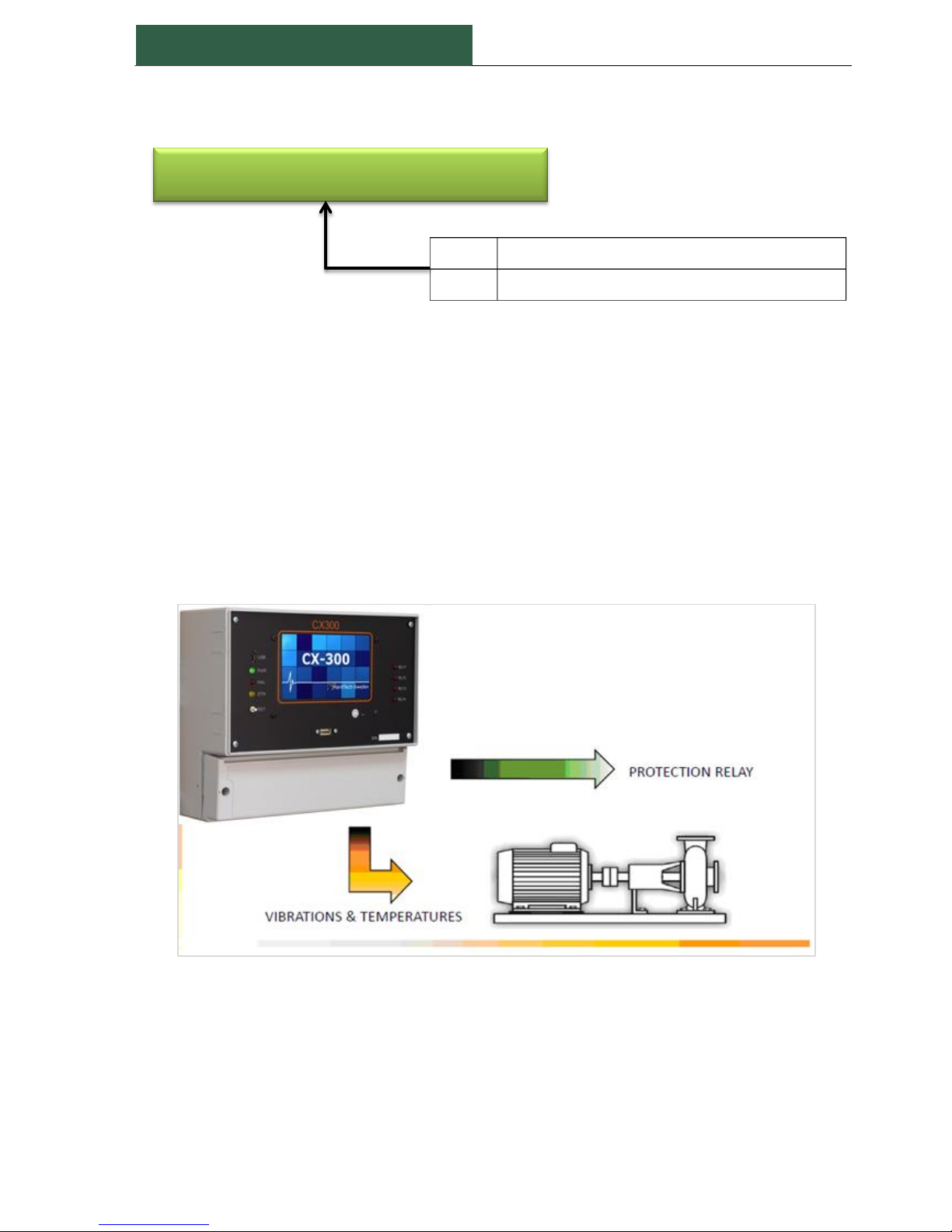
5.1. STAND-ALONE SIMPLE APPLICATION
A single unit can be used independently for a single machine.
After hardware and software configuration, the unit work independently.
If the unit is equipped with a local display, the measurement result and alarms status are available
on the screen.
The unit still can be connected, via Ethernet, to a computer running CX-MON300 application.
Figure 1 - Stand-alone typically application
CX300 – Module with touchscreen display
CX200 – Module without display
200
with 4×RTD, 4×4÷20 mA outputs and 4 relays
300
with 4×RTD, 4×4÷20 mA outputs and 4 relays
Page 14
Doc.2016002
CX300 MODULE – User manual
-13-
5.2. NETWORK APPLICATION
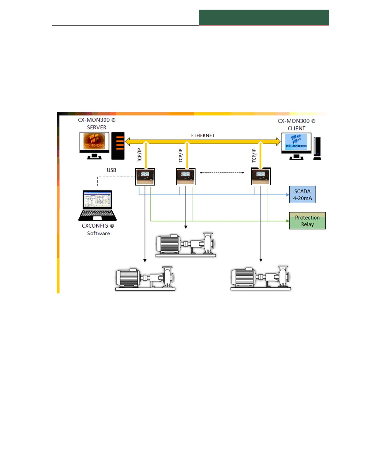
In this configuration, up to 10 units can be connected to a local network and to a computer, when
running CX-MON300 application.
Each unit must have an independent IP Address.
See Addendum A to find more regarding IP allocation.
The CX-MON300 application acts as a network server. The measurements result and alarms can be
visualized in a series of computers running CX-MON300Client application.
Figure 2 - Network typically application
5.3. CX-MON300 Monitoring Software
There are two free software applications delivered with any CX300 unit:
CX-MON300
CX-MON300Client
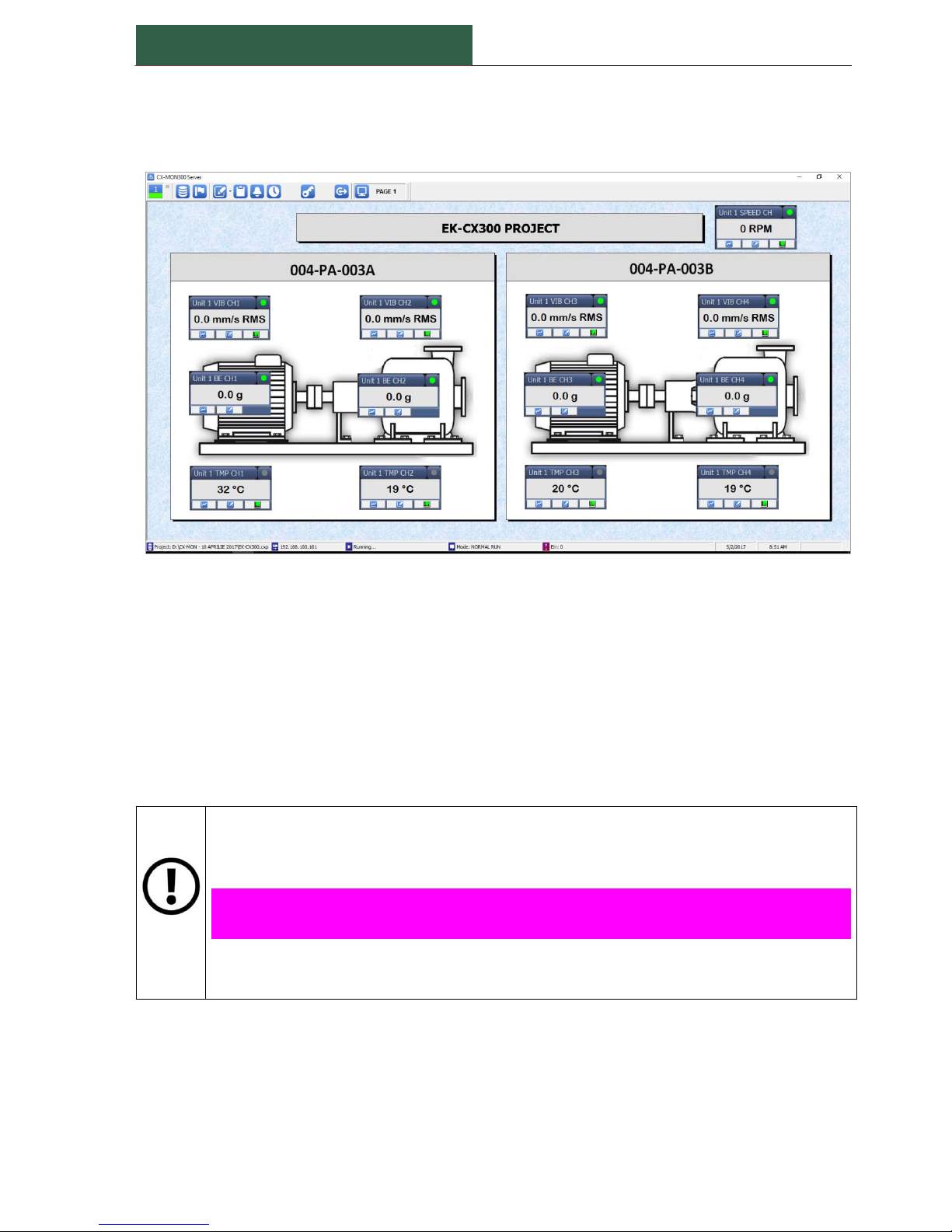
CX-MON300 Software is able to manage the measurements from up to 10 CX300 units. The
software is similar with a SCADA system and can be configured by the user.
Scheduled, On Alarm or On demand the measurements (including spectra) can be transferred to
any CXSpectra© database.
For more details, see CX-MON300 User Manual.
CX-MON300Client is simple software being a client for the CX-MON300.
Many client installations are allowed.
Page 15
CX300 MODULE – User manual
Doc.2016002
-14-
This software is almost identically with the server application, but cannot visualize spectra and
time signals.
For more details, see CX-MON300Client User Manual.
Figure 3 - Showing the measurements in CX-MON300 software
6. DEVICE INSTALLATION
The unit has been designed and manufactured in a way assuring a high level of user safety and
resistance to interference occurring in a typical industrial environment. In order to take full
advantage of these characteristics installation of the unit must be conducted correctly and
according to the local regulations.
Read the basic safety requirements prior to starting the installation.
Ensure that the power supply voltage corresponds to the nominal voltage (18 to 36 V
DC).
ALL INSTALLATION WORKS MUST BE CONDUCTED WITH A DISCONNECTED
POWER SUPPLY!!!
Protecting the power supply connections against unauthorized persons must be taken
into consideration.
Page 16
Doc.2016002
CX300 MODULE – User manual
-15-
6.1. UNPACKING
After removing the unit from the protective packaging, check for transportation damage.
Figure 4 - CX300 enclosure dimensions (in mm)
Any transportation damage must be immediately reported to the carrier. Also, write down the unit
serial number located on the housing and report the damage to the manufacturer.
Page 17
CX300 MODULE – User manual
Doc.2016002
-16-
6.2. ASSEMBLY
The unit is designed for mounting inside housings (control panel, switchboard) insuring
appropriate protection against surges and interference. Metal housings must be
connected to ground in a way that complies with the governing regulations.
DISCONNECT THE POWER SUPPLY PRIOR TO STARTING ASSEMBLY.
Check the connections are wired correctly, prior to switching the unit on.
Caution
Installation should be conducted by qualified personnel. During installation, all
available safety requirements should be considered. The fitter is responsible for
executing the installation according to this manual, local safety and EMC regulations.
The unit is not equipped with an internal fuse or power supply circuit breaker.
Because of this, an external time-delay cutout fuse with a small nominal current value
must be used (recommended bipolar, max. 2A).
The diameter of power supply network cable must be selected somehow that in the
case of a short circuit of the cable from the side of the unit, the cable shall be
protected against destruction with an electrical installation fuse.
Wiring must meet the appropriate standards and local regulations and laws.
In order to secure against accidental short circuit, the connection cables must be
terminated with the appropriate insulated cable tips.
Tighten the clamping screws. The recommended tightening torque is 0.5 Nm.
Loose screws can cause fire or defective operation. Over tightening can lead to
damaging the connections inside the units and breaking the thread.
Unused terminals must not be used for connecting any connecting cables (e.g. as
bridges), because this can cause damage to the equipment or electric shock.
When the installation is completed, do not touch the unit’s connections when it is
switched on, because it carries the risk of electrical shock.
Due to possible significant interference in industrial installations, appropriate measures assuring
correct operation of the unit must be applied. To avoid the unit of improper indications keep
recommendations listed below.
Avoid running signal cables and transmission cables together with power supply cables and cables
controlling inductive loads (e.g. contactors). Such cables should cross at a right angle.
Contactor coils and inductive loads should be equipped with interference protection
systems, e.g. RC-type.
Use of screened signal cables is recommended. Signal cable screens should be connected to
the earth only at one of the ends of the screened cable.
In the case of magnetically induced interference, the use of twisted pair signal cables is
recommended. Twisted pair (best if shielded) must be used with 4 to 20 mA analogical
outputs.
Page 18
Doc.2016002
CX300 MODULE – User manual
-17-
In the case of measurement or control, signals are longer than 30m or go outside of the
building then additional safety circuits are required.
In the case of interference from the power supply side, the use of appropriate interference
filters is recommended. Bear in mind that the connection between the filter and the unit
should be as short as possible and the metal housing of the filter must be connected to the
earth with the largest possible surface. The cables connected to the filter output must not be
run with cables with interference (e.g. circuits controlling relays or contactors).
Connections of power supply voltage and measurement signals are executed using the screw
connections of the unit’s enclosure.
6.3. CONNECTION TERMINALS
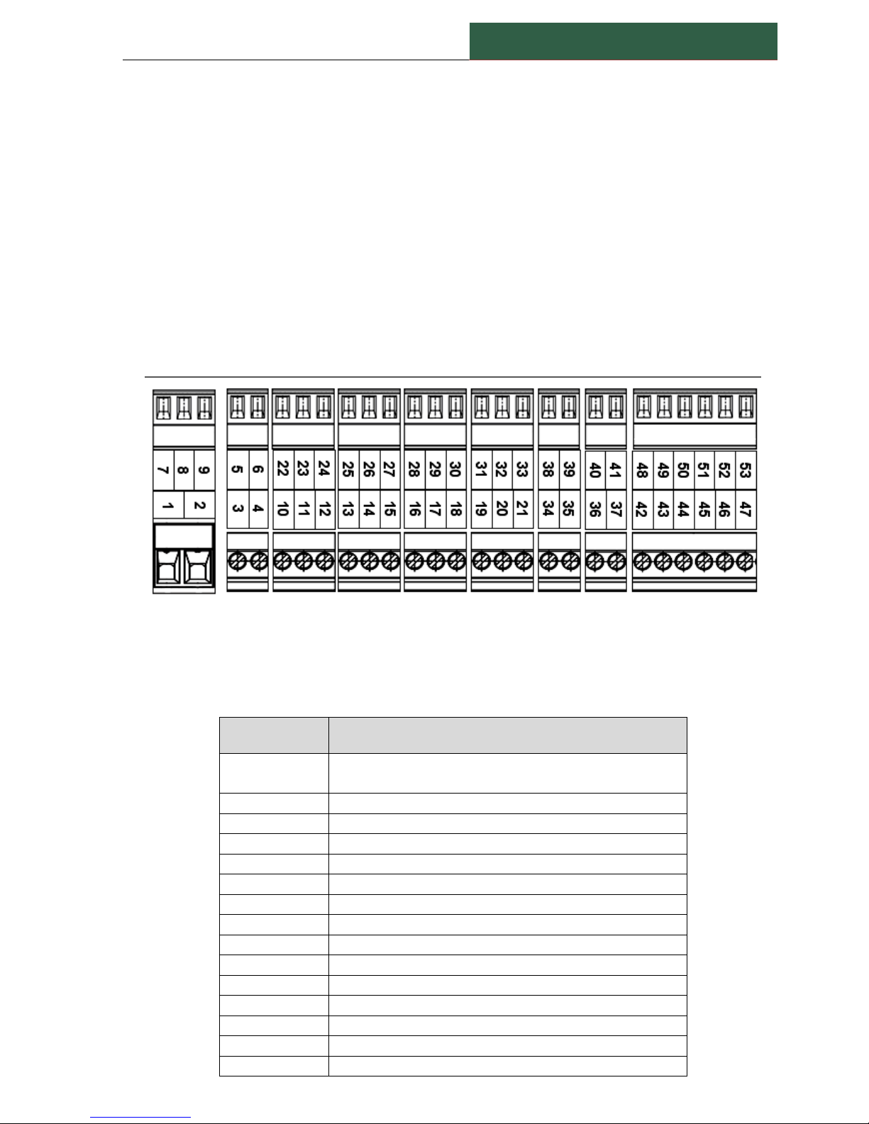
Each terminal is labeled with a number.
The actual meaning of each terminal is labeled inside on the terminals cover.
Figure 5 - Connection terminals
The table below shows the standard terminal assignment of the CX300 unit.
Table 2 - Terminal assignment
Terminal label
Description
1
Power supply - Positive side
Typically 24 V dc (18 to 36 V dc)
2
Power supply - Negative side
3
DI1 - Digital input (IN) - See Note 1
4
DI1 - Digital input (GND)
5
DI2 - Digital input (IN) - See Note 1
6
DI2 - Digital input (GND)
7
Speed CH1 (IN)
8
Speed CH1 (COM)
9
Speed CH1 power supply (12 or 24 V dc) - See Note 2
10
VIB CH1 - IN
11
VIB CH1 - COM
12
VIB CH1 - SCREEN - See Note 3
13
VIB CH2 - IN
14
VIB CH2 - COM
15
VIB CH2 - SCREEN - See Note 3
Page 19
CX300 MODULE – User manual
Doc.2016002
-18-
16
VIB CH3 - IN
17
VIB CH3 - COM
18
VIB CH3 - SCREEN - See Note 3
19
VIB CH4 - IN
20
VIB CH4 - COM
21
VIB CH4 - SCREEN - See Note 3
22
RTD CH1 - A
23
RTD CH1 - B
24
RTD CH1 - b - See Note 4
25
RTD CH2 - A
26
RTD CH2 - B
27
RTD CH2 - b - See Note 4
28
RTD CH3 - A
29
RTD CH3 - B
30
RTD CH3 - b - See Note 4
31
RTD CH4 - A
32
RTD CH4 - B
33
RTD CH4 - b - See Note 4
34
OUT1 (mA) - positive
35
OUT1 (mA) - negative - See Note 5
36
OUT2 (mA) - positive
37
OUT2 (mA) - negative - See Note 5
38
OUT3 (mA) - positive
39
OUT3 (mA) - negative - See Note 5
40
OUT4 (mA) - positive
41
OUT4 (mA) - negative - See Note 5
42
RL1 - CC (Relay contact)
43
RL1 – NC (Relay contact)
44
RL1 – NO (Relay contact)
45
RL2 - CC (Relay contact)
46
RL2 – NC (Relay contact)
47
RL2 – NO (Relay contact)
48
RL3 - CC (Relay contact)
49
RL3 – NC (Relay contact)
50
RL3 – NO (Relay contact)
51
RL4 - CC (Relay contact)
52
RL4 – NC (Relay contact)
53
RL4 – NO (Relay contact)
54
LCD power supply + (Not accessible for the user)
55
LCD power supply - (Not accessible for the user)
56
LCD TX (Not accessible for the user)
57
LCD COM (Not accessible for the user)
58
LCD RX (Not accessible for the user)
59
Fan power supply (+24V) - See Note 6
60
Fan power supply (-24V)
NOTE 1: Logical "1" - short between IN and GND
Logical"0" - leave open
Page 20
Doc.2016002
CX300 MODULE – User manual
-19-
Do not apply any external voltage on these inputs!
A free relay contact or push-button must be used to activate the digital input.
NOTE 2: External speed sensor can be supplied at 12 or 24 V dc (max 100mA). The unit cover must
be removed, to have access to a jumper. The jumper position must be changed (for detail see
Chapter 7).
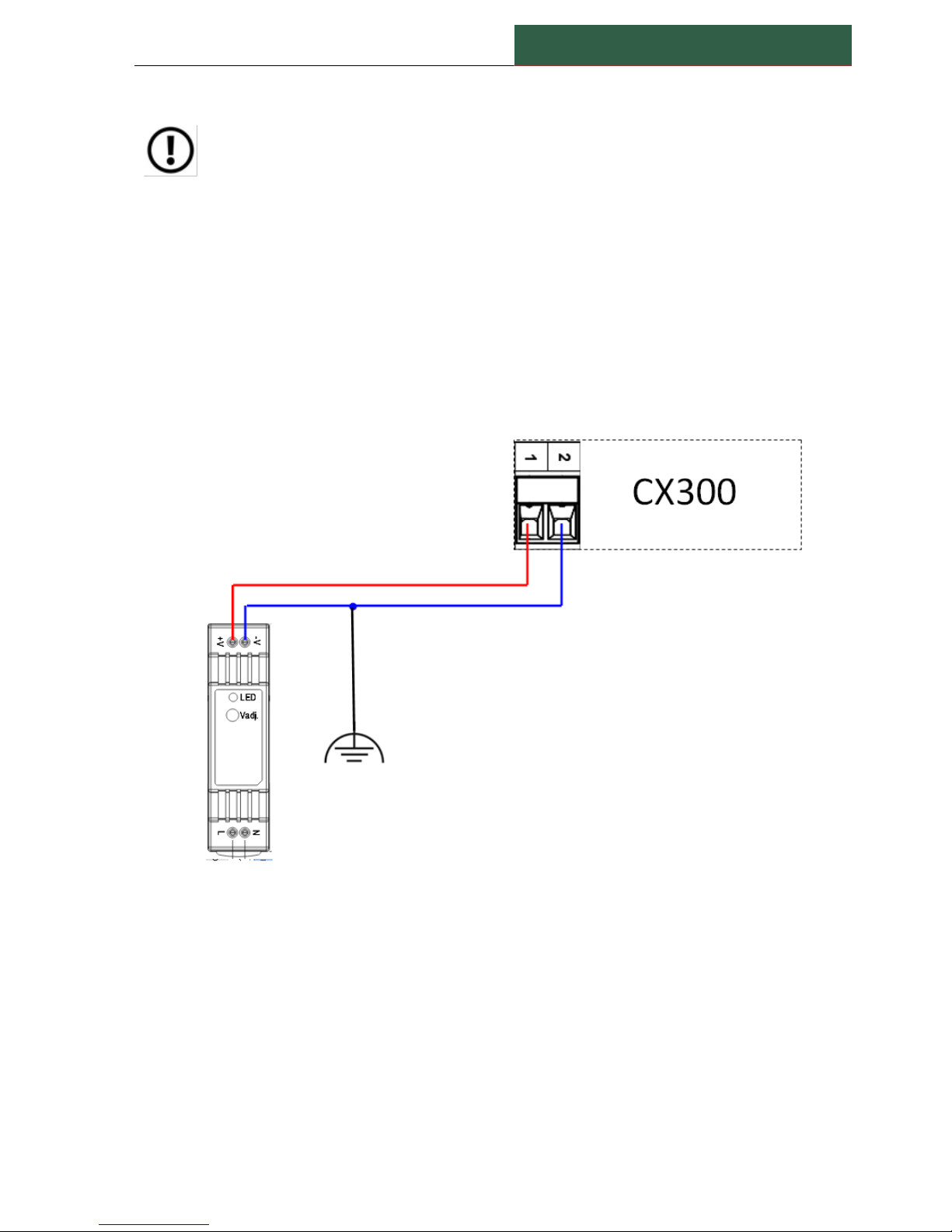
NOTE 3: These terminals are internally connected to the negative side of the power supply (24 V
dc). Because the power supply negative side is normally connected to an earth (shield) point,
these terminal can be also be considered a ground terminals. Signal cable screens should be
connected to the earth only at one of the ends of the screened cable. Leave unconnected if the
vibration screen is connected to the earth in another place.
Figure 6 -
Typical external power supply wiring diagram.
NOTE 4: These inputs are used for temperature measurement using RTD type temperature sensors
(by 2- and 3-wire method). Only RTD's type PT100 can be used. In 2-wire method, connect
terminal "B" with "b.”
NOTE 5: These outputs have a common minus (-) terminal. Therefore, the terminals 35, 37, 39 and
41 are connected together.
NOTE 6: The power supply for an additional cooling fan is the unit main power (Terminals 1 and 2).
A thermal switch placed inside of the unit supplies the external fan when the inside temperature
increases more than 60ºC.
The unit cover must be removed to have access to these terminals.
Page 21
CX300 MODULE – User manual
Doc.2016002
-20-
7. HARDWARE CONFIGURATION
Before to use the unit, this must be hardware configured, to meet the requirements of your
application.
Two hardware configurations are available:
Power to accelerometer (Enable/Disable)
Set the voltage for the speed sensor supply.
The unit cover must be removed to ensure the access to the baseboard!
Changed should be conducted by qualified personnel.
7.1. ACCELEROMETER POWER
If standard accelerometers are used, these need a constant current power supply of 4 mA@24Vdc.
A mini - switch with four positions is placed on the baseboard.
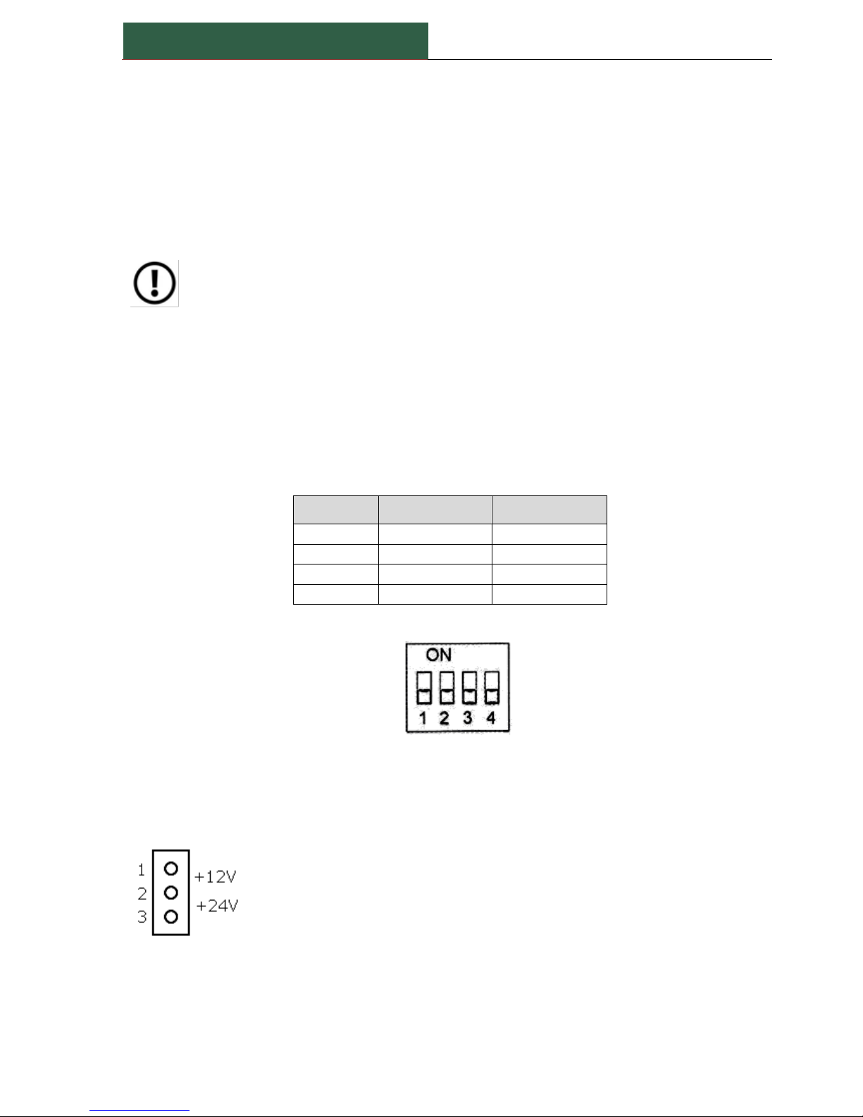
Change the position of the switches according to the next table:
Table 3
Switch No.
ON position
OFF position
1
Supply enabled
Supply disabled
2
Supply enabled
Supply disabled
3
Supply enabled
Supply disabled
4
Supply enabled
Supply disabled
Figure 7 - Power to accelerometers switches
Factory default for all switches is ON.
7.2. VOLTAGE FOR SPEED SENSOR
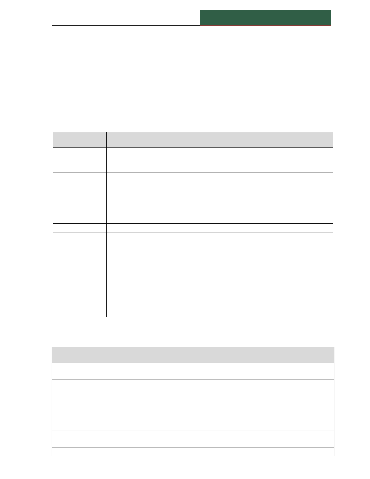
Place the jumper onto position 1-2 for +12V dc power supply.
Place the jumper onto position 2-3 for +24V dc power supply.
If power is not required, remove the jumper.
Figure 8 - Power to accelerometers switches
Page 22
Doc.2016002
CX300 MODULE – User manual
-21-
8. SOFTWARE CONFIGURATION
Each unit can be configured to meet the demands of customer application.
Software configuration will be done with an external PC application: CX300Config.
For more details, please read the CX300Config User Manual.
8.1. GENERAL UNIT CONFIGURATION
Table 4
Configuration
Description
Module Type
[READ-ONLY] Module type can be CX200 or CX300
Module code CX300 has a local LCD display, placed onto the front panel.
Module coded CX200 doesn’t have a display.
Module Name
Module name can be any text with max.17 letters.
Longer names will be truncated.
This is the 'friendly' module name.
Board Version
[READ-ONLY] This is a number to identify the module firmware version and the
specific hardware installed.
Serial Number
[READ-ONLY] This is the Module Serial Number
IP Address
This is the Module TCP/ IP Address
Max. Freq.
Range
This can be set to 3200 Hz or to 6400 Hz.
Will be the same for all vibration channels
Resolution
[READ ONLY] - Spectrum resolution - is the same for all vibration channels!
Relay settings
Relay can be set to be 'Fail-safe' - energized if is no alarm condition exists, or
'Normal' - energized on alarm
Start-up
multiplier
Alarms multiplier factor during start-up
Only for vibration and BE measurements.
Can be set from a list (X 1.5 up to X 10.0)
Start-up time
Start-up time [1 to 255 seconds]
The alarm multiplier is acting only in this time interval, after the starting-up.
8.2. VIBRATION AND BE MEASUREMENTS
Table 5
Configuration
Description
Transducer type
Transducer type to be connected (or set to NOT USED)
Selected from a list: Accelerometer, Velocity or Displacement
Sensitivity
Transducer sensitivity in 'mV/g', 'mV/mm/sec' or 'mV/um'
Show Unit
Show unit for this vibration measurement
Selection of: mm/s2, g, mm/sec, m/sec, in/sec, μm, mm, inch
Show Detection
RMS, Peak or P-P
Scale
Scale (in Show units) for this vibration measurement channel - This will be also
the scale for mA Output, if is enabled.
Transducer LO
Transducer lower bias voltage allowed. Min -24V
Used to check transducer integrity
Transducer HI
Transducer higher bias voltage allowed. Max.+24V
Page 23
CX300 MODULE – User manual
Doc.2016002
-22-
Spectrum LPF
Spectrum frequency range (in Hz)
Selected from a list: 200 Hz to 6400 Hz
Value cannot be more than Max. Freq. Range (See Table 4)
Use measured
speed
Enabled or disabled. If this is enabled, the speed value will be transferred in
CXSpectra© database, together with the total value, BE and spectrum
Total HPF
High Pass Filter for Total Value calculation (in Hz)
Selected from a list: (none), 5 Hz or 10 Hz
Total LPF
Low Pass Filter for Total Value calculation (in Hz)
Selected from a list: 200 Hz to 6400 Hz
This vale cannot be greater than SpectrumLPF
Alarm vibration
Enabled or disabled. Trigger measurement alarm condition.
Warning Vib
Warning level for vibration (in Show Unit)
Danger Vib
Danger level for vibration (in Show Unit)
Measure BE
Enable/Disable BE measurement for this channel
Alarm BE
Enabled or disabled. Trigger measurement alarm condition.
Warning BE
Warning level for BE (in "gBE")
Danger BE
Danger level for BE (in "gBE")
Delay RLY
Delay in Relay action (seconds)
Selected from a list: 1 to 10 seconds
Map Warning Vib
Map vibration Warning Alarm to a specific Relay
Selected from a list: (none), RLY1, RLY2, RLY3 or RLY4
Map Danger Vib
Map vibration Danger Alarm to a specific Relay
Selected from a list: (none), RLY1, RLY2, RLY3 or RLY4
Map Warning BE
Map BE Warning Alarm to a specific Relay
Selected from a list: (none), RLY1, RLY2, RLY3 or RLY4
Map Danger BE
Map BE Danger Alarm to a specific Relay
Selected from a list: (none), RLY1, RLY2, RLY3 or RLY4
mA Output
Enable/Disable current output (4 to 20 mA) for this measurement
8.3. TEMPERATURE MEASUREMENTS
Table 6
Configuration
Description
Show Unit
Temperature show unit, either ºC or ºF (or set to NOT CONNECTED)
Scale LO
Scale LO value, from selection: -50, -25, 0 (in Show Unit)
Scale HI
Scale HI value, from selection: 100, 125, 150, 200 or 300 (in Show Unit)
Alarm temperature
Enable/Disable temperature alarms.
Trigger measurement alarm condition.
Warning Temperature
Warning level for temperature (in Show Unit)
Danger Temperature
Danger level for temperature (in Show Unit)
Map Warning Temp
Map temperature Warning Alarm to a specific Relay
Selected from a list: (none), RLY1, RLY2, RLY3 or RLY4
Map Danger Temp
Map temperature Danger Alarm to a specific Relay
Selected from a list: (none), RLY1, RLY2, RLY3 or RLY4
Page 24
Doc.2016002
CX300 MODULE – User manual
-23-
8.4. SPEED MEASUREMENT
Table 7
Configuration
Description
Show Unit
Speed show unit. Can be: RPM or Hz
Scale
Scale value, from selection: 200 to 20000 (in Show Unit)
Alarm speed
Enable/Disable alarm.
Trigger measurement alarm condition.
Warning Speed
Warning level for speed (in Show Unit)
Danger Speed
Danger level for speed (in Show Unit)
Map Warning Speed
Map speed Warning Alarm to a specific Relay
Selected from a list: (none), RLY1, RLY2, RLY3 or RLY4
Map Danger Speed
Map speed Danger Alarm to a specific Relay
Selected from a list: (none), RLY1, RLY2, RLY3 or RLY4
Before doing any change, just make sure that the machine is not running!
The manufacturer is not responsible for any damages caused by improper
settings. Modification should be conducted by qualified personnel. During
setting modification, all the available safety requirements should be
considered.
NOTE: The four current outputs (4 to 20 mA) are available only for Total Vibration value. By
request, additional four current outputs can be equipped for Temperature measurements, but two
relays (RLY3 and RLY4) will be removed (only RLY1 and RLY2 will be available).
In the above configuration, a part of the terminals table (Table 2) must be changed as shown
below (Table 8):
Table 8 -Modified terminals assignment
Terminal label
Description
48
OUT5 (mA) - positive
49
OUT5/6 COM - negative
50
OUT6 (mA) - positive
51
OUT7 (mA) - positive
52
OUT7/8 COM - negative
53
OUT8 (mA) - positive
Page 25
CX300 MODULE – User manual
Doc.2016002
-24-
9. NORMAL STARTING SEQUENCE
Table 9 – LED’s status on startup
LED
~ 1sec
>1 sec
Green
ON
ON
Red
ON
OFF
Yellow
ON
BLINK (See Note below)
NOTE:
1. If CX-MON300 application is already started, the yellow LED will blink fast (90% ON and 10% OFF
for a period of 1 second)
2. If CX-MON300 application doesn’t run, the yellow LED will blink symmetrically and fast (50% ON
and 50% OFF, for a period of 1 second)
3. If CX300 Module didn’t succeed to connect itself to the Ethernet Network, the Yellow LED will
blink symmetrically slow (50% ON and 50% OFF, for a period of ~ 2 seconds). Check the network
integrity and RESET the module.
10. CX300 LED INDICATOR
Green LED
ON – Indicate that the main processor running OK
OFF – Indicate a +5V power supply failure or the main processor is defective
Red LED
OFF – This is the normal status after the starting sequence
ON – Vibration cannot be acquired (defective A/D converters or a fault onto the Vibration
Board)
BLINK – A malfunction of the Output Board (Temperature, current output or Relays).
Yellow LED
BLINK FAST symmetrically; Ethernet network is OK. CX300 awaiting connection;
BLINK FAST (80% ON and 10% OFF). A client (CX-MON300) is connected and communicates
with the module;
BLINK SLOW symmetrically. CX300 cannot make a connection to the existing Ethernet
Network. Try to RESET the module.
Page 26
Doc.2016002
CX300 MODULE – User manual
-25-
11. TROUBLESHOOTING
Table 10 – Troubleshooting solution
Symptom
Possible cause
Solution
A CX300 module
cannot be connected
to CX-MON300
software.
Wrong IP Address
Module IP Address is
unchecked in
CX-MON300 software
Hardware network
connection
Check the IP Address for both CX300 module
and software.
Check module status in the communication list.
Check cables, switches, or router.
NOTE: The module must be connected to the
network BEFORE being switched-on.
Try a module reset (this action won’t change
relay’s position).
Switch again off and on the module, (this action
may change temporary relay’s position!)
Touchscreen is
irresponsive and
seems to be “frozen”.
Unknown
Press the ON/ OFF button continuously, for
about 10 sec. The display will be shut-off. Press
again the same button to start the display. This
action won’t change relay’s position.
A vibration channel
shows “Transducer
failure”.
Wrong “Transducer LO”
or “Transducer HI”
settings
Defective transducer
Readjust the setting parameters (use
CX300Config).
Replace transducer.
A temperature channel
shows “Transducer
failure”.
Short-circuit of RTD wires
or interrupted cable;
Defective RTD transducer
Check cable connection.
Check RTD sensor.
Replace temperature sensor.
A new setting is not
reflected in CX300
module.
Changes are done only if
CX300 is hardware reset.
Reset the module.
12. MAINTENANCE
The unit does not have any internal replaceable or adjustable components available to the user.
Pay attention to the ambient temperature in the room where the unit is operating.
Excessively high temperatures cause faster ageing of the internal components and shorten the
fault-free time of the unit's operation.
When the unit gets dirt, do not clean with solvents. For cleaning, just use warm water with a small
amount of detergent or in the case of more significant contamination ethyl or isopropyl alcohol.
Page 27

CX300 MODULE – User manual
Doc.2016002
-26-
ADDENDUM A
Assigning Private Network IP Addresses to the CX300 Modules
Since not all CX300 modules have official Internet assigned addressees, there must be a specific
and accepted way to allocate addresses to those modules, without conflicting with anyone else's
Internet address.
RFC 1918 is the official document on which IP addresses are to be used in a non-connected or
"private" network. There are 3 blocks of numbers set aside specifically for this purpose.
Section 3: Private Address Space
The Internet Assigned Numbers Authority (IANA) has reserved the
following three blocks of the IP address space for private networks:
10.0.0.0 - 10.255.255.255
172.16.0.0 - 172.31.255.255
192.168.0.0 - 192.168.255.255
We will refer to the first block as "24-bit block", the second as "20-bit block", and the third as
"16-bit" block". Note that the first block is nothing but a single class A network number, while the
second block is a set of 16 continuous class B network numbers, and the third block is a set of 255
continuous class C network numbers.
For CX300 Modules use the 192.168.0.0 network with a 255.255.255.0 Class-C subnet mask. Any of
the above private networks are valid, but just be SURE to use the correct subnet-mask.
So, if you're using a Class-C network, you should number your TCP/IP enabled Modules as
192.168.1.2, 192.168.3, 192.168.1.4..., 192.168.1.255 and the PC running CX300-MON must have
any IP below these (Ex. 192.168.1.1 with 255.255.255.0 subnet-mask).
Page 28
Doc.2016002
CX300 MODULE – User manual
-27-
Documentation Feedback
Any suggestions and comments for improving this Application Notes should be e-mailed at
MaintTech Sweden uses feedback for continuous improvement of our documentation and for future
MaintTech products. We request comments be specific and include the product name and version. We
cannot provide personal responses to every message received, but please be assured that all feedback will
be given careful consideration for future improvements to the MaintTech documentation or software.
Technical Support
Contact Details
For any problem regarding this application, feel free to contact our support team at
To know more about us, visit the following website: http://www.mobilindustrial.ro/
 Loading...