

Page 1

able Of Contents
T
SUBJECT PAGE NO.
1.1 Maintenance Schedule . . . . . . . . . . . . . . . . . . . . . . . . . . . . . . . . . . . . . . . . . . 1-1
1.2 Side Views . . . . . . . . . . . . . . . . . . . . . . . . . . . . . . . . . . . . . . . . . . . . . . . . . . . . 1-5
NOTE
This section provides information unique to the FXDP police model motorcycle. Any information not presented in this supplement can be found in the Dyna Models Service Manual.
MAINTENANCE 1
Page 2

Page 3
HOME
4
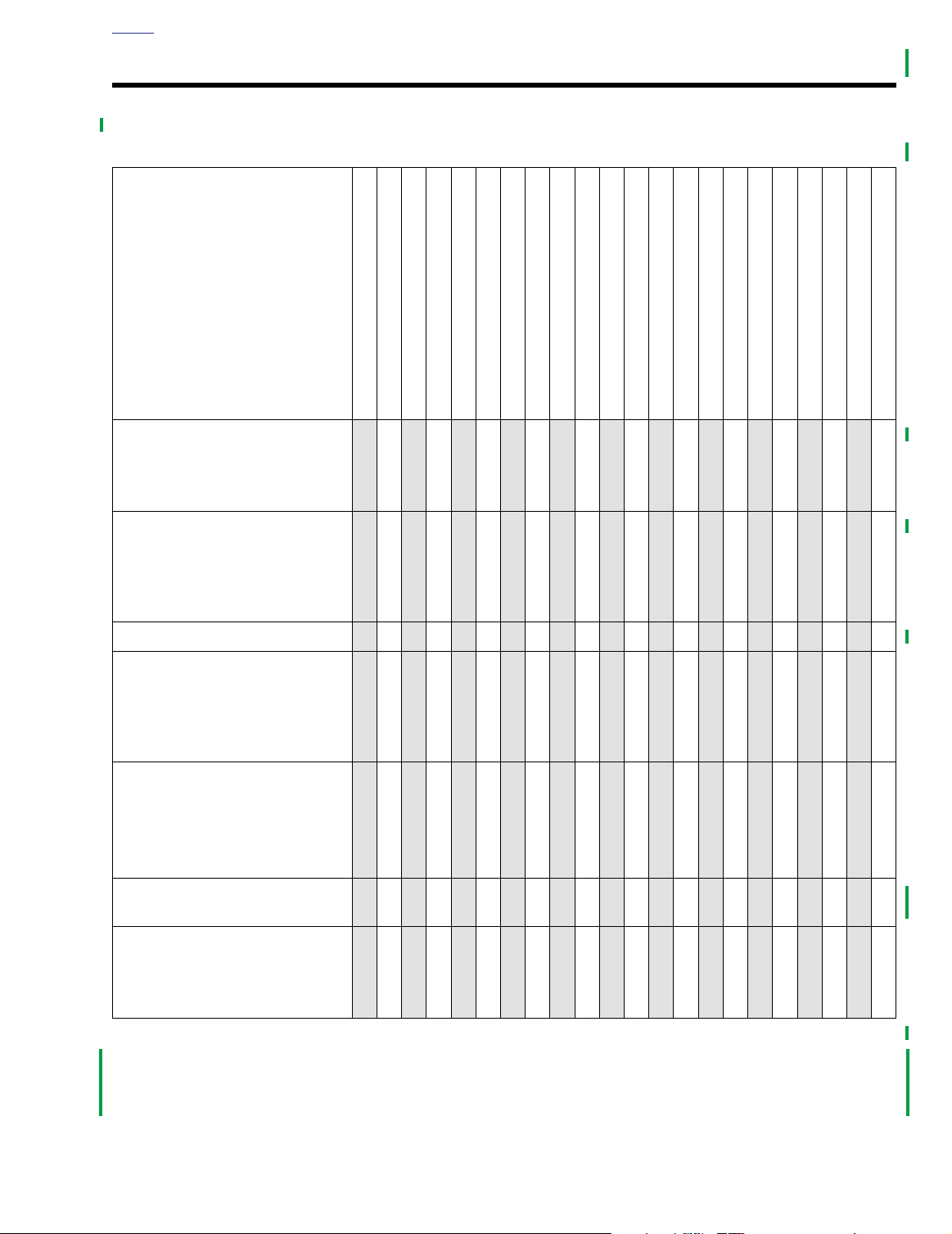
MAINTENANCE SCHEDULE 1.1
Table 1-1. Maintenance Schedule
1
1
1
1
2
2
2
2
3
3
3
3
4
4
4
4
5
7
0
5
0
0
0
0
0
M
M
I
I
I
7
8
6
0
0
0
0
0
0
0
K
K
M
M
MAINTENANCE TASK
AND SERVICE DATA
Engine oil (*)
Oil level:
Dipstick level depends on vehicle
temperature
Engine oil filter (*)
Filter tightening:
Hand tighten oil filter 1/2 to 3/4 turn
after gasket surface contacts filter
mounting surface.
1
2
5
7
0
2
5
7
0
2
5
7
0
2
5
7
0
5
0
5
0
5
0
5
0
5
0
5
0
5
0
0
0
0
0
0
0
0
0
0
0
0
0
0
0
0
0
0
0
0
0
0
M
M
M
M
M
M
M
M
I
I
I
I
I
I
P
R
1
E
R
D
E
4
6
0
0
0
I
0
0
K
K
M
M
IR
RRRRRRRRRRRRRRRRRRRR
R
RRRRRRRRRRRRRRRRRRRR
1
1
8
2
0
0
0
0
0
0
K
K
M
M
2
6
0
0
0
0
0
0
0
K
K
M
K
M
M
M
I
I
2
2
4
0
0
0
3
8
2
0
0
0
0
0
0
K
K
M
M
0
M
M
I
I
3
4
6
0
0
0
0
0
0
0
K
K
M
M
0
0
0
M
M
I
I
4
4
4
8
0
0
0
0
0
0
K
K
M
M
0
0
0
0
0
M
M
I
I
5
5
2
6
0
0
0
0
0
0
K
K
M
M
0
5
0
0
0
0
0
M
M
I
I
I
6
6
0
4
0
0
0
0
0
0
K
K
M
M
2
5
5
0
0
0
0
0
M
M
I
6
7
8
2
0
0
0
0
0
0
K
K
M
M
Battery (*)
Brake fluid level and condition
Brake fluid type:
D.O.T. 5 SILICONE BRAKE FLUID
Part No. 99902-77 (12 oz.) or
99901-77 (gallon)
Brake pads and discs for wear
Minimum pad thickness:
0.04 in. (1.02 mm)
II
Maximum brake disc lateral runout:
0.008 in. (0.2 mm)
Tire pressure and inspect tires for
wear/damage (*)
II
Primary chain adjustment
Deflection:
Cold: 5/8-7/8 in. (15.9-22.2 mm)
Hot: 3/8-5/8 in. (9.5-15.9 mm)
Tab le Code:
A
- Adjust.
I
- Inspect, and if necessary, correct, adjust, clean or replace.
L
- Lubricate with specified lubricant.
R
- Replace or change.
I
IIIIIIIIIIIIIIIIIIII
I
I
I I I I I I I I I I
IIIIIIIIIIIIIIIIIIII
IIIIIIIIIIIIIIIIIIII
I I I I I I I I I I
T
- Tighten to proper torque.
X
-Perform.
D
- Disassemble, lubricate and inspect.
(*)- Also perform prior to storage or annually.
2003 Dyna Police: Maintenance 1-1
Page 4
HOME
MAINTENANCE TASK
AND SERVICE DATA
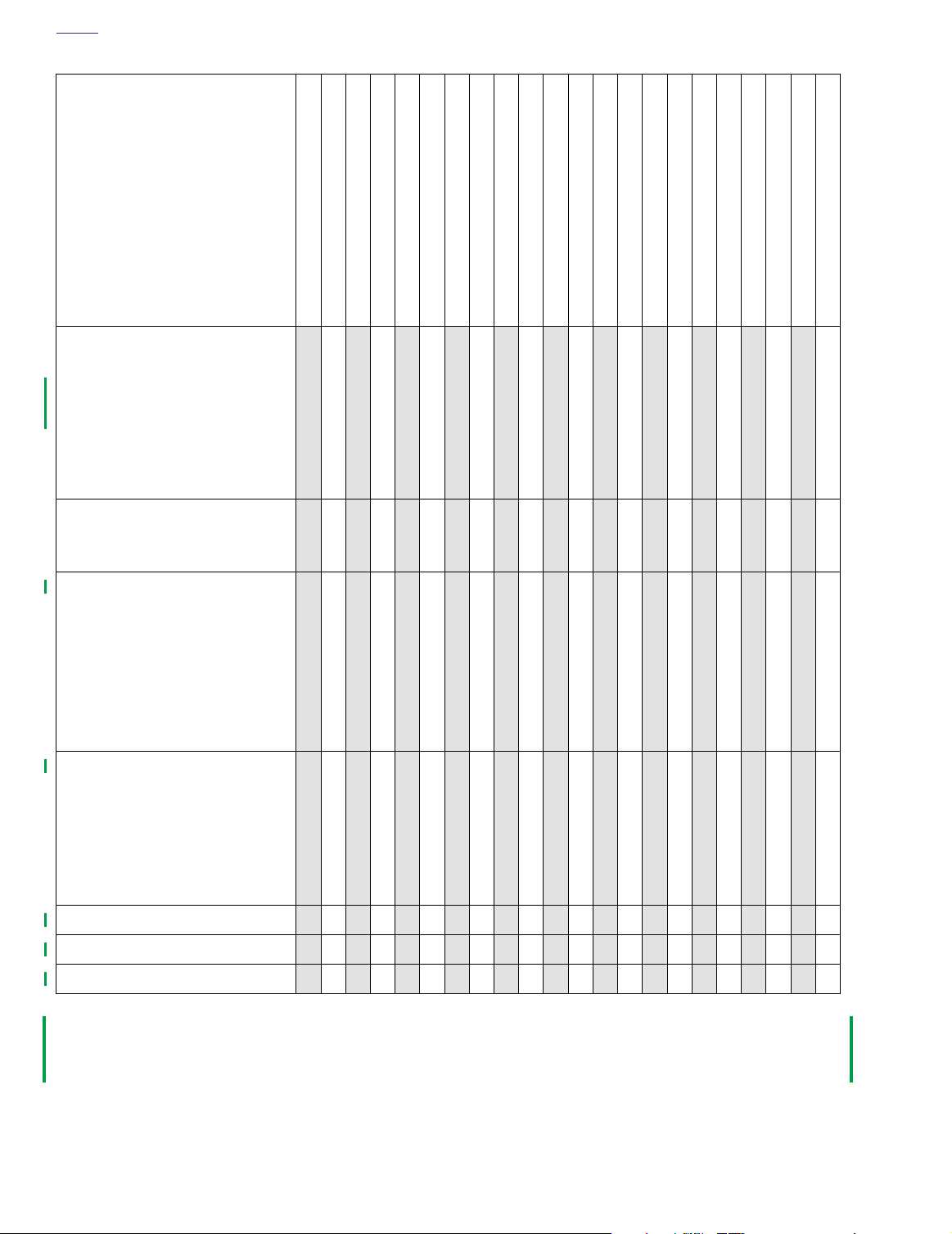
Primary chain lubricant
Lubricant level:
Visible between clutch and chaincase inner wall with vehicle upright,
26 oz (768.8 ml).
Lubricant type:
Part No. 99887-84 (quart) or
99886-84 (gallon)
Table 1-1. Maintenance Schedule
1
1
1
1
2
2
1
2
5
7
0
2
5
7
0
5
0
5
0
0
0
0
0
0
M
M
I
P
R
1
4
E
6
0
R
0
0
I
0
0
D
K
K
E
M
M
R
RRRRRRRRRRRRRRRRRRRR
0
0
0
M
M
I
I
1
8
2
0
0
0
0
0
0
K
K
M
M
5
0
0
0
0
M
M
I
M
I
I
1
2
6
0
0
0
0
0
0
0
K
K
K
M
M
M
0
0
5
0
0
0
0
0
0
0
M
M
I
I
2
2
3
4
8
2
0
0
0
0
0
0
0
0
0
K
K
M
M
2
2
5
5
0
0
0
0
0
M
M
I
I
I
3
4
6
0
0
0
0
0
0
0
K
K
M
M
2
3
3
3
3
4
4
4
4
7
0
2
5
7
0
2
5
0
5
0
5
0
0
0
M
4
4
0
0
0
K
M
0
0
0
M
M
I
K
M
M
I
I
4
5
8
2
0
0
0
0
0
0
K
K
M
M
0
0
0
0
0
0
0
M
M
I
I
5
6
6
6
0
4
0
0
0
0
0
0
0
0
0
K
K
M
M
5
5
0
0
0
0
0
M
M
I
I
6
7
8
2
0
0
0
0
0
0
K
K
M
M
5
7
0
5
0
0
0
0
0
M
M
I
I
I
7
8
6
0
0
0
0
0
0
0
K
K
M
M
Clutch adjustment
Hand lever free play:
1/16-1/8 in. (1.6-3.2 mm)
Transmission lubricant (*)
Lubricant level:
Bottom edge of FULL mark on dipstick with vehicle upright.
Lubricant type:
Part No. 99892-84 (quart)
Drain plug:
14-21 ft-lbs (19.0-28.5 Nm)
Rear belt deflection inspection (*)
Deflection:
5/16-3/8 in. (7.9-9.5 mm)
Bottom strand with 10 lb. (4.5kg)
upward force.
Specialty tool:
Part No. HD-35381
Rear belt and sprocket (*)
Steering head bearing
Front fork oil
X
R
II
I
A
X X X X X X X X X X
IRIRIRIRIRIRIRIRIRIR
IIIIIIIIIIIIIIIIIIII
I I I I I I I I I I
A A D A A
R
R
Tab le Code:
A
- Adjust.
I
- Inspect, and if necessary, correct, adjust, clean or replace.
L
- Lubricate with specified lubricant.
R
- Replace or change.
1-2 2003 Dyna Police: Maintenance
T
- Tighten to proper torque.
X
-Perform.
D
- Disassemble, lubricate and inspect.
(*)- Also perform prior to storage or annually.
Page 5
HOME
MAINTENANCE TASK
AND SERVICE DATA
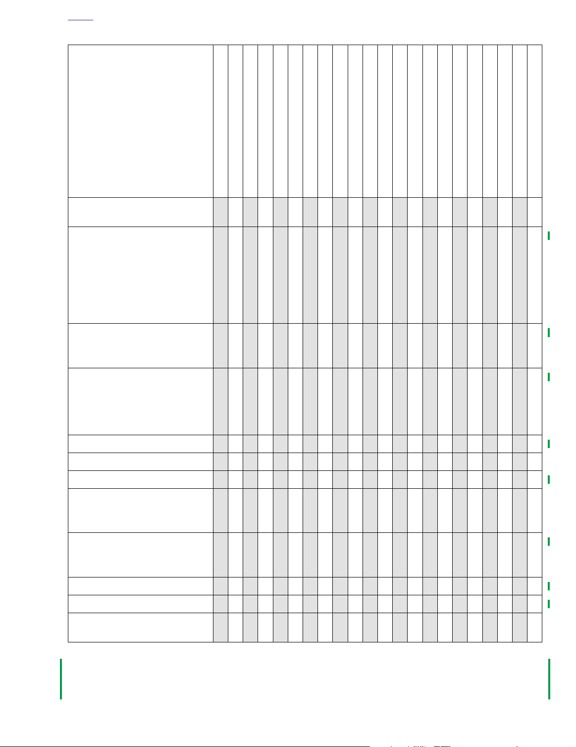
Table 1-1. Maintenance Schedule
1
1
1
1
2
2
1
2
5
7
0
2
5
7
0
5
0
5
0
5
0
0
0
0
0
0
M
P
R
1
E
6
R
0
I
0
D
K
E
M
0
M
M
I
I
4
8
0
0
0
0
0
0
K
K
M
M
0
0
0
M
M
I
I
1
1
2
6
0
0
0
0
0
0
K
K
M
M
0
0
0
0
0
M
M
I
I
2
2
0
4
0
0
0
0
0
0
K
K
M
M
0
5
0
0
0
0
0
M
M
I
I
2
3
8
2
0
0
0
0
0
0
K
K
M
M
2
2
5
5
0
0
0
0
0
M
M
I
I
I
3
4
6
0
0
0
0
0
0
0
K
K
M
M
2
3
3
3
3
4
4
4
4
7
0
2
5
7
0
2
5
0
5
0
5
0
0
0
0
0
M
M
I
4
4
4
8
0
0
0
0
0
0
K
K
M
M
0
0
0
M
M
I
I
5
5
2
6
0
0
0
0
0
0
K
K
M
M
0
0
0
0
0
M
M
I
I
6
6
0
4
0
0
0
0
0
0
K
K
M
M
5
5
0
0
0
0
0
M
M
I
I
6
7
8
2
0
0
0
0
0
0
K
K
M
M
5
7
0
5
0
0
0
0
0
M
M
I
I
I
7
8
6
0
0
0
0
0
0
0
K
K
M
M
Check air suspension - pressure,
operation and leakage
Spark plugs (*)
Plug type:
No. 6R12
Plug gap:
0.038-0.043 (0.97-1.09 mm)
Plug torque:
11-18 ft-lbs (14.9-24.4 Nm)
Air cleaner filter (*)
Cover screw torque:
36-60
in-lbs
(4.1-6.8 Nm)
Lubricate controls (*)
Front brake hand lever, clutch hand
lever, throttle control cables, clutch
control cable, rear brake pedal and
jiffy stand
Shift Lever
Operation of throttle controls
Enrichener operation
I
I
I
L
L
I
I
I I I I I I I I I I
I R I R I R I R I R
IIIIIIIIIIIIIIIIIIII
L L L L L L L L L L
L L L L L L L L L L
IIIIIIIIIIIIIIIIIIII
IIIIIIIIIIIIIIIIIIII
Engine idle speed
Idle speed:
950-1050 RPM
Fuel supply valve filter screen
Filter hex fitting torque:
15-20 ft-lbs (20.3-27.1 Nm)
Fuel system lines and fittings (*)
Repack rear fork bearings
Hinges, latches - saddlebags,
fuel door
Tab le Code:
A
- Adjust.
I
- Inspect, and if necessary, correct, adjust, clean or replace.
L
- Lubricate with specified lubricant.
R
- Replace or change.
I
I
L
I I I I I I I I I I
X
IIIIIIIIIIIIIIIIIIII
X
L L L L L L L L L L
T
- Tighten to proper torque.
X
-Perform.
D
- Disassemble, lubricate and inspect.
(*)- Also perform prior to storage or annually.
X
X
2003 Dyna Police: Maintenance 1-3
Page 6
HOME
MAINTENANCE TASK
AND SERVICE DATA
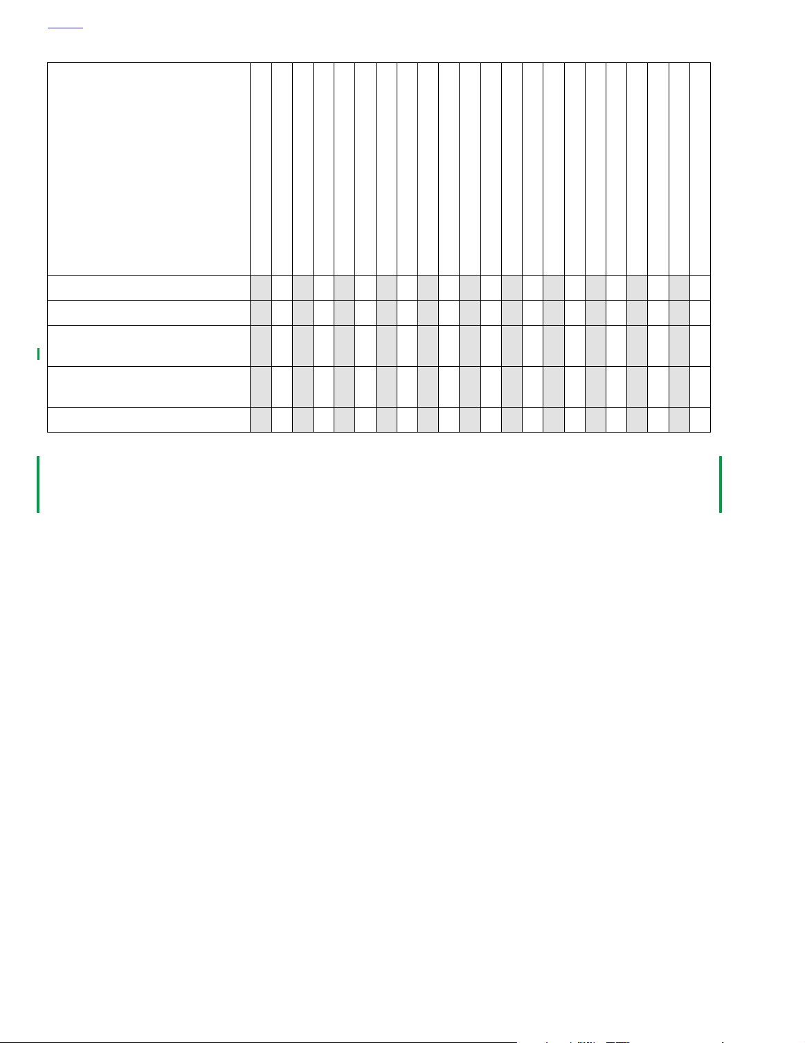
Check oil and brake lines for leaks
Table 1-1. Maintenance Schedule
1
1
1
1
2
2
1
2
5
7
0
2
5
7
0
5
0
5
0
0
0
0
0
0
M
M
I
P
R
1
4
E
6
0
R
0
0
I
0
0
D
K
K
E
M
M
I
0
0
0
M
M
I
I
1
8
2
0
0
0
0
0
0
K
K
M
M
IIIIIIIIIIIIIIIIIIII
5
0
0
0
0
M
M
I
M
I
I
1
2
6
0
0
0
0
0
0
0
K
K
K
M
M
M
0
0
5
0
0
0
0
0
0
0
M
M
I
I
2
2
3
4
8
2
0
0
0
0
0
0
0
0
0
K
K
M
M
2
2
5
5
0
0
0
0
0
M
M
I
I
I
3
4
6
0
0
0
0
0
0
0
K
K
M
M
2
3
3
3
3
4
4
4
4
7
0
2
5
7
0
2
5
0
5
0
5
0
0
0
M
4
4
0
0
0
K
M
0
0
0
M
M
I
K
M
M
I
I
4
5
8
2
0
0
0
0
0
0
K
K
M
M
0
0
0
0
0
0
0
M
M
I
I
5
6
6
6
0
4
0
0
0
0
0
0
0
0
0
K
K
M
M
5
5
0
0
0
0
0
M
M
I
I
6
7
8
2
0
0
0
0
0
0
K
K
M
M
5
7
0
5
0
0
0
0
0
M
M
I
I
I
7
8
6
0
0
0
0
0
0
0
K
K
M
M
Engine mounts
Operation of all electrical equipment and switches (*)
All critical fasteners except engine
head bolts
Road test
Tab le Code:
A
- Adjust.
I
- Inspect, and if necessary, correct, adjust, clean or replace.
L
- Lubricate with specified lubricant.
R
- Replace or change.
I
I
IIIIIIIIIIIIIIIIIIII
T
X
XXXXXXXXXXXXXXXXXXXX
T T T T T
I I I I
T
- Tighten to proper torque.
X
-Perform.
D
- Disassemble, lubricate and inspect.
(*)- Also perform prior to storage or annually.
1-4 2003 Dyna Police: Maintenance
Page 7
HOME
9845
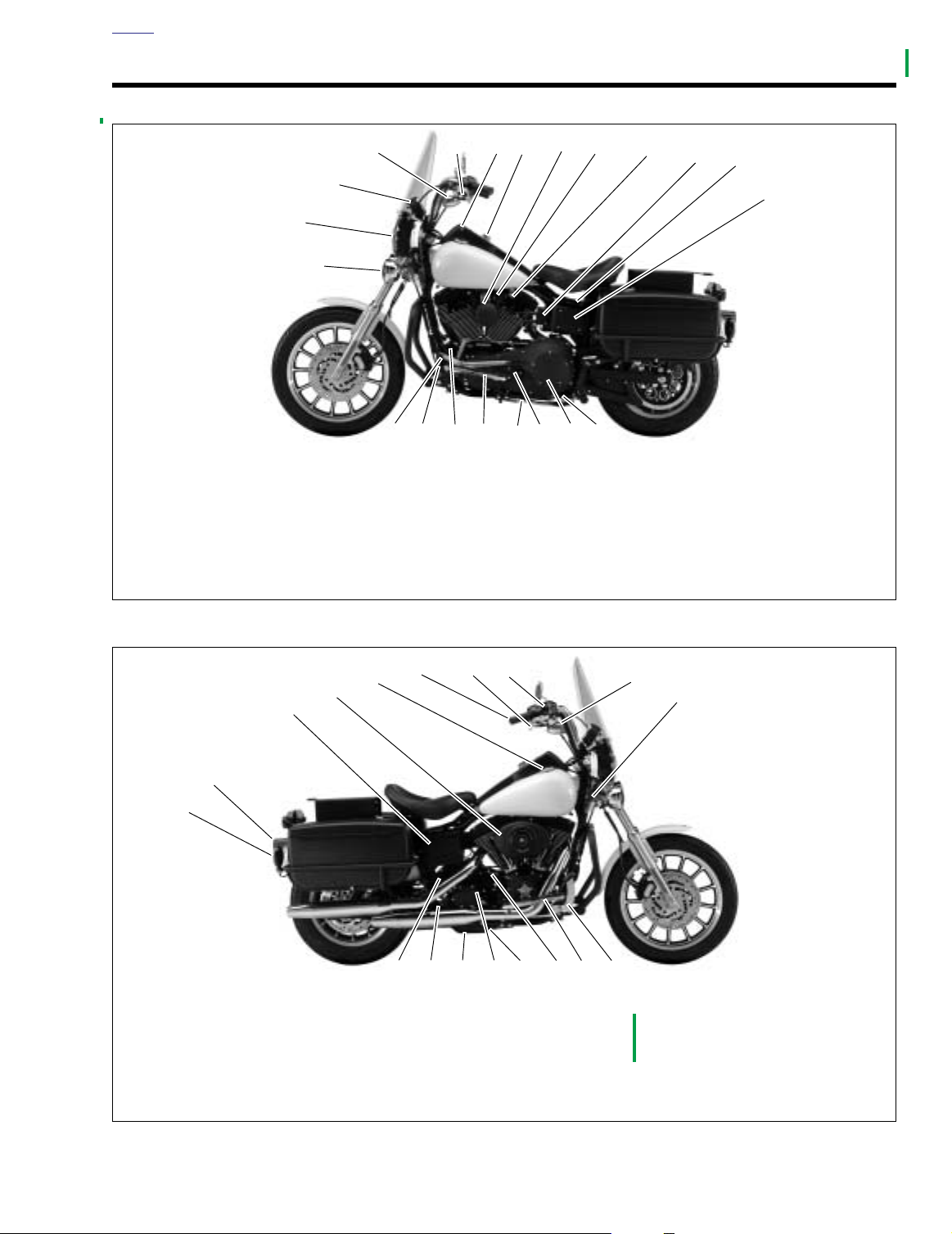
1. Rear turn signal lamp
2. Tail/stop lamp
3. Battery
4. Air cleaner
5. Fuel filler cap
6. Throttle control grip
7. Front brake hand lever
8. Front brake
master cylinder/reservoir
9. Front turn signal/running lamp
10. Fork Lock
11. Rear brake pedal
12. Footrest
13. Engine oil fill plug/dipstick
14. Engine oil pan drain
15. Transmission fill plug
16. Transmission drain plug
17. Rear brake
master cylinder/reservoir
18. Electric starter motor
10
11121314
15161718
7
9
6
5
4
3
2
1
8
SIDE VIEWS 1.2
9844
3
2
1
1. Pursuit lamp
2. Headlamp
3. Speedometer/tachometer
4. Front turn signal/running lamp
5. Clutch hand lever
6. Fuel gauge
7. Ignition/light key switch
8. Horn
17
76
16
4
21
9. Enrichener
10. Fuel supply valve
11. Ignition coil
12. Accessory connector
13. Main 30 amp circuit breaker,
5
20
(under seat)
system fuses/relays (under
electrical panel cover)
19
18
8
15
14
9
10
11
12
13
14. Primary drain plug
15. Clutch inspection cover
16. Primary chain inspection cover
17. Jiffy stand
18. Footrest
19. Engine oil filter
20. Voltage regulator
21. Gear shifter lever
Figure 1-1. FXDP (Left Side View)
Figure 1-2. FXDP (Right Side View)
2003 Dyna Police: Maintenance 1-5
Page 8

HOME
NOTES
1-6 2003 Dyna Police: Maintenance
Page 9

T
able Of Contents
CHASSIS 2
SUBJECT PAGE NO.
2.1 Specifications . . . . . . . . . . . . . . . . . . . . . . . . . . . . . . . . . . . . . . . . . . . . . . . . . . 2-1
2.2 Torque Values . . . . . . . . . . . . . . . . . . . . . . . . . . . . . . . . . . . . . . . . . . . . . . . . . 2-2
2.3 Vehicle Identification Number . . . . . . . . . . . . . . . . . . . . . . . . . . . . . . . . . . . . . 2-3
2.4 Seat . . . . . . . . . . . . . . . . . . . . . . . . . . . . . . . . . . . . . . . . . . . . . . . . . . . . . . . . . 2-4
2.5 Saddlebags . . . . . . . . . . . . . . . . . . . . . . . . . . . . . . . . . . . . . . . . . . . . . . . . . . . 2-6
2.6 Windshield . . . . . . . . . . . . . . . . . . . . . . . . . . . . . . . . . . . . . . . . . . . . . . . . . . . . 2-8
2.7 Pursuit Lamps . . . . . . . . . . . . . . . . . . . . . . . . . . . . . . . . . . . . . . . . . . . . . . . . . 2-10
2.8 Footboards . . . . . . . . . . . . . . . . . . . . . . . . . . . . . . . . . . . . . . . . . . . . . . . . . . . . 2-12
2.9 Radio Mounting Bracket . . . . . . . . . . . . . . . . . . . . . . . . . . . . . . . . . . . . . . . . . 2-14
NOTE
This section provides information unique to the FXDP police model motorcycle. Any information not presented in this supplement can be found in the Dyna Models Service Manual.
Page 10

Page 11
2
HOME
SPECIFICATIONS 2.1
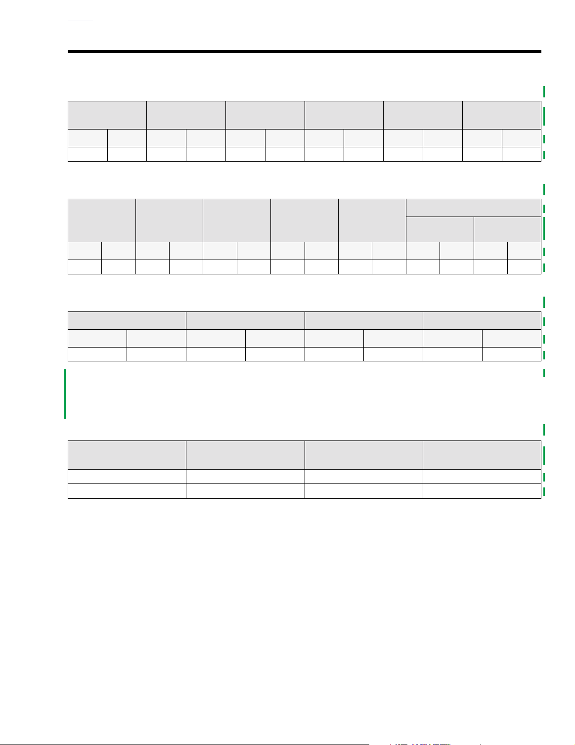
Table 2-1. Capacities
FUEL TANK
TOTAL
gal. liter gal. liter qt. liter oz. liter oz. liter oz. liter
5.2 19.68 1.1 4.16 3.0 2.84 24 0.71 26 0.77 11.5 0.34
FUEL TANK
RESERVE
OIL TANK
W/FILTER
TRANSMISSION
(APPROX.)
PRIMARY
CHAINCASE
FRONT
FORKS
Table 2-2. Dimensions
WHEELBASE
in. mm in. mm in. mm in. mm in. mm in. mm in. mm
63.5 1612.9 91.6 2326.6 33.5 850.9 5.5 139.7 47.5 1206.5 31.0 787.4 28.0 711.2
OVERALL
LENGTH
OVERALL
WIDTH
ROAD
CLEARANCE
OVERALL
HEIGHT
SADDLE HEIGHT
Solo Seat
Frame Mount
Seat
Table 2-3. Weight
DRY WEIGHT
lb. kg lb. kg lb. kg lb. kg
697.4 316.3 1200.0 544.3 460.0 208.6 740.0 335.7
NOTE
Gross vehicle weight rating (GVWR) (maximum allowable
loaded vehicle weight) and corresponding gross axle weight
rating (GAWR) are given on a label located on the frame
steering head.
GVWR GAWR FRONT GAWR REAR
Table 2-4. Tire Data
TIRE LOCATION SIZE
Front MT9019 Dunlop D402F PT 30 psi (206 kPa)
Rear MT90B16 Dunlop D402 PT 36 psi (248 kPa)
MANUFACTURER’S
DESIGNATION
TIRE PRESSURE (Cold)
2003 Dyna Police: Chassis 2-1
Page 12
HOME
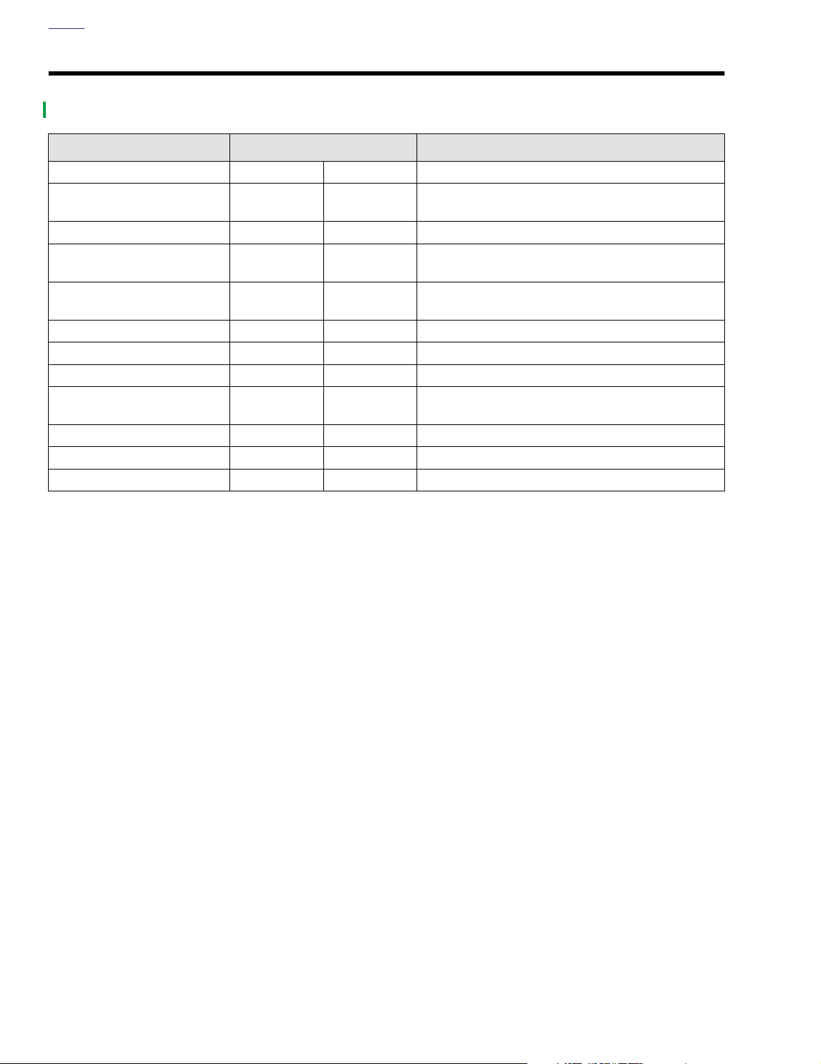
TORQUE VALUES 2.2
ITEM
Footboard mounting nuts 84-108
Footboard support mounting
bolts
Front seat mounting nut 120-216
Lower engine guard mounting
nuts
Pursuit lamp mounting bracket
screw
Radio mounting bracket screws 12-18 ft-lbs 16.3-24.4 Nm page 2-14
Rear seat mounting nuts 12-18 ft-lbs 16.3-24.4 Nm page 2-4
Saddlebag guard mounting nut 25-30 ft-lbs 33.9-40.7 Nm page 2-6
Saddlebag guard mounting
screw
Saddlebag mounting acorn nut 96-120
Shock mount stud nut 25-30 ft-lbs 33.9-40.7 Nm page 2-6
Tu rn signal mounting nut 12-15 ft-lbs 16.3-20.3 Nm page 2-6
25-35 ft-lbs 33.9-47.5 Nm page 2-12
18-22 ft-lbs 24.4-29.8 Nm page 2-12
30-35 ft-lbs 40.7-47.5 Nm page 2-10
12-18 ft-lbs 16.3-24.4 Nm page 2-6
TORQUE NOTES
in-lbs
in-lbs
in-lbs
9.5-12.2 Nm page 2-12
13.6-24.4 Nm page 2-4
10.8-13.6 Nm page 2-6
2-2 2003 Dyna Police: Chassis
Page 13

HOME
VEHICLE IDENTIFICATION NUMBER 2.3
GENERAL
See Figure 2-1. A 17-digit serial number, or Vehicle Identification Number (V.I.N.), is stamped on the top of the right front
frame downtube.
A label bearing the V.I.N. number is affixed to the right front
frame downtube.
Market Designation
Manufacturer and Make
Motorcycle Type
Model Designation
Engine
Harley-Davidson
V= Twin Cam 88TM (Carbureted)
An abbreviated V.I.N. is stamped on the left side crankcase at
the base of the cylinders.
NOTE
Always give the complete 17 digit V.I.N. when ordering parts
or making inquiries about your motorcycle.
1=Domestic
5=International
1=Heavyweight
GK = FXDP
Varies: 1-8
Model Year
K=Manufactured in Kansas City, MO
3=2003
Sequential Number
1HD1GK V 1* 3 K 100000
*Varies - can be 0-9 or X
Sample V.I.N. as it appears on the steering head - 1HD1GKV103K100000
Sample abbreviated V.I.N. as it appears on the left side crankcase - GKV3100000
Figure 2-1. Vehicle Identification Number (V.I.N.)
2003 Dyna Police: Chassis 2-3
Page 14

HOME
SEAT 2.4
REMOVAL
Solo Seat
1. See Figure 2-2. Remove screws (1), washers (2) and
nuts (5) from right and left side saddlebag guards.
2. Remove acorn nut (17) and washer (16).
3. Remove fuel tank screw (11) and washer (13) from rod
end (12), fuel tank mounting tabs, and frame backbone.
NOTE
If switching from solo seat to frame mounted seat, be sure to
remove seat cover (26).
Frame Mount Seat
1. See Figure 2-2. Remove screw (23) to detach seat from
fender.
2. Slide seat rearward to remove from frame.
INSTALLATION
Solo Seat
1. See Figure 2-2. Place rod ends (12) over rear fuel tank
mounting tabs.
2. Insert screw (11) with washer (13) through rod ends (12),
fuel tank mounting tabs, and frame backbone.
3. Loosely install acorn nut (17) and washer (16) on screw
(11).
4. Install screws (1), washers (2) and nuts (5) on right and
left side saddlebag guards. Tighten nuts to 12-18 ft-lbs
(16.3-24.4 Nm).
5. Tighten acorn nut (17) to 120-216
in-lbs
(13.6-24.4 Nm).
Frame Mount Seat
1. See Figure 2-2. Ver ify that seat bracket (24) is securely
fastened to bottom of seat. Position seat on frame with
bracket at rear.
2. Slide seat forward until tongue on front of seat bottom
engages bracket on frame.
3. Install screw (23) to fasten seat bracket to top of rear
fender. Tighten mounting bracket screw.
11WARNING1WARNING
After installing seat, pull upward on front of seat to be
sure it is locked in position. if seat is loose, it could shift
during vehicle operation and startle the rider, causing
loss of control and death or serious injury.
4. Pull up on seat to verify that it is locked in place.
2-4 2003 Dyna Police: Chassis
Page 15
HOME
p0080a2x
23
9
8
10
24
25
22
7
6
11
5
20
12
21
19
18
17
16
13
14
15
4
2
1
3
26
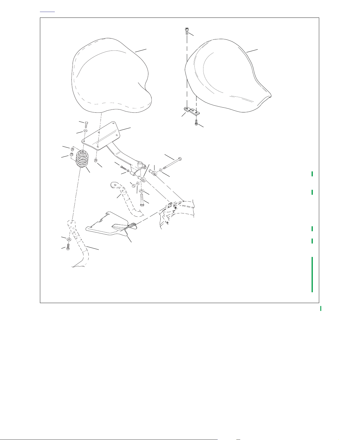
1. Screw (2)
2. Washer (2)
3. Right saddlebag guard
4. Spring (2)
5. Nut (2)
6. Nut (2) @12-18 ft-lbs (16.3-24.4 Nm)
7. Washer (2)
8. Screw (2)
9. Seat, solo
10. Seat support bracket
11. Fuel tank screw
12. Rod end (2)
13. Washer
14. Washer
15. Screw @ 18-22 ft-lbs (24.4-29.8 Nm)
16. Washer
17. Acorn nut @ 120-216 in-lbs (13.6-24.4 Nm)
18. Lockwasher (2)
19. Left saddlebag guard
20. Screw (2) @ 18-22 ft-lbs (24.4-29.8 Nm)
21. Nut (2) @ 96-120 in-lbs (10.8-13.6 Nm)
22. Seat, frame mount
23. Screw, frame mount
24. Bracket, seat - frame mount
25. Screw, frame mount (2)
26. Cover seat, plastic - spring mount
Figure 2-2. Seat
2003 Dyna Police: Chassis 2-5
Page 16

HOME
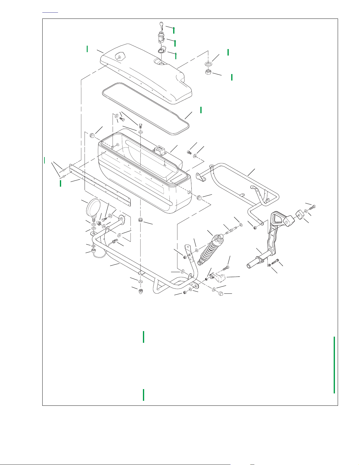
SADDLEBAGS 2.5
REMOVAL
1. See Figure 2-3. Remove acorn nuts (1) and washers (2)
from front, middle and rear of saddlebag (16).
2. Remove screws (15) and washers (14) from inside of
saddlebag. Note position of washers (7) between saddlebag and saddlebag guard (3, 17).
3. Remove saddlebag.
INSTALLATION
1. See Figure 2-3. Place saddlebag (16) into position inside
saddlebag guards (3, 17).
NOTE
In next step, be sure washers (7) are installed in between
saddlebag and saddlebag guard.
2. Insert screws (15) and washers (14) through saddlebag
grommets (8) and saddlebag guards.
3. Install acorn nuts (1) and washers (2) at front, middle
and rear of saddlebag (16). Tighten nuts to 96-120
(10.8-13.6 Nm).
in-lbs
SADDLEBAG GUARDS
Installation
1. See Figure 2-3. Place saddlebag mount into position on
shock mount stud (25).
2. Loosely install washer (11) screw (12), and saddlebag
mount to fender.
3. On left side, insert screw (18) and washer (19) thru left
saddlebag guard (17) and upright bracket (22). Install nut
(23) and tighten securely.
4. On right side, install washer (31) and nut (32) on screw
(27). Tighten to 25-30 ft-lbs (33.9-40.7 Nm).
5. Install nut (30) on shock mount stud (25). Tighten to 2530 ft-lbs (33.9-40.7 Nm).
6. Tighten screw (12) to 12-18 ft-lbs (16.3-24.4 Nm).
7. Install washer (10) and rubber washer (9) over threads
on turn signal (13).
8. Install turn signal thru mounting tab on saddlebag guard.
9. Install lockwasher (5) and nut (4) on turn signal. Tighten
nut to 12-15 ft-lbs (16.3-20.3 Nm).
10. Insert wire terminals into connector (6).
11. Connect turn signal connector.
12. Install pole lamp. See 8.5 POLE LAMP.
13. Install saddlebags (16).
14. Connect negative battery cable.
Removal
11WARNING1WARNING
To protect against shock and accidental start-up of vehicle, disconnect the negative battery cable before proceeding. Inadequate safety precautions could result in
death or serious injury.
1. Disconnect negative battery cable.
2. Remove saddlebag (16).
3. See 8.5 POLE LAMP. Remove pole lamp.
4. See Figure 2-3. Disconnect turn signal connector (6) [18,
19].
5. Remove wire terminals from turn signal connector.
6. Remove nut (4) and washer (5) from turn signal (13).
7. Remove turn signal (13), washer (10) and rubber washer
(9) from saddlebag guard (3, 17).
8. Remove nut (30) from shock mount stud (25).
9. On left side, remove screw (18) washer (19) and nut (23)
from upright bracket (22).
10. On right side, remove nut (32) and washer (31) from
screw (27).
11. Remove screw (12) and washer (11) from rear fender.
12. Remove saddlebag mount.
2-6 2003 Dyna Police: Chassis
Page 17
HOME
p0081a2x
35
39
38
13
1
10
9
5
4
1. Acorn nut (6)
2. Washer (6)
3. Right saddlebag guard
4. Nut (2)
5. Lockwasher (2)
6. Connector (2) [18, 19]
7. Washer (4)
8. Grommet (6)
9. Rubber washer (2)
10. Washer (2)
11. Washer (2)
12. Screw (2)
13. Turn signal (2)
14. Washer (6)
15. Screw (6)
42
41
40
36
37
16
34
15
14
15
8
14
17
8
12
18
11
24
2
7
8
25
26
23
19
33
29
6
3
2
1
16. Saddlebag (2)
17. Left saddlebag guard
18. Screw
19. Washer
20. Screw @ 25-30 ft-lbs
21. Washer
22. Upright bracket
23. Nut
24. Washer (2)
25. Shock mount stud (2)
26. Shock absorber (2)
27. Screw
28. Nut @ 25-30 ft-lbs
30
7
32
(33.9-40.7 Nm)
(33.9-40.7 Nm)
27
28
2
31
22
Motorcycle
frame
20
21
1
29. Washer (2)
30. Nut (2)
31. Washer
32. Nut
33. Spacer
34. Gasket (2)
35. Saddlebag lid (2)
36. Lockwasher, internal (2)
37. Nut (2)
38. Hinge (2)
39. Rivet, blind (32)
40. Tab pull, latch (2)
41. Lock mechanism
42. Key
Figure 2-3. Saddlebags and Saddlebag Guards
2003 Dyna Police: Chassis 2-7
Page 18
HOME
WINDSHIELD 2.6
REMOVAL
1. Cover the front fender with suitable material to protect
the fender paint.
2. See Figure 2-4. Loosen, but do not remove, four screws
(2) securing mounting brackets (1) to windshield clamps
(6).
3. Carefully pull windshield straight forward and up slightly,
so that mounting bracket slots (5) clear screws. Remove
windshield.
INSTALLATION
1. See Figure 2-4. Lower windshield into position, so that
right and left windshield brackets (1) are on the outboard
side of windshield clamps (6).
11WARNING1WARNING
Do not replace the screws and washers with ordinary
hardware. The screws and washers are designed to maintain a specific clamping force which other hardware does
not provide. Use of other hardware may allow the windshield to detach during riding, which can startle the rider
and cause loss of vehicle control, which could result in
death or serious injury.
2. Slide mounting brackets rearward so screws (2) on windshield clamps fit in slots in brackets. Make sure that
mounting bracket slots are positioned between flat washers (4) and windshield clamps.
NOTE
In the next step, position windshield so that it does not contact headlamp bracket, gauges, pursuit lamp brackets, handlebars, or any other part of vehicle.
3. Adjust windshield to desired angle and position. Using a
crosswise pattern, tighten all four mounting screws.
4. Turn the front forks to the full left and full right positions to
verify that movement is unrestricted.
8857
3
1
2
5
6
1. Windshield mounting bracket (2)
2. Screw (4)
3. Lockwasher (4)
4. Flat washer (4)
5. Adjustment slot
6. Windshield clamp (4)
Figure 2-4. FXDP Windshield Mounting Bracket
4
CARE
CAUTION
Do not clean Lexan® polycarbonate in hot sun or high
temperature. Powdered, abrasive or alkaline cleanser will
damage the windshield. Never scrape the windshield
with a razor blade or other sharp instruments because
permanent damage will result. Sunlight reflections off of
the inside curvature of a windshield can, at certain times
of the day, cause extreme heat build-up on motorcycle
instruments. Exercise care in parking. Park facing the
sun, place an opaque object over the instruments, or
adjust the windshield to avoid reflections. Harley-Davidson windshields are made of Lexan®, a more durable
and distortion-resistant material than other types of
motorcycle windshield material, But Lexan® still requires
attention and care to maintain.
Do not use liquid windshield “protectors” on your
●
windshield. Although they may work well on automobile safety glass, Harley-Davidson cannot ensure the
results when used on Lexan® Harley-Davidson windshields.
Do not use benzene, paint thinner, gasoline, or other
●
types of harsh cleaning agents on windshield. They
will damage the windshield surface.
Do not use benzene, paint thinner, gasoline, lubri-
●
cants or other cleaning agents on the rubber bushings. They will damage the bushing surfaces.
2-8 2003 Dyna Police: Chassis
Page 19
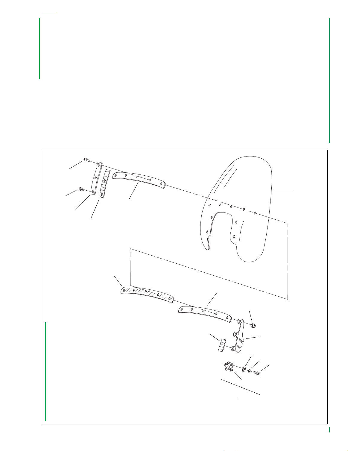
1. Shoulder screw (7)
2. Shoulder screw (2)
3. Vertical brace (2)
4. Cushion tape (vertical) (2)
5. Outer horizontal brace
6. Windshield
7. Cushion tape (inner horizontal)
8. Inner horizontal brace
9. Mounting bracket (2)
10. Cushion tape (cut to length)
11. Acorn nut (9)
12. Screw (4)
13. Lockwasher (4)
14. Flat washer (4)
15. Screw (4)
16. Windshield clamp (complete) (4)
1
2
3
4
5
6
7
8
9
10
11
12
15
16
13
14
p0114a2x
HOME
Notes
To remove minor surface scratches, use NOVUS® No. 2
●
SCRATCH REMOVER (Part No. 99836-94).
●
If you wish to use a windshield protectant on your windshield, use Harley® Glaze Polish and Sealant (Part No.
99701-84).
●
Covering the windshield with a clean, wet cloth for
approximately 15-20 minutes before washing will make
dried bug removal easier.
1. Use mild soap and warm water to wash the windshield.
2. Wipe dry with a soft, clean towel.
Figure 2-5. Windshield and Brackets
2003 Dyna Police: Chassis 2-9
Page 20
HOME
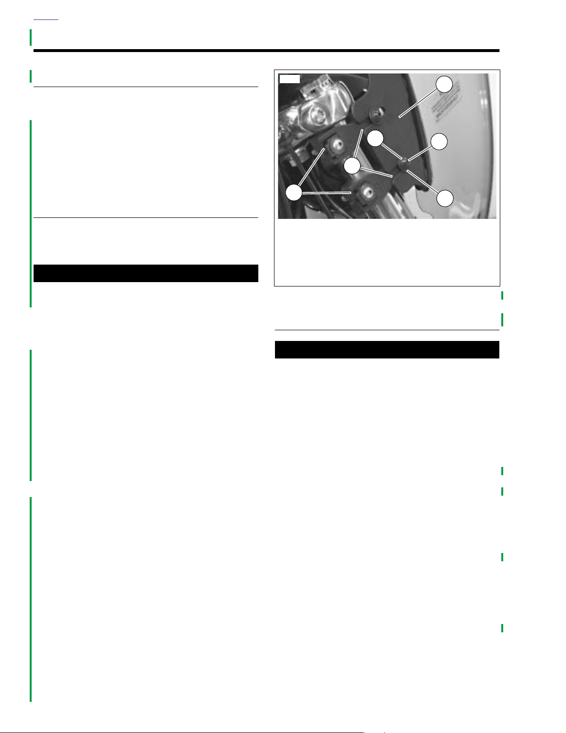
PURSUIT LAMPS 2.7
MOUNTING BRACKET REPLACEMENT
Removal
11WARNING1WARNING
To protect against shock and accidental start-up of vehicle, disconnect the negative battery cable before proceeding. Inadequate safety precautions could result in
death or serious injury.
1. Disconnect negative battery cable.
2. Remove fuel tank outer console assembly.
a. Remove the two screws securing the console above
the ignition switch.
b. Remove screw ahead of seat.
c. See Figure 2-6. Lift outer console assembly (1),
removing wiring harnesses (3) from slot (2) in front
of outer console.
3. See Figure 2-7. Disconnect pursuit lamp connector [73]
(5).
NOTE
Right pursuit lamp is connected to pin 1 of connector [73],
and left pursuit lamp is connected to pin 3.
4. Remove wire terminals from pursuit lamp connector shell
[73B] using appropriate pick tool (Snap-On TT600-3)
according to instructions in the AMP Multilock Electrical
Connector section of Appendix B in the Dyna Models
Service Manual.
5. Cut any cable straps holding pursuit lamp wiring harness
to vehicle, noting position(s) of cable strap(s) and wire
harness routing for replacement.
6. See Figure 2-8. Remove screw (7) and lamp mounting
bracket (8) with pursuit lamp assembly (1-6).
7. Repeat steps 5-6 for opposite side.
4. Install fuel tank outer console assembly.
a. See Figure 2-6. While lowering outer console
assembly (1) onto fuel tank console, push wiring
harnesses (3) into outer console slot (2).
b. Install the two screws above ignition switch and one
ahead of seat. Tighten screws securely.
5. Connect negative battery cable.
8855
3
1
1. Outer console assembly
2. Slot
3. Wiring harnesses
Figure 2-6. FXDP Console Wiring Harnesses
8856
2
1
2
3
4
Installation
1. See Figure 2-8. Mount pursuit lamp mounting bracket (8)
to lower triple clamp with screw (7). Tighten to 30-35 ftlbs (40.7-47.5 Nm). Repeat for opposite side.
2. See Figure 2-7. Route pursuit lamp wiring harnesses up
to fuel tank console. Install wire terminals into connector
[73] (5).
a. Install wire terminal from right pursuit lamp into pin 1
hole in connector shell.
b. Install wire terminal from left pursuit lamp into pin 3
hole in connector shell.
3. Connect pursuit lamp connector [73]. Secure cable with
cable straps.
2-10 2003 Dyna Police: Chassis
5
1. Right handlebar control connector [22]
2. Pursuit lamp flasher connector [69]
3. Left handlebar control connector [24]
4. Ignition switch connector [33]
5. Pursuit lamp connector [73]
Figure 2-7. FXDP Console Connectors
Page 21

HOME
11WARNING1WARNING
p0083b2x
10
7
8
1
2
5
1. Pursuit lamp shell
2. Mounting ring
3. Pursuit lamp bulb
(right side - blue, left side - red)
4. Bezel ring
5. Screw (2)
6. Nut (2)
7. Screw (2)
8. Lamp mounting bracket (2)
9. Nut (2)
10. Socket housing
Figure 2-8. FXDP Pursuit Lamp Assembly
HOUSING REPLACEMENT
To protect against shock and accidental start-up of vehicle, disconnect the negative battery cable before proceeding. Inadequate safety precautions could result in
death or serious injury.
1. Disconnect negative battery cable.
2. See Removal under 2.7 PURSUIT LAMPS, MOUNTING
BRACKET REPLACEMENT. Follow instructions and
remove pursuit lamp and mounting bracket.
9
3
4
6
3. See Figure 2-8. Remove nut (6), screw (5) and bezel ring
(4).
4. Loosen screws and disconnect two wire terminals from
back of pursuit lamp bulb (3).
5. Pull GY/BK wire through plastic conduit and pursuit lamp
housing (1).
6. Remove nut (9) securing pursuit lamp housing to mounting bracket (8).
7. Install new pursuit lamp housing onto mounting bracket
and secure with nut.
8. Temporarily mount pursuit lamp housing and mounting
bracket on lower triple clamp and check that housing
points straight ahead when vehicle is upright with front
fork pointing straight. If housing is not straight, loosen nut
and readjust housing, then retighten nut.
9. Push GY/BK wire through pursuit lamp housing, mounting bracket and plastic conduit.
10. See Installation under 2.7 PURSUIT LAMPS, MOUNT-
ING BRACKET REPLACEMENT. Follow instructions
and install pursuit lamp and mounting bracket.
11. Connect two wire terminals to pursuit lamp bulb.
12. Install pursuit lamp bulb in pursuit lamp housing. Make
certain to install mounting ring (2) between bulb and
housing. Install bezel ring. Secure with nut and screw.
13. Connect negative battery cable.
BULB REPLACEMENT
11WARNING1WARNING
To protect against shock and accidental start-up of vehicle, disconnect the negative battery cable before proceeding. Inadequate safety precautions could result in
death or serious injury.
1. Disconnect negative battery cable.
2. See Figure 2-8. Remove nut (6), screw (5) and bezel ring
(4).
3. Loosen screws and disconnect two wire terminals from
back of pursuit lamp bulb (3).
4. Connect two wire terminals to new pursuit lamp bulb.
5. Install pursuit lamp bulb in pursuit lamp housing (1).
Make certain to install mounting ring (2) between bulb
and housing. Install bezel ring. Secure with nut and
screw.
6. Connect negative battery cable.
2003 Dyna Police: Chassis 2-11
Page 22

HOME
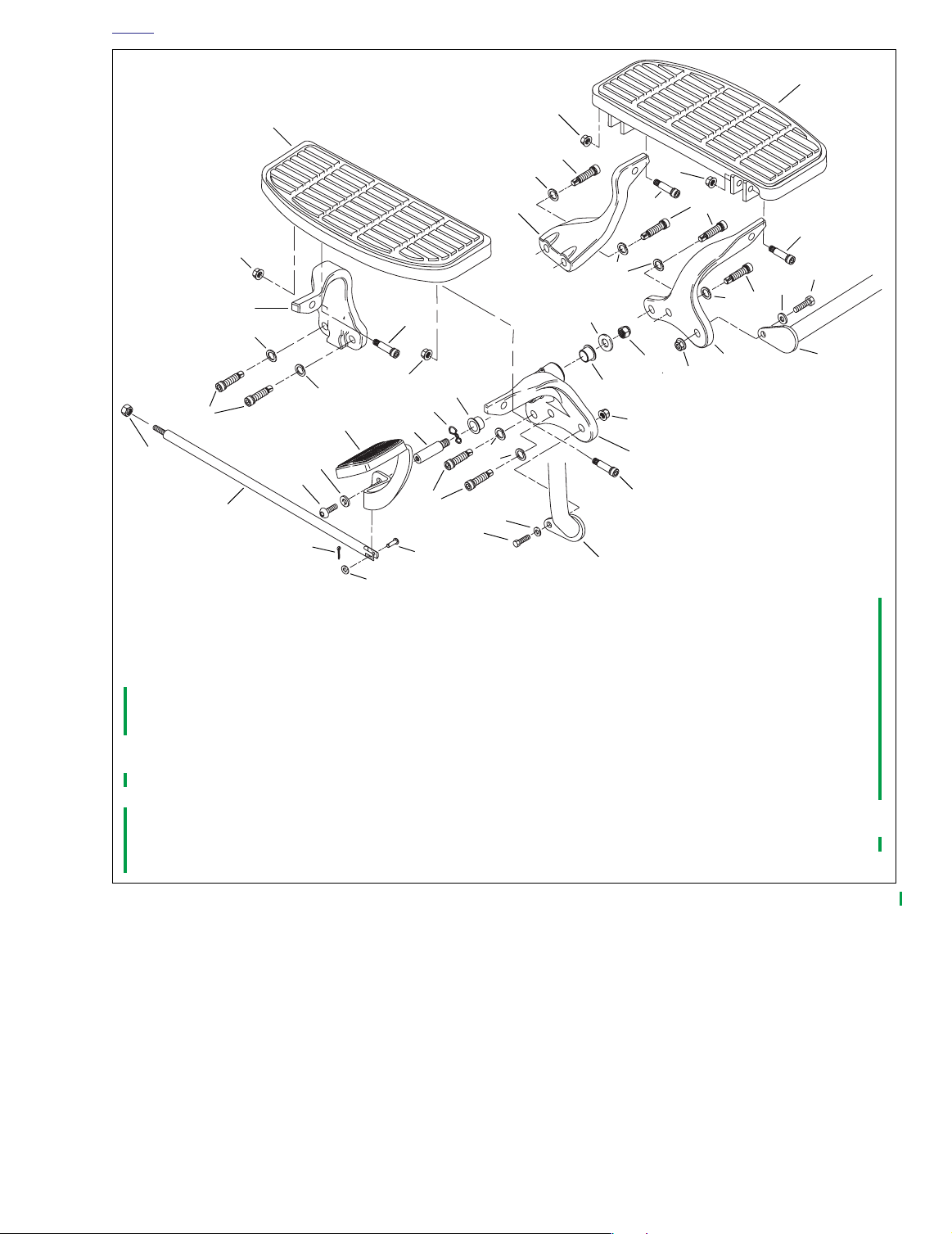
FOOTBOARDS 2.8
REMOVAL
Left Side, Footboard Only
1. See Figure 2-9. Remove two screws (8) and nuts (11)
securing footboard (14) to footboard support brackets
(13 and 18).
2. Remove footboard from brackets.
Right Side, Footboard Only
1. See Figure 2-9. Remove two screws (8) and nuts (11)
securing footboard (12) to footboard support brackets
(10 and 23).
2. Remove footboard from brackets.
Left Side Footboard Assembly
1. See Figure 2-9. Remove screw (15), washer (16) and nut
(19) securing left engine guard mount (17) to left front
footboard support (18).
2. Remove bolts (6) and lockwashers (7) securing left front
footboard support (18) and left rear footboard support
(13) to frame.
Right Side Footboard Assembly
1. See Figure 2-9. Remove cotter pin (3) and washer (2)
from clevis pin (1).
2. Remove clevis pin from push rod (5).
3. Remove screw (29), washer (30) and nut (31) securing
right engine guard mount (24) to right front footboard
support (23).
4. Remove bolts (6) and lockwashers (7) securing right
front footboard support (23) and right rear footboard support (10) to frame.
INSTALLATION
Left Side, Footboard Only
1. See Figure 2-9. Mount footboard (14) to footboard support brackets (13 and 18) with two screws (8) and nuts
(11).
2. Tighten nuts to 84-108 in-lbs (9.5-12.2 Nm).
Right Side, Footboard Only
1. See Figure 2-9. Mount footboard (12) to footboard support brackets (10 and 23) with two screws (8) and nuts
(11).
2. Tighten nuts to 84-108 in-lbs (9.5-12.2 Nm).
Left Side Footboard Assembly
1. See Figure 2-9. Secure left rear footboard support (13)
and left front footboard support (18) to frame.
a. Install bolts (6) and lockwashers (7).
b. Tighten bolts to 25-35 ft-lbs (33.9-47.5 Nm).
2. Secure left engine guard mount (17) to left front footboard support.
a. Install screw (15), washer (16), and nut (19).
b. Tighten nut to 18-22 ft-lbs (24.4-29.8 Nm).
Right Side Footboard Assembly
1. See Figure 2-9. Secure right rear footboard support (10)
and right front footboard support (23) to frame.
a. Install bolts (6) and lockwashers (7).
b. Tighten bolts to 25-35 ft-lbs (33.9-47.5 Nm).
2. Secure right engine guard mount (24) to right front footboard support (23).
a. Install screw (29), washer (30), and nut (31).
b. Tighten nut to 18-22 ft-lbs (24.4-29.8 Nm).
3. Install push rod (5) over mounting hole in brake pedal
(4).
4. Push clevis pin (1) through push rod and brake pedal.
5. Install washer (2) and cotter pin (3).
2-12 2003 Dyna Police: Chassis
Page 23
HOME
p0101a2x
14
12
11
10
7
7
6
9
4
27
28
5
3
2
1. Clevis pin
2. Washer
3. Cotter pin
4. Brake pedal
5. Push rod
6. Bolt (8) @ 25-35 ft-lbs (33.9-47.5 Nm)
7. Lockwasher (8)
8. Screw (4)
9. Nut
10. Right rear footboard support
11. Nut (4)@ 84-108 in-lbs (9.5-12.2 Nm)
12. Right footboard
13. Left rear footboard support
14. Left footboard
15. Screw
16. Washer
11
26
11
6
7
13
11
8
6
8
7
7
8
20
21
19
25
22
22
6
18
15
16
17
31
7
6
30
29
1
17. Left engine guard mount
18. Left front footboard support
19. Nut @ 18-22 ft-lbs (24.4-29.8 Nm)
20. Washer
21. Nut @ 30-35 ft-lbs (40.7-47.5 Nm)
22. Bushing
23. Right front footboard support
24. Right engine guard mount
25. Wave washer
26. Pivot shaft
27. Washer
28. Screw @ 30-35 ft-lbs (40-7-47.5 Nm)
29. Screw
30. Washer
31. Nut @ 18-22 ft-lbs (24.4-29.8 Nm)
23
8
24
Figure 2-9. Footboards
2003 Dyna Police: Chassis 2-13
Page 24

HOME
RADIO MOUNTING BRACKET 2.9
REMOVAL
1. Remove pole lamp. See 8.5 POLE LAMP.
2. See Figure 2-10. Remove screws (2), washers (3) and
nuts (4) securing radio mounting bracket (1) to fender.
INSTALLATION
1. Place radio mounting bracket (1) in place over fender
rails (5).
2. Install screws (2), washers (3) and nuts (4). Tighten
screws to 12-18 ft-lbs (16.3-24.4 Nm).
3. Install pole lamp. See 8.5 POLE LAMP.
p0102x2x
1
2
5
1. Radio mounting bracket
2. Screw @ 12-18 ft-lbs (16.3-24.4 Nm)
3. Washer
4. Nut
5. Fender rails
3
5
4
Figure 2-10. Radio Mounting Bracket
2-14 2003 Dyna Police: Chassis
Page 25

ENGINE 3
able Of Contents
T
NOTE
All service information in the Dyna Models Service Manual applies to the FXDP police model
motorcycle.
Page 26

Page 27

able Of Contents
T
FUEL SYSTEM 4
SUBJECT PAGE NO.
4.1 Fuel Tank . . . . . . . . . . . . . . . . . . . . . . . . . . . . . . . . . . . . . . . . . . . . . . . . . . . . . 4-1
NOTE
This section provides information unique to the FXDP police model motorcycles. Any information not presented in this supplement can be found in the Dyna Models Service Manual.
Page 28

Page 29

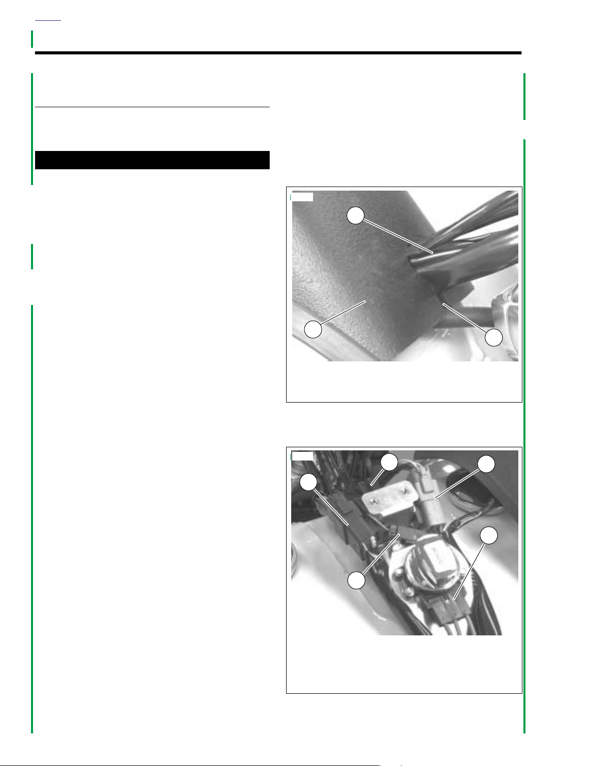
HOME
8856
1. Right handlebar control connector [22]
2. Pursuit lamp flasher connector [69]
3. Left handlebar control connector [24]
4. Ignition switch connector [33]
5. Pursuit lamp connector [73]
3
4
1
5
2
FUEL TANK 4.1
REMOVAL
1WARNING1WARNING
Gasoline is extremely flammable and highly explosive.
Always stop the engine when refueling or servicing the
fuel system. Do not smoke or allow open flame or sparks
near the work site. Inadequate safety precautions could
result in death or serious injury.
p0117x4x
4
1
2
NOTE
For instructions on properly draining fuel from the fuel supply
valve filter, refer to the Dyna Models Service Manual.
8. Drain fuel into adequately sized, approved gasoline container.
9. See Figure 4-3. Disconnect crossover hose (16) from
one end only.
10. Disconnect continuous venting vent line (17) from fitting
on fuel tank.
11. Remove front mounting bolt (14), acorn nut (32) and flat
washers (13).
12. Remove rear mounting bolt (11), acorn nut (32) and flat
washers (13).
NOTE
For instructions on properly disconnecting and connecting
the fuel gauge, see 8.15 FUEL GAUGE.
13. Disconnect fuel gauge connector [117] located under left
side of fuel tank (12).
14. Remove fuel tank from motorcycle.
H
a
3
1. Console outer assembly
2. Console
3. Fuel tank
4. Screw (3)
Figure 4-1. FXDP Console Assembly
1. If necessary, remove microphone from jack connection
on console.
2. See Figure 4-1. Remove console outer assembly (1).
a. Remove the two screws (4) on the console above
the ignition switch.
b. Remove screw (4) ahead of seat.
For instructions on properly removing and installing Deutsch
electrical connector wire terminals, refer to the Dyna Models
Service Manual.
3. See Figure 4-2. Disconnect wire harness connectors (1,
2, 3, 4 and 5).
4. Remove windshield. See 2.6 WINDSHIELD.
5. See Figure 4-3. Verify fuel supply valve (24) is in OFF
position.
6. Remove fuel line hose (22) from the fuel supply valve.
7. Remove vacuum hose (28) from fuel supply valve.
r
l
e
y
-
D
NOTE
a
v
i
d
s
o
n
Figure 4-2. FXDP Console Connectors
2003 Dyna Police: Fuel System 4-1
Page 30

HOME
p0103a4x
32
213 4
6
4
4
8
10
7
5
9
11
12
33
13
13
14
13
31
30
29
1. Screw (4)
2. Ignition switch
3. Nameplate
4. Screw (4)
5. Washer
6. Console outer assembly
7. Gasket
8. Console assembly
9. Clip flasher
10. Rivet
11. Bolt
12. Fuel tank
13. Washer (4)
14. Bolt
15. Clamp (4)
16. Hose
15
16
H
a
r
l
e
y
-
D
a
v
i
d
s
o
n
27
32
13
17
18
26
25
19
28
15
21
20
24
23
22
17. Vent line
18. Vapor valve
19. Vapor valve clip
°
20. 90 Elbow
21. Vent line connector
22. Hose (valve to carb.)
23. Insulator
24. Fuel supply valve
25. Fuel filter gasket
26. Nut
27. Filter
28. Hose (vacuum carb.)
29. Decal (2)
30. Filler cap gasket
31. Filler cap
32. Acorn nut
33. Nut Clip
4-2 2003 Dyna Police: Fuel System
Figure 4-3. Fuel Tank Assembly
Page 31

HOME
CLEANING AND INSPECTION
1WARNING1WARNING
Use only non-ferrous (non-sparking) metal balls, such as
lead pellets, to loosen deposits. Metal balls, such as
steel ball bearings, could produce a spark igniting the
fumes in the tank. The resulting flames or explosion
could result in death or serious injury.
1. Clean the tank interior with commercial cleaning solvent
or a soap and water solution. Shake the tank to agitate
the cleaning agent. If necessary, non-ferrous metallic
balls or pellets may be added to the tank to assist in
loosening deposits.
NOTE
Be sure to count the number of pellets going into the tank and
the number that come out. An extra pellet in the tank could
cause fuel delivery problems.
2. Flush the tank thoroughly after cleaning and allow it to air
dry.
1WARNING1WARNING
Extreme caution should be taken when repairing tanks. If
all traces of fuel are not purged, an open flame repair
may result in a tank explosion which could result in
death or serious injury.
3. Inspect the crossover hose, continuous venting system
vent line (if applicable) and fuel line for cuts, cracks or
holes. Replace lines as needed.
4. Inspect the tank for leaks and other damage. If tank is
damaged,
replace
it.
INSTALLATION
PART NO. SPECIALTY TOOL
HD-97087-66B Hose clamp pliers
1. See Figure 4-3. Install fuel tank (12).
2. Install continuous venting system vent line (17) to fitting
on fuel tank.
3. Connect the fuel line hose (22) to fuel supply valve (24)
located under left side of fuel tank; Install
clamp (15) using HOSE CLAMP PLIERS (Part No. HD97087-66B).
4. Connect vacuum hose (28) to fuel supply valve (24).
5. Install the front mounting bolt (14), flat washers (13), and
acorn nut (32).
6. Install rear mounting bolt (11), flat washers (13), and
acorn nut (32).
7. Tighten acorn nuts (32) to 120-216
Nm).
NOTE
For instructions on properly disconnecting and connecting
the fuel gauge, see 8.15 FUEL GAUGE.
8. Connect fuel gauge connector.
NOTE
For instructions on properly removing and installing Deutsch
electrical connector wire terminals, refer to the Dyna Models
Service Manual.
9. See 2.6 WINDSHIELD. Install windshield.
10. See Figure 4-2. Connect wire harness connectors (1, 2,
3, 4 and 5).
11. See Figure 4-1. Install console outer assembly (1).
a. Install the two screws (4) above ignition switch and
one (4) ahead of seat.
b. Tighten and secure.
12. Connect microphone to jack connection on console.
13. See Figure 4-3. Verify fuel supply valve (24) is in OFF
position.
14. Fill tank and check for leaks.
in-lbs
new
hose
(13.6-24.4
2003 Dyna Police: Fuel System 4-3
Page 32

HOME
NOTES
4-4 2003 Dyna Police: Fuel System
Page 33

able Of Contents
T
ELECTRIC STARTER 5
NOTE
All service information in the Dyna Models Service Manual applies to the FXDP police
model motorcycle.
Page 34

Page 35

T
able Of Contents
NOTE
All service information in the Dyna Models Service Manual applies to the FXDP police model
motorcycle.
DRIVE 6
Page 36

Page 37

T
able Of Contents
NOTE
All service information in the Dyna Models Service Manual applies to the FXDP police model
motorcycle.
TRANSMISSION 7
Page 38

Page 39

able Of Contents
T
SUBJECT PAGE NO.
8.1 Bulb Charts . . . . . . . . . . . . . . . . . . . . . . . . . . . . . . . . . . . . . . . . . . . . . . . . . . . 8-1
8.2 Torque Values . . . . . . . . . . . . . . . . . . . . . . . . . . . . . . . . . . . . . . . . . . . . . . . . . 8-2
8.3 Fuses . . . . . . . . . . . . . . . . . . . . . . . . . . . . . . . . . . . . . . . . . . . . . . . . . . . . . . . . 8-3
8.4 Rear Marker Lamp . . . . . . . . . . . . . . . . . . . . . . . . . . . . . . . . . . . . . . . . . . . . . . 8-4
8.5 Pole Lamp . . . . . . . . . . . . . . . . . . . . . . . . . . . . . . . . . . . . . . . . . . . . . . . . . . . . 8-5
8.6 Siren and Public Address System . . . . . . . . . . . . . . . . . . . . . . . . . . . . . . . . . . 8-6
8.7 Siren/Speaker and Mounting Bracket . . . . . . . . . . . . . . . . . . . . . . . . . . . . . . . 8-9
8.8 Handlebar Switches . . . . . . . . . . . . . . . . . . . . . . . . . . . . . . . . . . . . . . . . . . . . . 8-11
8.9 Siren Amplifier and Mounting Bracket . . . . . . . . . . . . . . . . . . . . . . . . . . . . . . . 8-14
8.10 Adjusting Whelen 100 Watt Siren Amplifier . . . . . . . . . . . . . . . . . . . . . . . . . . 8-15
8.11 Microphone and Jack . . . . . . . . . . . . . . . . . . . . . . . . . . . . . . . . . . . . . . . . . . . 8-16
8.12 Enabling Air Horn . . . . . . . . . . . . . . . . . . . . . . . . . . . . . . . . . . . . . . . . . . . . . . 8-17
8.13 Electrical Connector Locations . . . . . . . . . . . . . . . . . . . . . . . . . . . . . . . . . . . 8-18
8.14 Charging System . . . . . . . . . . . . . . . . . . . . . . . . . . . . . . . . . . . . . . . . . . . . . . 8-21
8.15 Fuel Gauge . . . . . . . . . . . . . . . . . . . . . . . . . . . . . . . . . . . . . . . . . . . . . . . . . . 8-31
NOTE
This section provides information unique to the FXDP police model motorcycle. Any information not presented in this supplement can be found in the Dyna Models Service Manual.
ELECTRICAL 8
Page 40

Page 41

4
HOME
BULB CHARTS 8.1
GENERAL
Refer to Ta bl e 8-1. The bulb chart lists the light bulbs and
LED assemblies used on FXDP police models.
Contact Whelen Engineering for Cycle Signal Lamp replacement bulbs. In the United States, dial 203-526-9504.
NOTE
Table 8-1. Bulb Chart
LAMP DESCRIPTION
(ALL LAMPS 12V)
Headlamp
Low beam
High beam 5.00 60
Tail and stop lamp
Ta il lamp
Stop lamp 2.25*/2.10** 27*/25**
Turn signal lamps
Front turn signal/running lamps 2 2.25/0.59 27/7 68168-89
Rear turn signal 2 2.25 27 68572-64B
Passing/Pursuit lamp
Left (red) 1
Right (blue) 1 68728-64
Rear strobe, if provided 1 N/A 20 67598-88
Instrument Panel/Gauge Lamps
High Beam Indicator 1
Oil Pressure Indicator 1
Neutral Indicator 1
Tu rn Signal Indicator 2
Fuel Gauge‡
Speedometer‡
Odometer‡
Engine‡
Pursuit‡
*
Early 2003 bayonet mount bulb type.
**
Late 2003 wedge mount bulb type.
‡
Illuminated with LEDs and are
NUMBER OF
BULBS
(REQUIRED)
1
1
N/A N/A N/A N/A
not
repairable. Assembly must be replaced if LED fails.
CURRENT DRAW
(AMPERAGE)
4.58 55
0.59 7
2.5 30
0.15 2.1 68024-94
WATTAGE
68168-89A*/68167-88
HARLEY-DAVIDSON
PA RT NUMBER
68329-03
68727-64A
**
2003 Dyna Police: Electrical 8-1
Page 42

HOME
TORQUE VALUES 8.2
ITEM
Battery negative cable ground
stud
Circuit breaker ring terminal 20-30
Fuel gauge sending unit plate
screws
Siren amplifier mounting
bracket screws
Siren amplifier mounting
screws
Stator mounting screws 55-75
Voltage regulator 60-80
120-180
18-22
60-84
60-84
TORQUE NOTES
in-lbs
in-lbs
in-lbs
in-lbs
in-lbs
in-lbs
in-lbs
13.6-20.3 Nm page 8-22, 8-25
2.2-3.4 Nm page 8-22
2.0-2.5 Nm page 8-31
6.8-9.5 Nm page 8-14
6.8-9.5 Nm page 8-14
6.2-8.5 Nm page 8-25
6.7-9.03 Nm page 8-22
8-2 2003 Dyna Police: Electrical
Page 43

HOME
p0065x8x
1. Cover
2. Grommet
3. Bracket
4. Nut
5. Stud
5
4
1
2
3
0
0
Siren
Instruments
Pursuit
P & A
*
Security
Accessories
Ignition
Lights
p0064x8x
*
Turn signal use only.
Security not available on FXDP models.
Police Accessory
FUSES 8.3
GENERAL
Fuses are provided to protect electrical components. To
inspect or replace the fuses, carefully follow the procedures
below. If an electrical fault occurs after replacement of a fuse,
see your Harley-Davidson dealer for service.
SYSTEM FUSES
1. Place the Ignition/Light Key Switch in the OFF position.
2. See Figure 8-1. Pull cover (1) away from electrical panel
grommets (2) (no tools required).
NOTE
Tw o spare fuses (one 10 amp and one 15 amp) can be found
in the relay block at the front of the electrical panel. For fuse
ratings and color, refer to Tab l e 8-2.
3. See Figure 8-2. Replace suspect fuse.
NOTE
Electrical panel cover has a drain hole. Make sure drain hole
is on bottom when installing cover.
4. See Figure 8-1. Push electrical cover (1) onto four grom-
mets (2).
Figure 8-1. Accessing Fuse Block
Table 8-2. Fuses
CIRCUIT
Siren 10 Red
Brakes/Pursuit Lamps 15 Blue
P& A 10 Red
Police Accessory 15 Blue
Tu r n Signals 15 Blue
Accessory 15 Blue
Instruments 15 Blue
Ignition 15 Blue
Lights 15 Blue
RATING
(AMPERES)
COLOR
Figure 8-2. Fuse Functions
2003 Dyna Police: Electrical 8-3
Page 44

HOME
REAR MARKER LAMP 8.4
GENERAL
The marker lamps combine the filament and blue lens in one
integral component. When the filament burns out, the entire
lamp is replaced.
REMOVAL
1. See Figure 8-3. Pull pin connector (1) free of pin socket
at rear of marker lamp (2).
2. See Figure 8-4. Grasp the lamp (2) and rotate counterclockwise to free lamp from mounting.
INSTALLATION
1. See Figure 8-4. Insert
clockwise to lock in place.
2. See Figure 8-3. Push pin connector (1) into pin socket
(3) at rear of lamp.
3. Verify operation of lamps.
new
lamp in opening and turn
p0089x8x
3
1. Pin connector
2. Marker lamp
3. Pin socket
Figure 8-3. Marker Lamp Assembly
4580p
2
1
8-4 2003 Dyna Police: Electrical
Figure 8-4. Marker Lamp Removal/Installation
Page 45

HOME
1. Knurled ring (taper up)
2. Lower bracket
3. Knurled ring (taper down)
2
8247
1
3
8248
POLE LAMP 8.5
GENERAL
Harley-Davidson police motorcycles are shipped from the factory with the brackets necessary to mount a police pole lamp.
Mounting Pole Lamp
1. Cut all but approximately 10.0 in. (254 mm) of wire off the
pole lamp.
NOTE
The connector is the type that can only go together one way.
Be sure you match the wires correctly. The black wire should
go to the black and the green/red wire should go to the red. If
wires are not correctly matched, the polarity for the lamp will
be wrong and the lamp will not work.
2. Follow directions in the Dyna Models Service Manual
Appendix B to terminate connector wires.
3. See Figure 8-6. Unscrew both knurled rings (1, 3) from
the pole lamp and slide them off the assembly.
4. See Figure 8-5. Slide the pole lamp through the upper
mounting bracket.
8249
Figure 8-5. Upper Mounting Bracket
5. See Figure 8-6. Slide the knurled ring (1) onto the bottom of the pole with taper up.
6. Slide the knurled ring (1) and bottom of the pole lamp
through lower bracket (2).
a. Screw the knurled ring (3) onto pole from bottom of
lower bracket (2) with taper down.
b. Tighten and secure rings (1, 3) to lock pole in posi-
tion.
c. Snap the wire connector together.
d. See Figure 8-7. Use cable straps to secure wire
assembly to pole lamp. Verify wire assembly is not
touching saddlebag surface.
Figure 8-6. Pole Lamp Installation
Figure 8-7. Cable Straps
2003 Dyna Police: Electrical 8-5
Page 46

HOME
SIREN AND PUBLIC ADDRESS SYSTEM 8.6
GENERAL
The siren and public address (PA) system consists of: amplifier, speaker, microphone, microphone jack, siren, horn/siren
switches and connecting wiring.
The Whelen 100 watt siren amplifier, WS-320, (Part No.
91156- 93) uses a waterproof connector [72].
Table 8-3. Troubleshooting
PROBLEM
Siren and PA not
operational.
Siren and PA not
operational.
Siren functions, PA
not operational.
Connector not properly installed. Be sure connector is properly oriented and screw is tight.
Faulty amplifier or speaker. Substitute a known good amplifier and check system func-
PA gain control not properly
adjusted.
3.2 Inoperative microphone.
Microphone jack or connecting
leads do not provide good electrical connection.
Wrong microphone.
CAUSE SOLUTION
TROUBLESHOOTING
If siren and/or PA system are inoperative, refer to the following troubleshooting chart.
Apply wheel bearing grease to connector pins and sockets
to reduce corrosion.
tion. If system is still inoperative, substitute a known good
speaker and check for system operation.
NOTE
If neither an amplifier nor speaker is available, see 8.7
SIREN/SPEAKER AND MOUNTING BRACKET TROUBLESHOOTING. If speaker checks “good”, continue at 8.6
SIREN AND PUBLIC ADDRESS SYSTEM VOLTAGE
CHECKS and 8.6 SIREN AND PUBLIC ADDRESS SYSTEM RESISTANCE AND CONTINUITY CHECKS.
See 8.10 ADJUSTING WHELEN 100 WATT SIREN AMPLI-
FIER.
Substitute a known good microphone. If known good microphone is not available, see 8.11 MICROPHONE AND JACK.
See 8.11 MICROPHONE AND JACK.
Some Whelen microphones are electrically different and
cannot be interchanged.
8-6 2003 Dyna Police: Electrical
NOTE
Microphones used with WS-320 amplifiers should be marked
010245648-00.
Page 47

HOME
VOLTAGE CHECKS
See Figure 8-8., Refer to Ta ble 8-5., and appropriate wiring
diagrams located in the Appendix. Measure the voltages at
the motorcycle siren harness connector (pins 1C, 2F, and 1F)
as listed in Ta bl e 8-5. The ignition switch must be ON while
checking voltages. Connect common or negative lead of voltmeter to a good ground. If voltages specified in Ta b le 8-5. are
not present, refer to applicable wiring diagram to diagnose
problem.
p0011a8x
Figure 8-8. Pin Connector From Motorcycle Harness
Table 8-4. Pin Connector
From Motorcycle Harness
Pin No.
1A Ground (-) to motorcycle
3A Speaker (+)
1C
3C Speaker (-)
1D
2D Push-to-talk (mic)
1E Mic (-)
1F
2F
3F Mic (+)
12 Vdc supply to amplifier.
Present when ignition is on.
Air horn enabled - 12 Vdc is present
when connected to horn circuit and button is pushed. See 8.12 ENABLING AIR
HORN.
Yelp, 12 Vdc is present when siren/horn
switch is ON.
Wail, 12 Vdc is present when siren
switch is ON.
Description/Function
Table 8-5. Voltage Checks at Motorcycle Siren Harness
Switch
Ignition ON 12 Vdc Do Not Measure Do Not Measure
Siren OFF
Siren/Horn ON
Siren ON
Siren/Horn OFF
Siren/Horn ON
Siren ON
Switch
Position
1C 2F 1F
Do Not Measure 0 Vdc 12 Vdc
Do Not Measure 12 Vdc 0 Vdc
Do Not Measure 12 Vdc 12 Vdc
VOLTAGE MEASURED AT PINS
2003 Dyna Police: Electrical 8-7
Page 48

HOME
RESISTANCE AND CONTINUITY CHECKS
See Figure 8-8. Refer to Ta b le 8-6. Perform checks with both
battery cables removed.
CAUTION
DO NOT connect ohmmeter probes to a “live” circuit or
ohmmeter will be damaged. If ohmmeter readings in
Tabl e 8-6. are not obtained, refer to applicable wiring dia-
gram at rear of this manual to diagnose the problem.
If you do not obtain the ohmmeter readings shown in Ta bl e 8-
6., refer to applicable wiring diagram at rear of this manual to
diagnose the problem.
Table 8-6. Resistance/Continuity Checks (Battery Cables Disconnected)
OHMMETER PROBE LOCATION
(PINS)
3A & 3C 6-10 Ohms
3F & 1E Infinity
Press and hold PTT switch with probes
on pins 2D & 1E.
Common probe to ground, other probe
to pin 1A.
OHMETER
0-1 Ohms
0-1 Ohms Checks amplifier to motorcycle ground.
COMPONENT AND WIRE BEING
CHECKED
Speaker coil voice and leads from pin
connector to speaker.
Verifies microphone circuit is not
shorted.
Verifies PTT switch is functioning and
two microphone leads from connector
have continuity.
See Figure 8-17. for microphone jack
connections. To check third lead, place
one probe on pin 3F and the other
probe on tip terminal of microphone
jack.
8-8 2003 Dyna Police: Electrical
Page 49

HOME
8882
1. Front mounting screw (2)
2. Flat washer (4)
3. Rubber washer (4)
4. Horn
5. Drain hole
6. Cone
7. Locknut (2)
4
1
6
2
5
23
7
SIREN/SPEAKER AND MOUNTING BRACKET 8.7
TROUBLESHOOTING
If siren is inoperative, check voice coil impedance as follows:
1. See Figure 8-9. Disconnect siren connector (1) [57] and
measure impedance by connecting ohmmeter leads to
siren leads. Measured resistance must be 6-10 ohms.
2. Replace siren if resistance is not within allowable range.
8881
1
3
4
1. Siren connector [57]
2. Siren driver
3. Mounting bracket
4. Rear mounting screw
5. U-bolt (2)
6. Engine guard
2
6
5
REMOVAL
Siren
1. See Figure 8-9. Disconnect siren connector [57] (1). Cut
any cable straps securing siren wiring to engine guard.
2. See Figure 8-10. Remove self-locking nuts (7) from front
mounting screws (1) at the side and top of the siren horn
(4). Remove screws, flat washers (2) and rubber washers (3), and retain for reuse.
3. See Figure 8-9. Remove rear mounting screw (4) from
back of mounting bracket (3) and remove siren.
Mounting Bracket
1. See Figure 8-9. Remove locknuts from u-bolts (5).
2. Remove u-bolts and mounting bracket (3) from engine
guard (6).
Figure 8-9. Siren and Mounting Bracket
A binding voice coil or torn speaker cone could also cause
siren to be inoperative. To check for these conditions, connect
siren to shop stereo. If siren works, it is functional.
NOTE
Figure 8-10. Siren Mounting and Drain Hole Location
2003 Dyna Police: Electrical 8-9
Page 50

HOME
INSTALLATION
Siren
1. See Figure 8-9. Install
with rear mounting screw (4). Finger tighten only at this
time.
●
See Figure 8-10. Be sure drain hole (5) is facing down to
provide good drainage. Rotate siren driver housing until
drain hole points straight down.
●
Line up holes in siren horn (4) with holes in mounting
bracket. If necessary, unscrew cone (6) and turn horn
slightly until holes line up properly. Then hand-tighten
cone securely.
2. See Figure 8-10. Secure siren to mounting bracket side
and top:
a. Insert each front mounting screw (1) through mount-
ing bracket, a flat washer (2), rubber washer (3) and
siren horn (4).
b. Install another rubber washer, flat washer, and lock-
nut (7) on screw. Tighten locknut securely.
3. Tighten rear mounting screw.
new
siren in mounting bracket (3)
NOTES
Mounting Bracket
1. If siren has not been installed on mounting bracket, do so
at this time. See siren installation procedure above.
2. See Figure 8-9. Install mounting bracket (3) on right side
of engine guard (6).
3. Place u-bolts (5) on engine guard and through mounting
bracket holes.
4. Thread locknuts onto u-bolts. Position mounting bracket
squarely in corner of right side of engine guard, and
tighten locknuts evenly and securely.
5. Connect siren connector [57] (1). Secure siren cable to
engine guard with cable straps.
CAUTION
Do not use a high pressure washer near the siren. High
pressure washers can force water into the siren, ruining
it.
NOTE
If siren center cone is removed for easier installation, apply 23 drops of Loctite 242 (blue) on center cone threads and
tighten cone securely with hand.
8-10 2003 Dyna Police: Electrical
Page 51

HOME
CAUTION
1. Clutch hand lever
2. Siren wail switch
3. Headlamp switch
4. Turn-left signal switch
5. Horn/Siren yelp switch
p0067x8x
32
5
1
4
HANDLEBAR SWITCHES 8.8
HORN/SIREN YELP SWITCH
Consult the Dyna Models Service Manual for assembly/disassembly procedures and general repair procedures.
Removal
1. See Figure 8-11. For disassembly of left side handlebar
switches, refer to the Dyna Models Service Manual.
2. From inside the switch housing, carefully cut cable strap
to free conduit from the turn signal switch bracket.
3. Remove the Phillips screw (with lockwasher) to release
the turn signal switch bracket. Remove the switch
assembly from the housing.
4. Remove the two T8 TORX screws and the Phillips screw
(with lockwasher) to release the lower bracket. Carefully
lift out the bracket so as not to disturb the spring-loaded
ramp on the inboard side of the housing.
5. Carefully remove the keycap disengaging slot from hook
on ramp.
6. While holding down the ramp, pull both switches from the
housing.
7. Cut the wires from the old switches as follows:
Y/BK wire: 1-1/4 in. (31.75 mm)
●
●
O/W wires: 1-7/8 in. (42.63 mm)
TN/BK wire: 1-1/2 in. (38.1 mm)
●
8. For general repair procedures, refer to the Dyna Models
Service Manual.
●
Replacement Horn/Siren Yelp Switch wires are cut to
length and partially stripped (Yellow/Black wire: 3-3/4 in.
(95.25 mm); Orange/White wires: 3-1/2 in. (88.9 mm);
Tan/Black wire: 3-3/8 in. (85.73 mm)).
If the ramp and spring mechanism becomes loose, install
●
as follows: Using the blade of a small screwdriver, compress spring and place in wider portion of channel at bottom of ramp. Verify that spring is evenly compressed and
is not cocked or skewed. Push spring so that it bottoms
in channel. With tab side of ramp facing inboard and
hook end on switch side of casting, install ramp so that
narrow channels engage pins cast into housing.
Installation
1. Install the switches in the housing with contacts facing
tabs on ramp. For best results, install one switch at a
time. Ribs cast in lower housing hold switches in position.
The Horn switch with the Yellow/Black lead (pivot point
towards rider) is installed at the bottom, while the Siren
Yelp switch with the Brown/Black lead (pivot point
towards the front) is at the top. Route switch wires in
channel on the outboard side of the ribbed area.
2. Install the keycap engaging slot with hook on ramp.
3. Install lower bracket sliding pin through keycap and
engaging hole in lower casting.
NOTE
Figure 8-11. Left Handlebar Controls
4. Slide T8 TORX screws through holes in lower bracket
and switches and thread into lower casting until snug.
5. Install Phillips screw (with lockwasher), to secure lower
bracket to threaded boss in housing. Verify operation of
Horn and Siren Yelp switches to ensure that both are
spring returned.
6. Install Clutch Interlock Switch in bore of lower switch
housing, if loose.
7. Insert tapered end of
into round hole in turn signal switch bracket and then
feed back through using the adjacent hole. Reserve the
NOTES
oblong hole for the bracket screw.
8. Be sure that all splices are positioned above the turn signal switch bracket.
9. Place the turn signal switch assembly into the housing
aligning the oblong hole in the bracket with the lower
bracket weld nut. Be sure that bracket is fully seated.
Ta bs on each side are captured in slots cast into switch
housing.
10. Install Phillips screw (with lockwasher) to secure bracket
inside housing.
If routed incorrectly, wires may be pinched by casting or
handlebar resulting in switch failure.
11. Loop switch wires so that spliced lengths are positioned
directly over bracket screw.
12. Capturing conduit about 1/4 in. (6.4 mm) from end,
securely tighten cable strap to draw conduit to bracket.
Remove any excess cable strap material.
13. On opposite side, install second 7 in. (177.8 mm) cable
strap capturing conduit and wire splices. Securely tighten
cable strap to draw splices to conduit. Remove any
excess cable strap material.
14. Route wire bundle to upper switch housing below and
then forward of the main wire harness positioning conduit
in channel next to angular arm of bracket. Secure bundle
to arm placing
new
7 in. (177.8 mm) cable strap
new
cable strap 1/4 in. (6.4 mm) from end
2003 Dyna Police: Electrical 8-11
Page 52

HOME
of conduit. Cut any excess cable strap material. If necessary, bend angular arm of bracket downward to firmly
secure Clutch/Starter Interlock Switch in installed position.
15. For assembly of left side handlebar switches, refer to the
Dyna Models Service Manual.
CLUTCH INTERLOCK SWITCH
NOTE
All Police models have a clutch/starter interlock that prevents
the motorcycle from being started unless the clutch lever is
pulled in.
Removal
1. For disassembly of left side handlebar switches, refer to
the Dyna Models Service Manual.
2. From inside the switch housing, carefully cut cable strap
to free conduit from the turn signal switch bracket.
CAUTION
If routed incorrectly, wires may be pinched by casting or
handlebar resulting in switch failure.
5. Loop switch wires so that spliced lengths are positioned
directly over bracket screw.
6. Capturing conduit about 1/4 in. (6.4 mm) from end,
securely tighten cable strap to draw conduit to bracket.
Remove any excess cable strap material.
7. On opposite side, install second 7 in. (177.8 mm) cable
strap capturing conduit and wire splices. Securely tighten
cable strap to draw splices to conduit. Remove any
excess cable strap material.
8. Route wire bundle to upper switch housing below and
then forward of the main wire harness positioning conduit
in channel next to angular arm of bracket. Secure bundle
to arm placing new cable strap 1/4 in. (6.4 mm) from end
of conduit. Cut any excess cable strap material. If necessary, bend angular arm of bracket downward to firmly
secure clutch interlock switch in installed position.
9. For assembly of left side handlebar switches, refer to the
Dyna Models Service Manual.
3. Remove the Phillips screw (with lockwasher) to release
the turn signal switch bracket. Remove the switch
assembly from the housing.
4. Remove the clutch interlock switch from the housing.
5. Cut wires 1/4 in. (6.4 mm) from old switch. Discard
switch assembly.
6. For general repair procedures, refer to the Dyna Models
Service Manual.
Installation
NOTE
Replacement Clutch Interlock Switch wires are cut to length
(looking at backside, left side switch wire is 2-1/4 in. (57.2
mm), right side is 2-3/4 in. (69.9 mm)) and partially stripped.
1. See Figure 8-12. Install clutch interlock switch in bore of
lower switch housing.
2. Insert tapered end of
into round hole in turn signal switch bracket and then
feed back through using the adjacent hole. Reserve the
oblong hole for the bracket screw.
Be sure that all splices are positioned above the turn signal
switch bracket.
3. Place the turn signal switch assembly into the housing
aligning the oblong hole in the bracket with the lower
bracket weld nut. Be sure that bracket is fully seated.
Tabs on each side are captured in slots cast into switch
housing.
4. Install Phillips screw (with lockwasher) to secure bracket
inside housing.
new
7 in. (177.8 mm) cable strap
NOTE
PURSUIT/AUXILIARY SWITCH
Removal
1. For disassembly of right side handlebar switches, refer to
the Dyna Models Service Manual.
2. From inside the switch housing, carefully cut cable strap
to free conduit from the turn signal switch bracket.
3. Remove the Phillips screw (with lockwasher) to release
the turn signal switch bracket. Remove the switch
assembly from the housing.
4. Remove the two T8 TORX screws and the Phillips screw
(with lockwasher) to release the lower bracket. Remove
the bracket from the housing.
5. Pull both switches from the housing.
6. Cut the wires from the old switches as follows:
● GY/BK wire: 1-1/2 in. (38.1 mm)
● O/V wires: 1-3/8 in. (34.93 mm)
● GN/R wire: 1-1/4 in. (31.75 mm)
NOTE
Replacement pursuit/auxiliary switch wires are cut to length
and partially stripped (Gray/Black wire: 2.0 in. (51 mm);
Orange/Violet wires: 1-7/8 in. (42.63 mm); Green/Red wire: 13/4 in. (44.5 mm)).
7. For general repair procedures, refer to the Dyna Models
Service Manual.
8. Move keycap to the OFF position. Install the switches in
the housing with contacts facing the recessed area on
the ramp. Ribs cast in lower housing hold switches in
position.
9. The auxiliary switch with the GY/BK lead is installed at
the bottom, while the Pursuit switch with the GN/R lead is
at the top. Route switch wires into corner space outside
of the ribbed area.
8-12 2003 Dyna Police: Electrical
Page 53

HOME
p0069x8x
p0040ax8x
Figure 8-12. Lower Switch Housing
NOTE
If the keycap and ramp mechanism requires replacement,
install as follows:
a. Slide ramp upward to remove from keycap shaft.
b. Remove keycap from switch housing.
c. Install spring into hole on inboard side of new key-
cap.
d. Position ball on end of spring. Use a small amount of
grease to hold ball in place.
e. Install keycap so that ball engages detente in switch
housing.
f. Slide ramp over keycap shaft so that tongues on
ramp engage grooves in keycap shaft.
CAUTION
If routed incorrectly, wires may be pinched by casting or
handlebar resulting in switch failure.
7. Loop switch wires so that spliced lengths are positioned
directly over bracket screw.
8. Capturing conduit about 1/4 in. (6.4 mm) from end,
securely tighten cable strap to draw conduit to bracket.
Remove any excess cable strap material.
9. On opposite side, install second 7 in. (177.8 mm) cable
strap capturing conduit and wire splices. Securely tighten
cable strap to draw splices to conduit. Remove any
excess cable strap material.
10. Route wire bundle to upper switch housing in channel
next to angular arm of bracket. Secure bundle to arm
placing new cable strap 1/4 in. (6.4 mm) from end of conduit. Cut any excess cable strap material. If necessary,
bend angular arm of bracket downward to firmly secure
front stoplight switch in installed position.
11. For assembly of right side handlebar switches, refer to
the Dyna Models Service Manual.
Installation
1. Install lower bracket with the weld nut side down.
2. Slide the T8 TORX screws through holes in lower bracket
and switches and thread into lower casting until snug.
3. Install Phillips screw (with lockwasher), to secure lower
bracket to threaded boss in housing. Work auxiliary and
pursuit switches to ensure smooth operation.
4. See Figure 8-13. Insert tapered end of new 7 in. (177.8
mm) cable strap into round hole in turn signal switch
bracket and then feed back through using the adjacent
hole. Reserve the oblong hole for the bracket screw.
NOTE
Be sure that all splices are positioned above the turn signal
switch bracket.
5. Place the turn signal switch assembly into the housing
aligning the oblong hole in the bracket with the lower
bracket weld nut. Be sure that bracket is fully seated.
Tabs on each side are captured in slots cast into switch
housing.
6. Install Phillips screw (with lockwasher) to secure turn signal switch bracket inside housing.
Figure 8-13. Cable Strap Through Right Turn Signal Switch
2003 Dyna Police: Electrical 8-13
Page 54

HOME
SIREN AMPLIFIER AND MOUNTING BRACKET 8.9
GENERAL
Table 8-7. Component Identification
Part No. Description
91156-93 Whelen - 100 watt (WS-320)
76006-03 Amplifier mounting kit
See Figure 8-14. The Whelen amplifier (1) is mounted to the
amplifier mounting bracket (2) under the left saddlebag guard
(3).
REMOVAL
Remove left saddlebag. See REMOVAL under 2.5 SADDLE-
BAGS.
Amplifier
1. See Figure 8-14. Pull back rubber boot (4) covering
amplifier harness connector [72] (5).
2. Loosen connector screw and disconnect harness connector.
3. Remove four mounting screws, nuts and washers (6).
Remove amplifier from vehicle.
2. Mount amplifier to amplifier mounting bracket with four
mounting screws, nuts and washers (6). Tighten screws
to 60-84 in-lbs (6.8-9.5 Nm).
3. Plug in harness connector [72] (5) and tighten connector
screw.
4. Install rubber boot (4) on harness connector.
5. Install left saddlebag. See INSTALLATION under 2.5
SADDLEBAGS.
8868
3
2
6
4
1
5
1. Whelen amplifier
2. Amplifier mounting bracket
3. Saddlebag guard
4. Rubber boot
5. Harness connector [72] (inside rubber boot)
6. Mounting screws (4), nuts (4), and washers (4)
Mounting Bracket
1. See Figure 8-15. Remove three locknuts (5), washers (4)
and countersunk machine screws. Remove mounting
bracket.
2. Remove three p-clamps (3) from saddlebag guard rails
(2).
INSTALLATION
Mounting Bracket
1. See Figure 8-15. Secure amplifier mounting bracket (1)
to underside of left saddlebag guard rails (2) with three
p-clamps (3), countersunk machine screws, washers (4)
and locknuts (5) as shown. Make sure amplifier mounting
bracket is placed in position with three tapered holes facing down.
2. Tighten screws to 60-84 in-lbs (6.8-9.5 Nm).
Amplifier
1. See Figure 8-14. Position Whelen amplifier (1) on underside of amplifier mounting bracket (2) with amplifier connector socket facing front of vehicle.
NOTE
When performing the following step, make sure the screw
heads and washers are on the amplifier side of the mounting
bracket.
Figure 8-14. Whelen Amplifier Mounting
8866
2
5
4
1. Amplifier mounting bracket
2. Saddlebag guard rail
3. P-clamp (3)
4. Washer (3)
5. Locknut (3)
Figure 8-15. Amplifier Mounting Bracket
3
1
8-14 2003 Dyna Police: Electrical
Page 55

HOME
4575p
ADJUSTING WHELEN 100 WATT SIREN AMPLIFIER 8.10
GENERAL
The public address (PA) amplifier gain is set by the manufacturer and normally does not require adjustment. If it has feedback, low volume or distortion, adjust the gain as follows:
Gain Adjustment
1. See Figure 8-16. Remove gain adjustment access screw
to expose the internal adjusting screw.
2. Press push-to-talk (PTT) switch on microphone, speak
into microphone in normal manner and while speaking,
carefully turn internal adjusting screw to obtain maximum
distortion free output.
3. Replace gain adjustment access screw.
Figure 8-16. PA Gain Adjustment Access Screw
2003 Dyna Police: Electrical 8-15
Page 56

HOME
MICROPHONE AND JACK 8.11
MICROPHONE
Troubleshooting
1. See Figure 8-17. To verify that push-to-talk (PTT) switch
is functioning properly, connect probes of ohmmeter to
tip and ring of microphone plug.
2. With PTT switch off (not depressed) there must be no
continuity.
3. Depress PTT switch. Ohmmeter must read 0-1 ohm.
Replace microphone if there is no continuity.
MICROPHONE JACK
Removal
1. The jack is mounted on the left side of the fuel tank console.
p0013a8x
2
3
2. Remove fuel tank console.
a. Remove the two screws on the console above the
ignition switch.
b. Remove screw ahead of seat.
3. Remove nut and washer from jack.
4. Remove fuel filler cap, gently lift console and remove
jack.
5. Unsolder leads from jack terminals.
Installation
1. See Figure 8-17. Solder leads to jack terminals as
shown.
2. Install jack and secure with washer and nut.
3. Replace all parts removed to gain access to jack.
R
W
To Pin Connector
1
1. Sleeve
2. Ring
3. Tip
4. Microphone jack
5. Microphone plug
2
BE
1
3
4
5
Figure 8-17. Microphone and Jack Connections
8-16 2003 Dyna Police: Electrical
Page 57

HOME
8856
1. Right handlebar control connector [22]
2. Pursuit lamp flasher connector [69]
3. Left handlebar control connector [24]
4. Ignition switch connector [33]
5. Pursuit lamp connector [73]
3
4
1
5
2
O/W
K
K
K
K
[
]
(
)
CLUTCH
CH
S
CH
CH
CH
N
SWITCH
C
Y
N
'
D
ROM
SS
]
[
]
CO
S
ENABLING AIR HORN 8.12
PROCEDURE
1. Remove fuel tank console.
a. Remove the two screws on the console above the
ignition switch.
b. Remove screw ahead of seat.
NOTE
For instructions on properly removing and installing Deutsch
electrical connector wire terminals, refer to the Dyna Models
Service Manual.
2. See Figure 8-18. Disconnect left handlebar control con-
nector [24] (3).
a. See Figure 8-19. Pull seal pin from cavity 11 of con-
nector shell [24B].
b. Remove Y/BK wire from cavity 6.
c. Install Y/BK wire in cavity 11.
d. Push seal pin into cavity 6.
3. Reconnect left handlebar control connector.
4. Install fuel tank console.
a. Install the two screws above ignition switch and one
ahead of seat.
b. Tighten and secure.
Figure 8-18. FXDP Console Connectors
p0084x8x
LOCKOUT SWIT
24L
NTROL
MOVE Y/BK WIRE FROM
AVITY 6 TO CAVIT
11 IF USING WHELEN SIRE
AMPLIFIER & 'AIR HORN
FUNCTION IS DESIRE
WIT
WIT
WIT
RN/SIRE
Y/B
PK/B
TN/B
Y/B
24B
GRAY
NE
4A
Figure 8-19. Enabling the Air Horn
2003 Dyna Police: Electrical 8-17
Page 58

HOME
ELECTRICAL CONNECTOR LOCATIONS 8.13
Table 8-8. Wire Harness Connectors
CONNECTOR
NO.
[7] Tail Lamp Harness To Main Harness 8-Place Multilock Under Seat -
[10] Ignition Module (Black) 12-Place Deutsch
[11] Ignition Module (Gray) 12-Place Deutsch
[18] Left Rear Turn Signal 2-Place Multilock Inside Tail Lamp Lens Figure 8-21.
[19] Right Rear Turn Signal 2-Place Multilock Inside Tail Lamp Lens Figure 8-21.
[20] Gauges, Indicator Lamps 12-Place Deutsch
[22] Right Hand Controls 12-Place Deutsch Under Console Figure 8-22.
[24] Left Hand Controls And Horn 12-Place Deutsch Under Console Figure 8-22.
[30] TSM 12-Place Deutsch Electrical Panel Figure 8-23.
[38] Headlamp 4-Place Multilock Under Console Cover Figure 8-22.
[31] Front Turn Signals 6-Place Multilock Under Console Cover Figure 8-22.
[73] Pursuit Lamps 4-Place Multilock Under Console Cover Figure 8-22.
[33] Ignition Key Switch 3-Place Packard Under Console Cover Figure 8-22.
[39] Speedometer 12-Place Packard Back Of Speedometer -
[46] Voltage Regulator To Stator 2-Place Facon
[65] Speedometer Sensor 3-Place Deutsch Under Seat [79] Crank Position Sensor (CKP) 2-Place Mini-Deutsch Under Seat [80] Manifold Air Pressure Sensor (MAP) 3-Place Packard Top Of Manifold [83] Ignition Coil 3-Place Packard On Back Of Coil -
[91] Data Link Connector 4-Place Deutsch
[93] Tail Lamp 4-Place Multilock Inside Tail Lamp Lens Figure 8-21.
[94] Tail Lamp Power In 6-Place Multilock Inside Tail Lamp Lens Figure 8-21.
[108] Tachometer 6-Place Packard Back Of Tachometer -
[117]
[139] Oil Pressure Sending Unit 2-Place Mini-Deutsch Under Seat -
[62] Starter Relay, Brake Relay
[63] Fuse Block Spade Terminals Electrical Panel Figure 8-23.
- Rear Stoplight Switch Spade Terminals
- Main Circuit Breaker Ring Terminals Electrical Panel -
-Starter Solenoid Spade Terminals Top Of Starter -
- Neutral Switch Post Terminals Top Of Transmission -
- Harness Grounds (2) Ring Terminals Under Seat -
Fuel Gauge And Fuel Level Sending
Unit
DESCRIPTION TYPE LOCATION Figure
Under Seat, Behind
Electrical Panel
Under Seat, Behind
Electrical Panel
Inside Frame Backbone
Front Of Engine Crankcase
T- S t ud On Back Of
Electrical Panel
2-Place Multilock
Spade Terminals
Fuse/Relay Block
Left Front Side Of Fuel
Ta n k
Electrical Panel Figure 8-23.
Behind Rear Master
Cylinder
-
-
-
Figure 8-20.
-
-
-
8-18 2003 Dyna Police: Electrical
Page 59

HOME
p0077x8x
1. Tail lamp [93]
2. Fender tip lamp [45]
3. Left turn signal lamp [18]
4. Right turn signal lamp [19]
5. Tail lamp power in [94]
3
1
2
4 5
Table 8-8. Wire Harness Connectors
CONNECTOR
NO.
-Oil Pressure Switch Post Terminal On Oil Pressure Switch [69] Pursuit Lamp Flasher Spade Terminals Under Console Cover Figure 8-22.
[68] Microphone Jack RCA Jack Left Side Of Console -
[59] Pole Lamp 2-Place Deutsch Behind Left Saddlebag Figure 8-24.
[72] Siren Amplifier 2-Place Deutsch Under Left Saddlebag Figure 8-25.
[122] Horn Spade Terminal Left Side Of Engine -
[57] Siren/PA Speaker 2-Place Mini-Deutsch
[4] Customer Accessory Connector 2-Place Mini-Deutsch Under Seat -
p0076x8x
DESCRIPTION TYPE LOCATION Figure
Right Side On Engine
Guard
1
2
-
4
3
1. Connector clip
2. Stator/Voltage regulator connector [46]
3. Cable strap
4. Right lower frame tube (inboard side)
Figure 8-20. Stator/voltage Regulator Connector
3
Figure 8-21. Rear Fender Lights Assembly
2003 Dyna Police: Electrical 8-19
Page 60

HOME
8856
2
1
5
1. Right handlebar control connector [22]
2. Pursuit lamp flasher connector [69]
3. Left handlebar control connector [24]
4. Ignition switch connector [33]
5. Pursuit lamp connector [73]
Figure 8-22. FXDP Console Connectors
p0087x8x
3
4
p0085x8x
2 3 5 134
1
1. Spare fuses
2. Brake light relay
3. Starter relay [62]
4. TSM/TSSM
5. P&A
6. Accessory
7. Lights
8. Ignition
9. Instruments
10. 4-Way flasher/Turn signals
11. Police accessory
12. Siren
13. Pursuit lamps
Figure 8-24. Pole Lamp Connector
p0088x8x
12
6
7
11
10
9
8
Figure 8-23. Electrical Panel
8-20 2003 Dyna Police: Electrical
Figure 8-25. Whelen Amplifier Mounting Connection
Page 61

HOME
p0091x8x
CHARGING SYSTEM 8.14
GENERAL
The charging system consists of the alternator and regulator.
Charging system circuits are as shown. See Figure 8-26.
Alternator
The alternator consists of two main components:
● The rotor which mounts to the engine sprocket shaft.
● The stator which bolts to the engine crankcase.
Voltage Regulator
A series regulator with a circuit that combines the functions of
rectifying and regulating.
70103-96
BK
TROUBLESHOOTING
When the charging system fails to charge or does not charge
at a satisfactory rate, make the following recommended
checks.
Battery
Check for a weak or dead battery. Battery must be fully
charged in order to perform any electrical tests.
Wiring
Check for corroded or loose connections in the charging circuit.
Voltage Regulator Inspection
The regulator must have a clean, tight ground connection for
proper operation. Check by using an ohmmeter with one lead
on the battery ground cable and the other on the regulator
ground terminal (on left side ground post in front of battery).
Connector plug at engine crankcase must be clean and tight.
STATO R
STARTER
BATTERY
70102-96
[5]
BK
[46B]
BK
[46A]
CIRCUIT
BREAKER
40 AMP
BK
BK
12
12
COPPER
STUD
BK
BK
BK
VOLTAGE
REGULATOR
AC
DC
+
Figure 8-26. Charging System Circuit (Typical)
2003 Dyna Police: Electrical 8-21
Page 62

HOME
VOLTAGE REGULATOR
Removal
1. Remove seat. See 2.4 SEAT.
1WARNING1WARNING
To protect against shock and accidental start-up of vehicle, disconnect the negative battery cable before proceeding. Inadequate safety precautions could result in
death or serious injury.
2. Unthread bolt and remove battery negative cable (black)
from ground stud under plastic seat cover.
3. Remove fuel tank console.
a. Remove the two screws on the console above the
ignition switch.
b. Remove screw ahead of seat.
4. See Figure 8-27. Disconnect main wire harness connectors (1, 2, 3, 4 and 5).
5. See Figure 8-28. Remove terminal nut from ground post
under seat. Remove ring terminal (15).
6. Remove terminal nut from silver post of 40 amp circuit
breaker under seat. Remove ring terminal (16).
7. Remove pursuit lamp bracket. See 2.7 PURSUIT
LAMPS.
8. Remove fuel tank. See 4.1 FUEL TANK.
9. See Figure 8-28. Carefully cut cable straps securing terminal cables (15, 16) along frame backbone left side.
10. Remove regulator plug cover (9).
11. Disconnect socket housing (7).
12. Remove two screws (14) from voltage regulator (13) and
remove voltage regulator from motorcycle.
Installation
1. See Figure 8-28. Attach voltage regulator (13) to motor-
cycle frame bracket with two screws (14). Tighten to 6080 in-lbs (6.7-9.03 Nm).
2. Connect socket housing (7).
3. Install regulator plug cover (9).
4. Attach cable straps and terminal cables (15, 16) through
hole in left side of frame back bone.
a. Loop cable strap around terminal cables.
b. Loosely push tapered end of cable strap through slot
on opposite end of strap.
c. Firmly push barbed end of cable strap into hole on
left side of frame backbone to anchor.
d. Pull on tapered end of cable strap until terminal
wires are secured to left side of frame backbone.
e. Repeat steps 4.a through 4.d for the next three
holes.
5. Install fuel tank. See 4.1 FUEL TANK.
6. Secure pursuit lamp bracket. See 2.7 PURSUIT LAMPS.
7. See Figure 8-28. Attach ring terminal (16) to silver post
of 40 amp circuit breaker under seat. Tighten to 20-30
in-lbs (2.2-3.4 Nm).
8. Attach ring terminal (15) to ground post under seat.
Tighten and secure.
9. See Figure 8-27. Connect main wire harness connectors.
10. Install fuel tank console.
a. Attach the two screws above ignition switch and one
ahead of seat.
b. Tighten and secure.
11. Thread bolt and attach battery negative cable (black) to
ground stud. Tighten to 120-180 in-lbs (13.6-20.3 Nm).
1WARNING1WARNING
On FXDP model motorcycles with frame mount seat,
after installing seat, pull upward on front of seat to be
sure it is locked in position. if seat is loose, it could shift
during vehicle operation and startle the rider, causing
loss of control and death or serious injury.
12. Install seat. See 2.4 SEAT.
8856
1
2
3
8-22 2003 Dyna Police: Electrical
4
5
1. Right handlebar control connector [22]
2. Pursuit lamp flasher connector [69]
3. Left handlebar control connector [24]
4. Ignition switch connector [33]
5. Pursuit lamp connector [73]
Figure 8-27. FXDP Console Connectors
Page 63

HOME
p0099a8x
3
2
4
1
5
6
17
7
8
9
1. Stator
2. Rotor
3. TORX Screw (4)
4. Spacer
5. Seal cable (4)
6. Terminal socket (2)
7. 2-way socket housing
8. Lock, socket terminal
9. Cover, regulator plug
10. Lock, pin terminal
11. 2-way pin housing
12. Terminal pin (2)
13. Voltage regulator
14. Screw (2)
15. Terminal, 5/16 in ring - internal star
16. Terminal, #10 ring 12-14 ga.
17. Rubber grommet
16
15
14
13
10
11
12
5
Figure 8-28. Alternator and Regulator Assembly
2003 Dyna Police: Electrical 8-23
Page 64

HOME
ALTERNATOR ROTOR/STATOR
Removal/Disassembly
1. Remove seat. See 2.4 SEAT.
1WARNING1WARNING
To protect against shock and accidental start-up of vehicle, disconnect the negative battery cable before proceeding. Inadequate safety precautions could result in
death or serious injury.
2. Unthread bolt and remove battery negative cable (black)
from ground stud under plastic seat cover.
NOTE
It is not necessary to remove the inner primary chaincase to
remove the alternator.
3. Remove outer primary cover, primary drive and clutch.
Refer to the Dyna Models Service Manual for primary
cover, drive and clutch removal procedures.
4. Remove engine sprocket shaft extension. See Figure 8-
28. Remove the alternator rotor spacer (4), if present.
1CAUTION
Since the rotor contains powerful magnets, the ROTOR
REMOVER/INSTALLER and SHAFT PROTECTOR SLEEVE
(Part No. HD-41771) must be used to prevent parts damage and possible hand injury during removal and installation.
5. See Figure 8-29. See Figure 8-30. See Figure 8-31.
Remove rotor as follows:
a. Verify that threads of engine sprocket shaft are
clean, especially of old Loctite material. thread Shaft
Protector Sleeve onto engine sprocket shaft.
b. Tu rn thumbscrews of Rotor Remover/Installer into
threaded holes in rotor face.
c. Rotate handle of forcing screw in clockwise direction
to remove rotor from engine sprocket shaft.
6. See Figure 8-28. Remove T27 TORX screws (3). Unplug
voltage regulator connector [46B] and remove stator (1).
7. Remove rubber boot and connector [46] from screw on
front engine mount. Slide regulator plug cover (9) off of
connector [46] and disconnect Facon connector [46].
8. Remove socket terminal lock (8) and pull wires from con-
nector [46B] (2-way socket housing–7).
NOTE
Contact cleaner, alcohol or glass cleaner sprayed on rubber
grommet will provide lubrication when pulling grommet
through crankcase hole.
9. Move grommet to one side and spray contact cleaner
into gap. Repeat for other side. Pull rubber grommet
through crankcase hole.
10. Pull wires through crankcase hole.
p0116x8x
Figure 8-29. Clean Sprocket Shaft Threads.
p0116x8x
Figure 8-30. Install Shaft Protector Sleeve.
p0116x8x
Rotor
Sprocket Shaft
Shaft Protector
1
2
1
1. Thumbscrew
2. Forcing screw
3. Handle
Figure 8-31. Install Rotor Remover/Installer.
Rotate Handle in a Clockwise Direction.
Engine
Sleeve
3
8-24 2003 Dyna Police: Electrical
Page 65

HOME
Cleaning/Inspection
Rotor and stator may be replaced individually if either is damaged.
1. Remove all foreign particles from rotor magnets.
2. Clean rotor and stator in clean, soapy water.
Assembly/Installation
NOTE
Stator TORX fasteners are not re-usable. They must be
replaced.
1. Insert stator wires through crankcase hole.
2. See Figure 8-28. Push rubber grommet (17) through
crankcase hole. If necessary, apply the same lubricant
used during removal.
3. Insert wires into connector [46B] (2-way socket housing–
7).
4. Install socket terminal lock (8) into connector.
5. Mate connector [46]. Slide regulator plug cover (9) over
connector [46] and install connector/plug cover assembly
to front engine mount screw.
6. Install stator (1) onto crankcase and fasten in place with
new T27 TORX screws. Tighten to 55-75 in-lbs. (6.2-8.5
Nm).
7. Install rotor as follows:
a. See Figure 8-29. See Figure 8-30. See Figure 8-31.
Install Shaft Protector Sleeve and Rotor Remover/
Installer, if removed.
NOTE
Shaft Protector Sleeve not only protects engine sprocket
shaft threads from rotor splines, but acts as a guide to ensure
that rotor is properly centered.
b. Center ball on forcing screw in recess at end of
engine sprocket shaft. Rotate handle of tool in a
counterclockwise direction to ease rotor into position
over stator.
c. Loosen thumbscrews and remove Rotor Remover/
Installer. Remove Shaft Protector Sleeve.
8. Install alternator rotor spacer (if present) and engine
sprocket shaft extension.
9. Install clutch, primary drive and outer primary cover.
Refer to the Dyna Models Service Manual for clutch,
drive and primary cover installation procedures.
10. Thread bolt and attach battery negative cable (black) to
ground stud. Tighten to 120-180 in-lbs (13.6-20.3 Nm).
11. Install seat. See 2.4 SEAT.
2003 Dyna Police: Electrical 8-25
Page 66

HOME
Test (Part 1 of 2)
SYMPTOM: BATTERY BECOMES DISCHARGED
Charge or replace as required.
See REGULATOR INSPECTION.
See Voltage Regulator Inspection.
Test battery.
Inspect regulator.
Inspect regulator.
FAILPASS
Test regulator.
See Regulator Bleed Test.
Perform Milliamp Draw Test
(If applicable).
Perform Total Current Draw Test.
Record measurement.
Correct as
required.
5306
FAILPASS
Replace
regulator.
5307
FAILPASS
Isolate damaged
component or wiring.
FAILPASS
5308
STOP
Go to Test
(Part 2 of 2).
8-26 2003 Dyna Police: Electrical
Isolate damaged wiring or
excessive accessories.
NOTE
Whenever a charging system component fails a test and
is replaced, re-test the system to be sure the problem
has been corrected.
5310
Page 67

HOME
Test (Part 2 of 2)
SYMPTOM: BATTERY BECOMES DISCHARGED
Perform Current and Voltage Output Test. Record
measurement and compare with Total Current Draw
From Test (Part 2 of 2).
Test before proceeding.
FAILPASS
Perform Voltage Output Test.
System tests good up to this point. Suspect:
Accessories on for long periods when vehicle is
parked and not running.
Accessories on when vehicle is ridden very slowly for
long periods.
Battery self-discharge and/or accessory draw
because vehicle was not operated for a long period.
FAILPASS
Replace
regulator.
5316
PASS
System
OK.
Perform AC Output
Check.
Replace regulator.
Perform Current and
Voltage Output Test.
5375
FAIL
Damaged or
slipping rotor.
Perform
Stator Check.
PASS
Replace
stator.
5314
FAILPASS
Replace
stator.
FAILPASS
Inspect rotor.
FAIL
Replace
rotor.
5312
5319
NOTE
Whenever a charging system component fails a test and
is replaced, re-test the system to be sure the problem
has been corrected.
2003 Dyna Police: Electrical 8-27
Page 68

HOME
TESTING
Regulator Bleed Test
Be sure regulator is connected to battery. Unplug stator connector. Use a trouble light and touch one probe to a known
good ground and the other to the regulator pins, one at a
time. If light glows, replace regulator.
Milliamp Draw Test
NOTE
Be sure accessories are not wired so they stay on at all times.
Check for this by connecting ammeter between negative battery terminal and battery.
See Figure 8-32. Connect ammeter between negative battery
terminal and battery. With this arrangement, you will also pick
up any regulator drain.
The limits for these drains are listed in Ta bl e 8-9.
● Any accessories must be considered and checked for
excessive drain.
● This condition could drain battery completely if vehicle is
parked for a long time.
NOTES
● A battery with surface discharge condition or over full
could cause a static drain. Correct by lowering levels in
cells and cleaning battery case.
p0092x8x
AMP
Battery
Battery
negative cable
Ignition OFF
Figure 8-32. Milliamp Draw Test
Table 8-9. Maximum Meter Reading
COMPONENTS MILLIAMPERES
TSM 0.5
ECM 1
Regulator 2
p0093x8x
Load
Tester
● Any reading that exceeds the “Meter reading” values
indicates excessive current draw. Check for bad radio,
voltage regulator or a short in the interconnecting wiring.
Alarms and customer accessories are also prime suspects. Isolate problem by disconnecting suspect components and observe change in meter reading.
Total Current Draw Test
See Figure 8-33. If the battery runs down during use, the current draw of the motorcycle components and accessories
may exceed the output of the charging system. To check for
this condition, place load tester induction pickup or current
probe pickup over battery negative cable as shown below.
Disconnect regulator from stator. Start engine and run at
3000 RPM.
With ignition and all continuously running lights and accessories turned on (headlamp on high beam), read the total current draw. Compare this reading to the reading obtained in
Current and Voltage Output Test. The current output should
exceed current draw by 3.5 amps, minimum. If not, there may
be too many accessories for the charging system to handle.
Reconnect regulator when test is complete.
NOTE
Rider’s habits may require output test at lower RPM.
Figure 8-33. Check Current Draw: Ignition Switch ON
8-28 2003 Dyna Police: Electrical
Page 69

HOME
p0095x8x
p0096x8x
Current and Voltage Output Test
1. Connect load tester negative and positive leads to battery terminals and place load tester induction pickup over
positive regulator cable as shown in Figure 8-34.
2. Run the engine at 3000 RPM and increase the load as
required to obtain a constant 13.0 volts.
3. The current output should read 41-48 amperes. Make
note of the measurement.
Voltage Output Test
See Figure 8-34. After removing the load, read the load tester
voltage meter. Voltage to the battery must be less than 15
volts. If voltage is higher, regulator is not functioning properly
or connections are loose or dirty.
CAUTION
Do not leave any load switch turned on for more than 20
seconds or overheating and tester damage are possible.
Load tester
Figure 8-35. Test for Grounded Stator
To Circuit
Breaker
(DC Output)
To voltage
regulator
p0094x8x
Figure 8-34. Current and Voltage Output Test
Figure 8-36. Check for Stator Resistance
Stator Check
1. To check for a grounded stator, turn off ignition and disconnect the regulator from the stator.
2. See Figure 8-35. Connect an ohmmeter on the RX1
scale between primary cover bolt and either stator
socket. Use Harness Connector Test Kit (HD-41404), red
pin probes and patch cords. There should be no continuity (∞ ohms) across either test point. Any other reading
indicates a grounded stator which must be replaced. See
8.14 CHARGING SYSTEM ALTERNATOR ROTOR/STATOR for stator replacement.
3. See Figure 8-36. Check the resistance using an ohmmeter set on the RX1 scale. Resistance should be less than
0.5 ohms across the stator socket. If it is not, then the
stator is damaged and must be replaced. See 8.14
CHARGING SYSTEM ALTERNATOR ROTOR/STATOR
for stator replacement.
2003 Dyna Police: Electrical 8-29
Page 70

HOME
AC Output Check
1. See Figure 8-37. To test AC output, disconnect the regulator and connect an AC voltmeter across both stator
sockets. Run the engine at 2000 RPM. The AC output
should read 19-26 VAC per 1000 RPM.
2. If the output is below specifications, charging problem
could be a faulty rotor or stator. Replace the rotor or stator. See 8.14 CHARGING SYSTEM ALTERNATOR
ROTOR/STATOR for rotor or stator replacement.
3. Check the output again. See 8.14 CHARGING SYSTEM
TESTING, Current and Voltage Output Test.
p0097x8x
Figure 8-37. Check AC Output
8-30 2003 Dyna Police: Electrical
Page 71

1. Fuel gauge
2. Gasket
3. Screw (5)
4. Pin terminal
5. Pin housing
6. Terminal pin
7. Terminal socket
8. Fuel gauge sending unit
9. Fuel sender gasket
1
2
3
4
p0112a8x
7
6
7
5
8
6
9
HOME
FUEL GAUGE 8.15
GENERAL
● The fuel gauge is mounted in a simulated left fuel tank
cap. Remove by gently pulling upward. Do not twist.
● The light bulb may be replaced without further disassem-
bly when the gauge has been removed. Remove the
gauge as described below and pull straight up.
● If gauge is to be replaced, remove wires from back of
gauge.
● Sending unit is located beneath gauge and can be
removed from fuel tank by removing the five screws
securing it to the tank.
REMOVAL
NOTE
The gauge wires are routed through a tube in the tank and
are secured by a clamp at the bottom of the tank. Loosen
clamp and be sure there is enough slack in the wires to be
able to lift the gauge.
Gasoline is extremely flammable and highly explosive.
Always stop the engine when refueling or servicing the
fuel system. Do not smoke or allow open flame or sparks
near the work site. Inadequate safety precautions could
result in death or serious injury.
1. See Figure 8-38. Pull up on gauge (1). Detach pin terminals (4) from pin housing (5).
2. Remove screws (3) on sending unit plate ONLY.
Be careful not to bend float arm while removing. A bent
float arm will give inaccurate readings.
3. Carefully move gauge back and forth while lifting.
1WARNING1WARNING
CAUTION
Figure 8-38. Fuel Gauge
INSTALLATION
1. See Figure 8-38. Use new screws and install new sending unit making sure to use new gasket for proper sealing.
2. Install sending unit plate screws (3). Tighten screws to
18-22 in-lbs (2.0-2.5 Nm). Tighten and secure wire
clamp at bottom of fuel tank.
3. Connect terminals (6, 7) from gauge to sending unit (8).
4. Connect pin terminals (4) to pin housing (5).
5. Position terminals between posts on bottom of gauge.
6. Install gauge by carefully moving gauge back and forth
while pushing down at the same time.
2003 Dyna Police: Electrical 8-31
Page 72

HOME
NOTES
8-32 2003 Dyna Police: Electrical
Page 73

able Of Contents
T
SUBJECT PAGE NO.
FXDP Dyna Police Model
Main Wiring Diagram .............................................................................................. A-1
Lights, Instruments and Indicators .......................................................................... A-2
Ignition Circuit ....................................................................................................... A-3
Lighting Circuit (Sheet 1 of 2) ................................................................................. A-4
Lighting Circuit (Sheet 2 of 2) ................................................................................. A-5
Charging and Starting Circuit .................................................................................. A-6
Horn and Instruments (Sheet 1 of 2) ....................................................................... A-7
Horn and Instruments (Sheet 2of 2) ........................................................................ A-8
Police Equipment Circuit ......................................................................................... A-9
HOW-TO-USE THESE WIRING DIAGRAMS
The wiring diagrams identified with page numbers “A-1”, “A-2”, etc. are overall diagrams
that include all electrical systems and their associated wiring and electrical connectors.
Circuit specific diagrams for Starting, Charging, Ignition, etc. also have been added. The
circuit specific diagrams show only the components and wiring in the specific system(s)
listed in the page title. Once a problem has been isolated to a specific system or circuit,
use the diagrams to simplify location of the problem.
NOTE
Harness part numbers may be included on some wiring diagrams. Use these numbers for
reference purposes only. ALWAYS REFER TO THE PARTS CATALOG WHEN ORDERING WIRING HARNESSES.
APPENDIX
Page 74

 Loading...