

Page 1

TM
DVB+
Satellite Receiver
User Guide
MS4966 Rev 1.2
Page 2

DVB+
TM
Satellite Receiver
User Guide
Copyright ©2003 by Mainstream Data, Inc.
All rights reserved. No part of this document may be reproduced or transmitted in any form or by any means without the
express consent of Mainstream Data, Inc.
Mainstream Data and MediasNet are registered trademarks of Mainstream Data, Inc. DVB+ is a trademark of
Mainstream Data, Inc.
DVB is a registered trademark of DVB Project.
Windows, Windows 2000 Professional, and Internet Explorer are registered trademarks of Microsoft Corp.
This equipment complies with the requirements in Part 15 of the FCC rules for a Class A computing device. Operation of
this equipment in a residential area may cause unacceptable interference to radio or tel evis ion reception, requiring the
operator to take whatever steps are necessary to correct the situation:
• Reorient or locate the receiving antenna
• Increase the separation between the equipment and receiv er
• Connect the equipment into an outlet on a circuit different from that to which the receiver is connected
• Consult the dealer or experienced radio/TV technician for help
The user must not make any modifications to the unit, unless expressly approved by the party responsible for
compliance. Failure to comply with this rule could void the user's authority to operate the equipment.
Information is this document is subject to change without notice. Names and data used in examples herein are fictitious
unless otherwise noted. This book is designed to provide information on using Mainstream Data equipment. Ever y effort
has been made to make this book as complete as possible, but no warranty or fitness is implied. The information is
provided on an “as is” basis. The authors shall have neither liability nor responsi bility to any person or entity with respect
to any loss or damages arising from the information contained in this book.
Mainstream Data, Inc.
375 Chipeta Way, Suite B
Salt Lake City, UT 84108
Tel: +1 (801) 584-2800
Fax: +1 (801) 584-2831
www.mainstreamdata.com
email: [email protected]
Page 3

Table of Contents
DVB+ Satellite Receiver: Overview................................ 1
Features of the DVB+ Satellite Receiver ............................................1
Safety Issues and Precautions ...........................................................2
Documentation and Customer Support...............................................2
Installing the DVB+ Satellite Receiver............................ 3
Before You Install the DVB+...............................................................3
Step-by-Step Procedures....................................................................4
Step 1: Connect the cables...........................................................................................................4
Step 2: Verify Initial Lock on Carrier.............................................................................................5
Step 3: Verify Signal Strength.......................................................................................................6
Step 4: Call Customer Service for Network Download.................................................................6
Step 5: Verify Data Output............................................................................................................7
Step 6: Maintain the Equipment....................................................................................................7
Understanding DVB+ Settings....................................... 9
Using the Front Panel.........................................................................9
Front Panel Indicators..................................................................................................................10
LCD Screen .................................................................................................................................10
Navigating the Menu Tree.................................................................10
Entering and Changing Values....................................................................................................11
Overview of LCD Displays...........................................................................................................11
Interpreting Screens..........................................................................14
Show Status Screens...................................................................................................................14
View Setups Screens...................................................................................................................18
Specify Setups Screens...............................................................................................................25
Utilities Screens...........................................................................................................................31
Using the Web Browser Interface .....................................................32
Entering and Updating Values on the Web Pages......................................................................32
PID Filtering and DVB Decryption Page......................................................................................33
IP Filters.......................................................................................................................................34
MS4966 Rev 1.2 iii
Page 4

Ethernet Port Configuration Screen.............................................................................................35
IP Remap Web Page...................................................................................................................36
Packet Counters Web Page ........................................................................................................37
LNB and Tuner Web Page...........................................................................................................38
Demodulator Web Page...............................................................................................................39
Event Log Web Page...................................................................................................................40
Stat Mux Web Page.....................................................................................................................41
HS Groups Web Page .................................................................................................................42
Functional Overview ..................................................... 43
Network Overview.............................................................................43
Network Components ..................................................................................................................43
The Network Operations Center: Input and Output.....................................................................43
The DVB+ Satellite Receiver.......................................................................................................44
FPGA: Processing Sequence......................................................................................................46
Error Correction ...........................................................................................................................48
Status Monitoring.........................................................................................................................48
Appendix A Technical Specifications ........................ 49
Glossary......................................................................... 51
Index............................................................................... 57
iv MS4966 Rev 1.2
Page 5

List of Figures
Figure 1 The DVB+ Satellite Receiver......................................................................................... 1
Figure 2 Rear Panel of the DVB+................................................................................................4
Figure 3 LCD Show Status Screens Used in Installation............................................................. 5
Figure 4 Front Panel Indicators, LCD Screen, and Keycaps....................................................... 9
Figure 5 Top Level of Menu Tree..............................................................................................10
Figure 6 Show IDR Channel Status........................................................................................... 14
Figure 7 Stat Mux “Superscreen” in IDR Channel Status Display............................................. 16
Figure 8 Show IP Channel Status ............................................................................................. 16
Figure 9 Show Tuner Status...................................................................................................... 17
Figure 10 View IDR Channel Setup Screens ............................................................................ 18
Figure 11 View IP Channel Setups Screens ............................................................................. 19
Figure 12 View Tuner Setups Screens...................................................................................... 21
Figure 13 View Aux LAN Setups Screens................................................................................. 23
Figure 14 View Serial 1 Setups Screens................................................................................... 24
Figure 15 Specify IDR Channel Setup Screens......................................................................... 25
Figure 16 Specify IP Channel Setup Screens ...........................................................................26
Figure 17 Specify Tuner Setup Screens.................................................................................... 27
Figure 18 Specify Aux LAN Setup Screens............................................................................... 28
Figure 19 Specify Communication Port Settings Screens......................................................... 29
Figure 20 Reinstall Factory Settings.......................................................................................... 30
Figure 21 Utilities Screens......................................................................................................... 31
Figure 22 Home Page of the DVB+ Web Interface.................................................................... 32
Figure 23 PID Filtering and DVB Decryption Web Page ........................................................... 33
Figure 24 IP Filtering and MSD Decryption Web Page ............................................................. 34
Figure 25 Ethernet Web Page................................................................................................... 35
Figure 26 IP Remap Web Page................................................................................................. 36
Figure 27 Packet Counters Web Page...................................................................................... 37
Figure 28 LNB and Tuner Web Page ........................................................................................38
Figure 29 Demodulator Status Web Page................................................................................. 39
Figure 30 Event Log Web Page ................................................................................................ 40
Figure 31 Stat Mux Web Page .................................................................................................. 41
Figure 32 High Speed Group Code Filtering Web Page............................................................ 42
Figure 33 Functional Overview of DVB+ ................................................................................... 45
MS4966 Rev 1.2 v
Page 6

List of Tables
Table 1 Summary of Menu Topics Accessible through LCD Front Panel.................................. 11
Table 2 Show IDR Channel Status Fields .................................................................................15
Table 3 Show IP Channel Status Fields.................................................................................... 16
Table 4 Show Tuner Status Fields ............................................................................................ 17
Table 5 View IDR Channel Setups Fields.................................................................................. 18
Table 6 View IP Channel Setups Fields ....................................................................................20
Table 7 View Tuner Setups Fields............................................................................................. 22
Table 8 View Aux LAN Setups Fields........................................................................................ 23
Table 9 View Serial 1 Setups Fields.......................................................................................... 24
Table 10 Specify IDR Channel Setup Fields (Mainstream Data Network-Specific)................... 25
Table 11 Specify IP Channel Setup Fields................................................................................ 26
Table 12 Specify Tuner Setup Fields ........................................................................................ 27
Table 13 Specify Aux LAN Setup Fields.................................................................................... 28
Table 14 Specify Com Port Settings.......................................................................................... 29
Table 15 Utilities Fields ............................................................................................................. 31
vi MS4966 Rev 1.2
Page 7
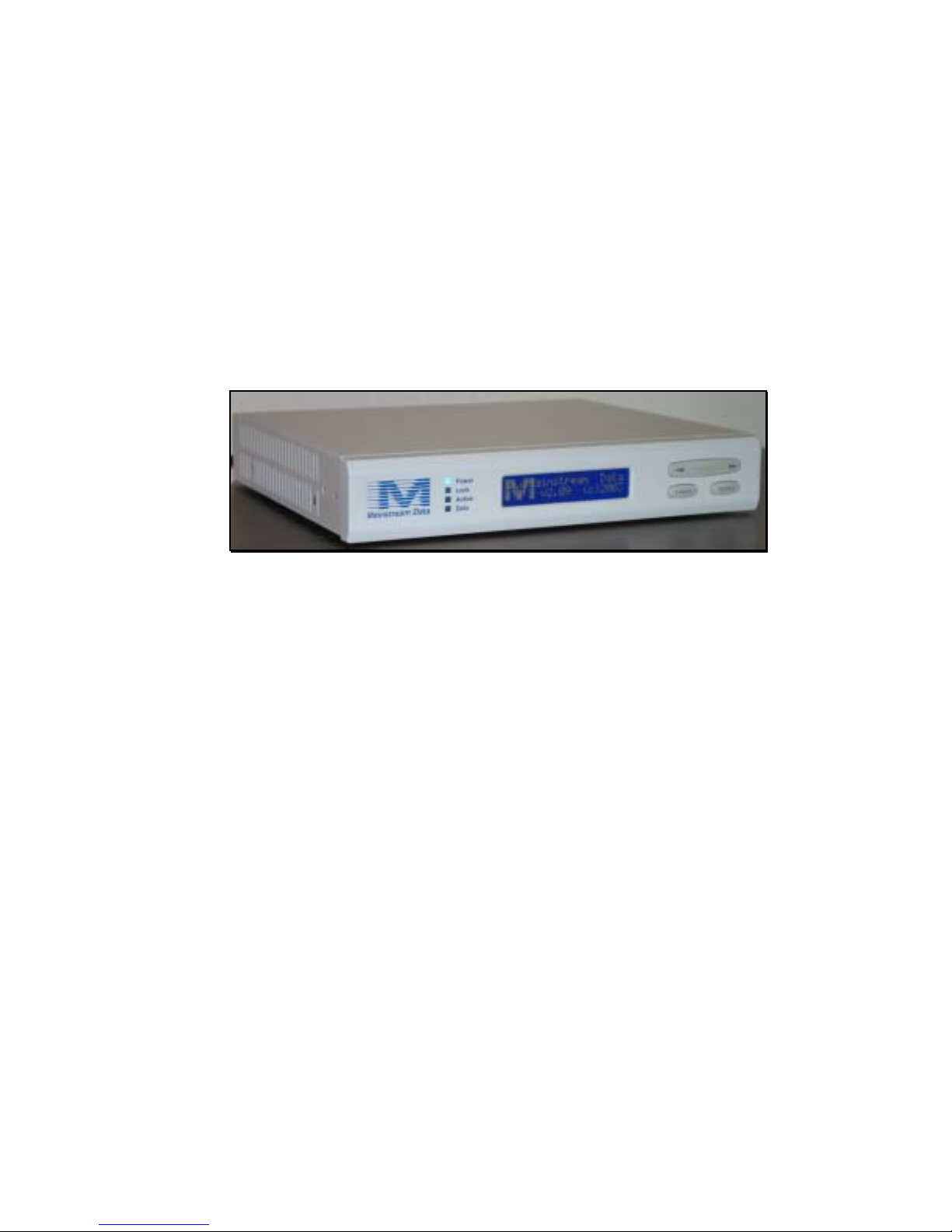
DVB+ Satellite Receiver: Overview
The Mainstream Data DVB+ Receiver, shown in Figure 1, tunes and demodulates a Digital
Video Broadcast-S, L-band RF signal input to provide data output. The DVB+ extracts IP
multicast packets from MPE sections and passes them out the Ethernet port based on the
authorized Program Identification Descriptions (PIDs) and multicast addresses. In addition, the
DVB+ can pass asynchronous output data through a standard serial port.
Note: Throughout this guide, the DVB+ Satellite Receiver is referred to simply as the “DVB+” or “the
receiver.”
Figure 1 The DVB+ Satellite Receiver
Features of the DVB+ Satellite Receiver
Features of the DVB+ include the following:
• DVB-S compatibility
• 40 Mbps of sustained throughput
• 32 PID and 32 multicast address filtering
• Traditional Mainstream Data IDR support over DVB channels
• Configurable via front panel buttons and LCD, Web interface, or over-the-air network
download
MS4966 Rev 1.2 1
Page 8

Safety Issues and Precautions
Protect yourself and help keep the DVB+ operating without disruption by following basic,
common sense procedures.
Do:
• Unplug power before changing external cables. This reduces the chance of electrical shorts
that could damage the receiver.
• Protect the DVB+ from liquids and excessive heat, humidity, or dust. These elements can
damage the processor electrical components.
• Connect the DVB+ only to grounded power outlets.
Do Not:
• Open the casework. Nothing inside the DVB+ is field-repairable. (Opening the case voids
the Mainstream Data equipment warranty.)
• Stack the receivers. Vents in the DVB+ casework are designed to provide the necessary
ventilation to the components. While the footpads on the receiver may help provide
sufficient space for ventilation, stacking is not recommended.
Documentation and Customer Support
This guide provides the high level information needed to understand the DVB+ Receiver in its
operational context. Site- or customer-specific information is not provided here. Typically a
Mainstream Data customer service representative or a network operator supplies the detailed
settings, procedures, and contact number for specific sites.
2 MS4966 Rev 12
Page 9

Installing the DVB+ Satellite Receiver
This section summarizes the steps involved in setting up the DVB+ Satellite Receiver. After
cables are connected, you will need to verify or establish DVB+ settings through the front
panel LCD. This information is covered in the next section, “Understanding DVB+ Settings”
Note: If you do not yet know the expected Eb/N0 reading and AGC levels for the site, contact the network
operator now.
Caution: Rain, snow, high winds, or extreme cloudiness can attenuate the signal. Try to avoid installing the
receiver during inclement weather, if possible, to minimize installation difficulties.
Before You Install the DVB+
Verify the following conditions:
1. A suitable satellite dish (with proper grounding) is already installed.
2. Coaxial cable is already run from the dish to the receiver location. (RG-6 cable is
recommended, length not to exceed 300 feet.)
3. RF coaxial cable shield is connected to earth ground with a #10 gauge (or heavier) solid
copper wire at the point of entry to the building.
4. RS-232 serial cable is shielded, with shield wire attached to connector shell at both ends
of the cable. Cable is “straight-through” (not NULL modem) if attaching directly to a PC
COM port.
5. Ethernet cables are of CAT-5 quality.
6. Power module is not yet connected to the DVB+.
Caution: : To prevent accidental shorts from causing circuit damage, the power module should always be
disconnected during installation or whenever cables are being changed.
MS4966 Rev 1.2 3
Page 10
Step-by-Step Procedures
Installing and verifying DVB+ operation requires use of the LCD front panel. If you have not
previously installed Mainstream Data receivers or are unfamiliar with using the front panel, refer
to the next section, Understanding DVB Settings for the appropriate information on using the
panel.
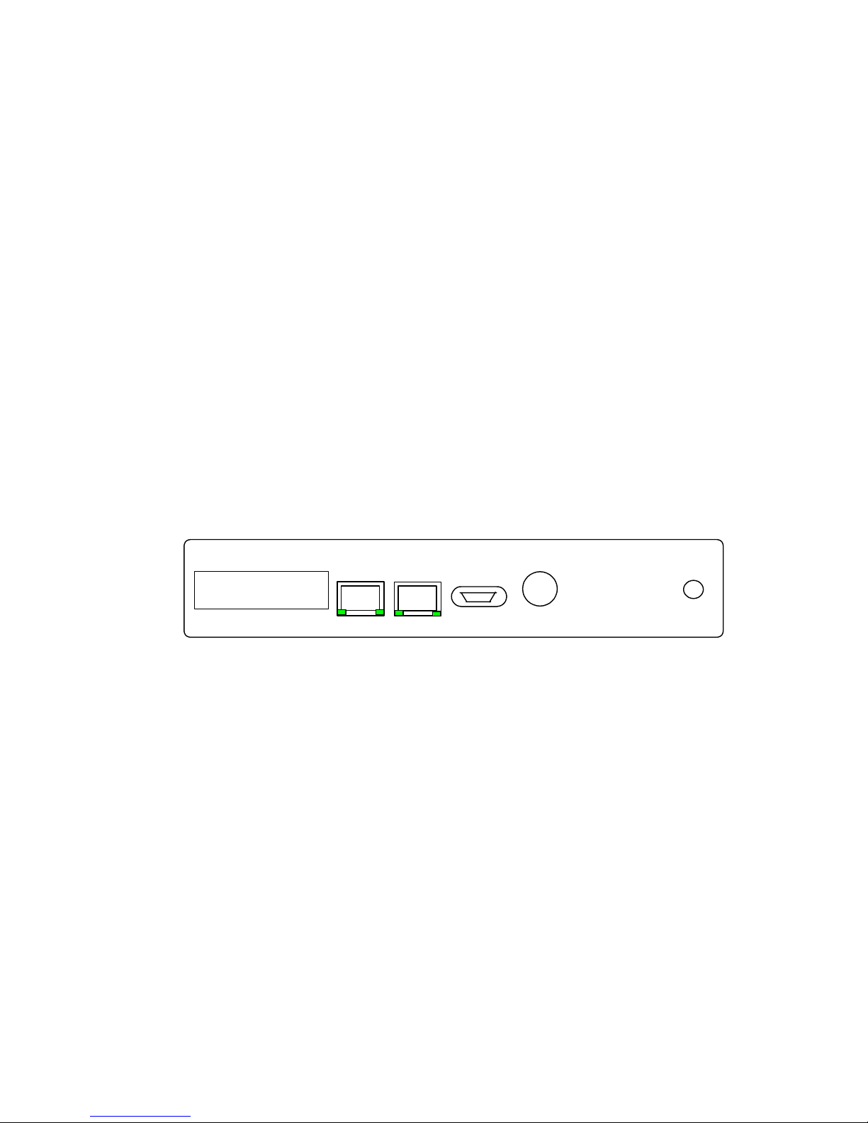
Step 1: Connect the cables
1. Connect the coaxial cable to the RF Input connector.
2. Connect a RS-232 asynchronous cable to the Serial port to view traditional IDR-type
receiver data. (This port operates similarly to previous Mainstream Data IDR models.)
3. Connect an RJ-45 Cat-5 Ethernet cable to the DVB Channel port. This is the high-
speed connection delivering multicast content.
Note: If you are connecting directly to a PC instead of to a network hub, use the supplied cross-over
cable.
4. Connect an RJ-45 Cat-5 Ethernet cable to the Aux Channel port and to a PC if you
want to view or configure the DVB+ using a Web browser, such as Internet Explorer.
Note: If you are connecting directly to a PC, use the supplied cross-over cable.
5. Connect the power module to the DVB+ power input and to the power source.
Aux
Channel
Product of Mainstream Data, USA
Figure 2 Rear Panel of the DVB+
On power-up, first the Power LED lights, then the remaining LEDs light and all flash once,
then the Power LED alone remains lit; simultaneously, a right and left LED in both the Aux
Channel and DVB Channel ports flash once. At power-up the port LEDs flash once: the left
LED means Link is UP; the right LED means Speed = 100Mbps.
When the DVB+ is booting, and during operation, the meaning of the right LED on each port
changes to indicate transfer (TX) activity.
DVB
Channel
Serial
Power
This equipment complies with the requirements in
Part 15 of the FCC rules for a Class A computing
device. Operation of this equipment in a residential
area may cause unacceptable interference to radio or
television reception, requiring the o p erator to take
whatever steps are necessary to correct the s ituation.
RF Input
4 MS4966 Rev 1.2
Page 11
Step 2: Verify Initial Lock on Carrier
As soon as power is applied to the DVB+, an automatic self-test runs. The DVB+ then
attempts to locate and lock onto the preset carrier.
If a DVB carrier is not found the DVB+ toggles back and forth between the primary and the
alternate carrier until a lock is obtained on one of the channels. The receiver stores the last
known “good” channel carrier, and a subsequent reboot first tries to achieve lock on that
channel. If no alternate carrier has been specified in the receiver setup, the receiver attempts to
lock to the primary carrier until lock is achieved or the box is powered off.
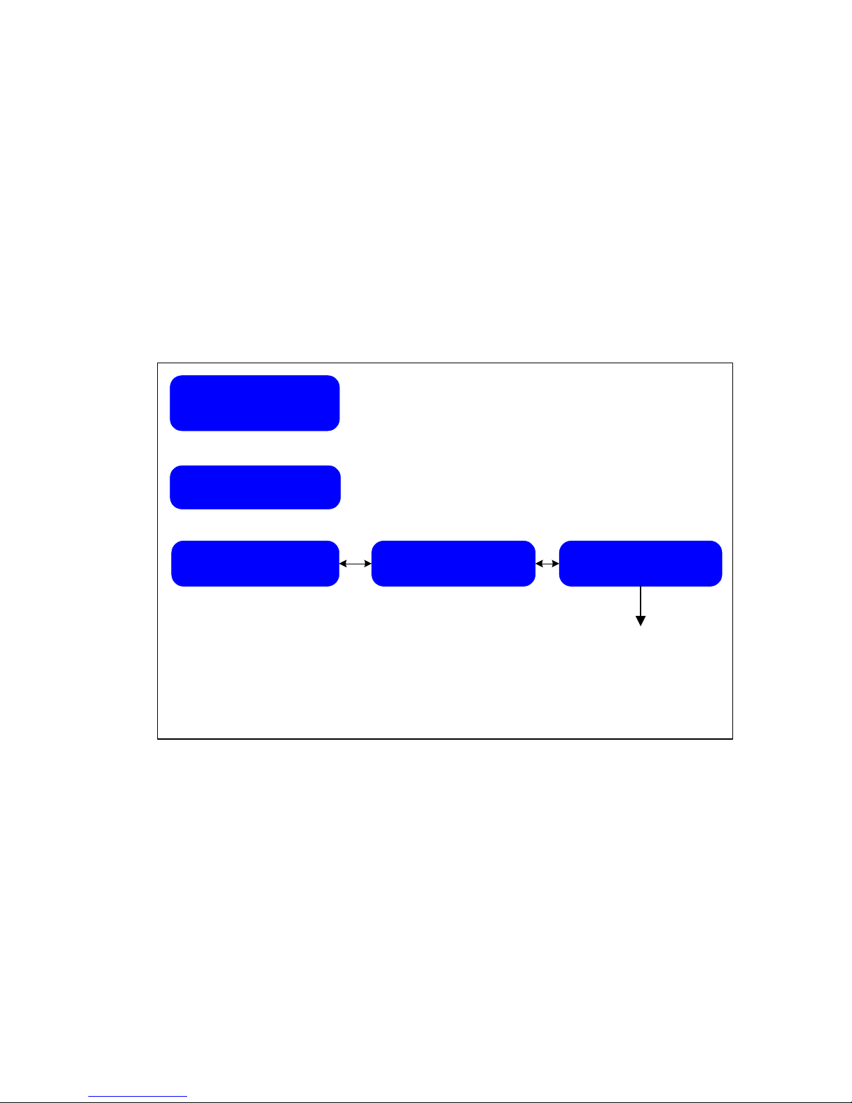
To verify the receiver is locked to the preferred carrier, check the blue Lock LED on the front
panel and also the Show Status>Show Tuner Status LCD screens. Figure 3 shows the screen
location of the applicable status settings.
ainstream Data
M
v2.22 (c)2003
Press Select
Choose Operation
Show Status
Press Select
Show
IDR Channel Status>
Show
< IP Channel Status>
Figure 3 LCD Show Status Screens Used in Installation
Show
< Tuner Status
* AGC
* Channel used
* Eb/No
* Locked/not locked
* Raw bit error rate
* Carrier frequency
* Corrected bit counts
MS4966 Rev 1.2 5
Page 12

Step 3: Verify Signal Strength
Signal strength quality is indicated mainly by the Eb/N0 reading in the Show Tuner Status
screen. It is possible to fine tune that reading by slightly adjusting the position of the satellite
dish. The Eb/N0 should be at least 5.0, usually higher, depending on environmental conditions.
(Your site will have specific requirements.)
The AGC level indicates the signal strength at the input of the tuner and can be used to verify
that the cabling is complete and the LNB is getting power from the DVB+. The reading should
be within a range of 800 to 1020, with 1000 being typical. If the number is under 800, check the
coaxial cable connections and the LNB on the satellite dish.
Step 4: Call Customer Service for Network Download
If your DVB+ is designated for a network download, your customer service representative can
arrange for the Network Operations Center to download the appropriate configuration for your
site.
Once the Eb/N
and AGC readings are at the expected levels and the Eb/N
0
has been
0
maximized by adjusting the dish alignment, notify your customer service representative.
Your customer service representative may provide you with additional instructions following
the download.
Note: If the DVB+ was pre-configured at the factory, the necessary settings may already be established and do
not need to be downloaded. Verify this with your site coordinator.
6 MS4966 Rev 1.2
Page 13

Step 5: Verify Data Output
If you are using the Serial port, you can verify its data output by performing various test
functions:
1. Request a test transfer from the NOC.
2. Connect the RS-232 cable to a computer and run Windows HyperTerminal to check
receiver settings.
3. Load a feed from a data provider to the test computer, and receive the file in
HyperTerminal.
To verify data output from the Aux and DVB Channels after cables are connected:
1. Check the link lights on the ports. The left indicator shows that the link is up, meaning
the Ethernet cable has properly connected; the right indicator shows transfer activity.
2. Check the Aux Channel port by setting up a connection between the receiver and a PC.
Set up a Web browser on the Aux Channel (see Using the Web Browser Interface) and
browse the DVB+ home page. (You need the IP addresses for both the receiver and the
PC to do this. Refer to the DVB+ View Aux LAN Setup LCD screen to view the IP
address of the receiver.) If necessary, “ping” the receiver to check that cable connection
is good.
3. Run a valid data feed through the DVB Channel Ethernet port while monitoring with a
suitable client PC application.
Corrective Actions and Status Monitoring
If data output through any of the channels is not as expected, first recheck the Eb/N
and AGC
0
readings and then perform alignment corrections as needed.
Refer to the next section for descriptions of various status and setup LCD screens that provide
useful information: the Show Status>Show IDR Status screen, shows the critical statistics for
stat mux operation. The Show Status>Show IP Channel Status screens show the critical
statistics for multicast operation.
Step 6: Maintain the Equipment
Satellite transmission can be adversely affected by bad weather. High winds can knock a satellite
dish out of alignment, and heavy snows, rain, or cloud cover can severely diminish signal
quality. You, or another designated individual at your site, should attend to the following
maintenance activities:
• Check satellite dish alignment by monitoring the E
• Remove snow from the satellite dish using a stiff whiskbroom.
• Make sure snow doesn’t accumulate on the dish and that the feedhorn window is clear.
following heavy or gusty winds.
b/N0
MS4966 Rev 1.2 7
Page 14

8 MS4966 Rev 1.2
Page 15
Understanding DVB+ Settings
All DVB+ receivers are pre-configured with a unique Ethernet MAC address and unique
Mainstream Data identification number, at a minimum. In addition, depending on specific
network or customer requirements, various features or services (other than the MAC address
and MSD ID) can be adjusted when the receiver is installed.
These factory settings can be changed after installation, in three ways or combinations thereof:
• Front panel with LCD display and pushbuttons
• Web browser interface
• Network download, using the optional NMS (a network-dependent option)
The DVB+ front panel is designed similarly to previous Mainstream Data receiver models;
current receiver users will be familiar with the 2-line display and tree structure of the menu
options. The front panel LCD and keypads are necessary at installation to set and achieve a lock
on the RF signal. Once the DVB+ is set up, subsequent configuration changes can be
downloaded from the Network Operations Center or entered through the Web browser
interface, as well as through the front panel.
Current settings can be viewed on the front panel or through the Web interface.
This section discusses how to use the front panel and the Web interface and how to interpret
the screens that are displayed.
Using the Front Panel
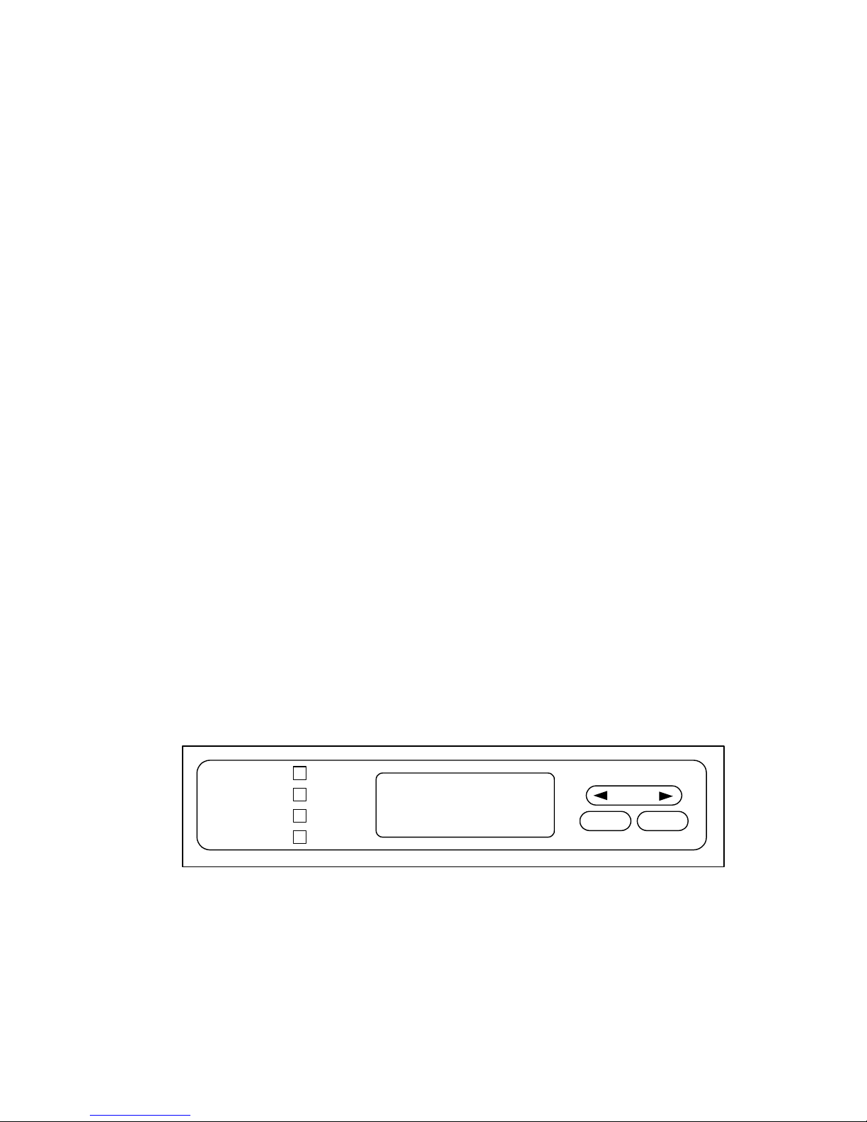
You can view and modify configuration settings, as well as view dynamic performance of the
DVB+ from the front panel LCD. Once you become familiar with the usage of the buttons,
this 20-character-by-2-line display provides a direct and intuitive interface to the DVB+
functions.
Power
Lock
Active
Data
Figure 4 Front Panel Indicators, LCD Screen, and Keycaps
Cancel Select
MS4966 Rev 1.2 9
Page 16
Front Panel Indicators
When power is first applied, the four indicators --- Power, Lock, Active, and Data--- flash
twice. The Power indicator stays lit while the DVB+ is booting. If signal lock has been
achieved, the Lock indicator stays lit.
The Active indicator is triggered when any valid packet is received from any PID. The Data
indicator lights when stat mux data is actually output through the Serial port or when DVB data
is output through the Ethernet port (Basically, the Active indicator shows that the DVB+ and
its satellite feed are functioning; the Data indicator shows that you are receiving usable data.)
LCD Screen
The Mainstream Data identification screen displayed after the receiver finishes its initial startup
procedure is the “home page” of the front panel. Pressing the SELECT button moves the
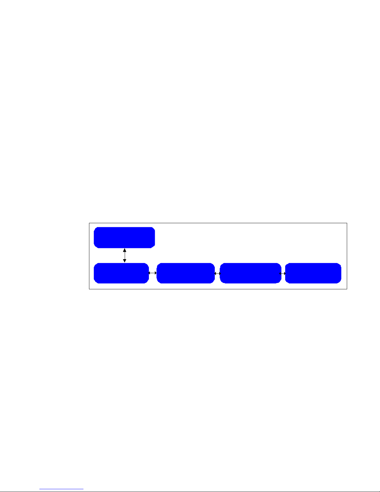
display to the first of four main stems of the menu “tree.” The four main stems are:
• Show Status
• View Setup
• Specify Setup
• Utilities
ainstream Data
v2.21 (c)2003
M
Choose Operation
Show Status >
Choose Operation
< View Setups >
Figure 5 Top Level of Menu Tree
Navigating the Menu Tree
The front panel buttons are used for two functions: navigating the tree of screen displays and
entering new values:
• Press the SELECT button to drill down into the contents under either main stem.
• Use the left and right arrows to move within a stem.
• Press the CANCEL button to move back up towards the top of the tree.
Choose Operation
< Specify Setups >
Choose Operation
< Utilities
10 MS4966 Rev 1.2
Page 17

Entering and Changing Values
Some screens are designed for entering new values or for modifying existing values.
• Use the arrow buttons to increment or decrement the value displayed above the cursor.
• Press SELECT to advance the cursor to the right.
• Press CANCEL to move the cursor to the left.
Once the cursor is moved to the rightmost position, press SELECT again to store the value.
Invalid entries are not accepted by the DVB+. For example, if you try to enter the first byte of
an IP address as 257 (where the maximum allowable value is 255), the entry is rejected.
Overview of LCD Displays
Some LCD screens are static, meaning the screen is painted once upon entry and does not
change thereafter. However, some screens are dynamic, allowing variables, such as AGC, to be
observed in real time.
Note: Dynamic screens consume processor time, which reduces the available capacity for data processing.
Although the same current settings are displayed within the Specify Setup subordinate screens,
it is preferable to view the receiver setups only from the View Setup screens. An inadvertent
keystroke within Specify Setup could modify an important setting. Even more problematical,
features listed under Utilities usually place the receiver into a special mode, many of which can
disable data output.
Caution: Changes made within the
Specify Setup
and
Utilities
screens can disrupt system output.
Table 1 Summary of Menu Topics Accessible through LCD Front Panel
Menu Topics Page
Show Status:
Press the SELECT button from the Show Status screen to access the following displays.
Show IDR Channel Status
Mainstream Data ID number and timestamp
•
• Logical receiver 0, Serial 1 output status and flow control
• TVC/PVC status
• Stat mux “superscreen” containing packet counters, error counters, buffer
and processor information
Show IP Channel Status
•
MPEG frames, MPE/second, and IP output packets
• Speed, Link status, and Transmission status
Show Tuner Status
•
AGC voltage, Channel, and Eb/No
• Signal lock status, code rate
• Raw error bit rate
• Carrier frequency
• Corrected bits, uncorrected blocks, and signal lock drops
• Corrected bits and corrected bit rate
14
15
16
17
MS4966 Rev 1.2 11
Page 18

Menu Topics Page
View Setups:
Press the SELECT button from the View Setups screen to access the following displays:
View IDR Channel Setup
•
Logical receiver 0, Serial 1 default or not default destination, Pad or
Node, baud rate, bits per word, parity, stop bits, and flow control
• View pools and groups
• View PVC numbers
View IP Channel Setup
PID table
•
• Bypass mode on or off
• Multicast table
• High speed group codes
• IP remap table
• DVB MAC address
View Tuner Setup
Main and alternate RF channel tuner frequency
•
• Symbol rate
• Modulation
• Channel PID
• LNB voltage/22kHz tone
• Channel mode (enable/disable)
View Auxiliary LAN setup
• DHCP usage
• IP address
• Subnet mask
• Default gateway
• Aux channel MAC address
View Serial 1 Setup
• Baud rate, bits/word, parity, stop bits, flow control
Specify Setup
Caution: Changing values within this menu modifies the DVB+ operation.
Press the SELECT button from the Specify Setups screen to access the following displays:
Specify IDR Channel Setup
• Serial 1 default or not default destination
• Serial 1 attributes: Pad or node
Baud rate
Data bits
Parity
Stop bits
Flow control
Specify IP Channel Setup
Review, add to, or remove from PID table, or change a DVB key for a PID
•
• Configure bypass mode
• Review, add to, or remove from multicast table
• Review, add to, or remove from IP remap table
Specify Tuner Setup
Main and alternate RF channel tuner frequency
•
• Symbol rate
• Modulation
• Channel PID
• LNB voltage/22kHz tone
• Channel mode
18
18
19,20
21,22
23
24
25
25
26
27
12 MS4966 Rev 1.2
Page 19
Menu Topics Page
Specify Auxiliary LAN setup
DHCP usage
•
• IP address
• Subnet mask
• Default gateway
Specify Com Port Settings
Baud rate
•
• Data bits
• Parity
• Stop bits
• Flow control
Reinstall Factory Settings
28
29
30
31
Utilities
Press the SELECT button from the Utilities screen to access the following displays
Select Audio Alignment
On/off
•
Select Output serial data
Select Stat Logger
• On/off
Select Software Update Monitor
Software update status
•
• Checksum; image
Select System Reboot
Initiate manual reboot
•
Select Status Packet
• Report rate
• IP address
• Port number
31
31
31
31
31
31
The following pages illustrate and describe these LCD screens in detail.
Note: Depending on specific configurations required by your site, all the LCD screens discussed in this document
may not be visible or modifiable as described. See your site coordinator or customer service representative if
the DVB+ screens do not appear or do not function as you expect.
MS4966 Rev 1.2 13
Page 20
Interpreting Screens
This section describes how and when to use the screens to monitor or specify settings on the
DVB+.
Show Status Screens
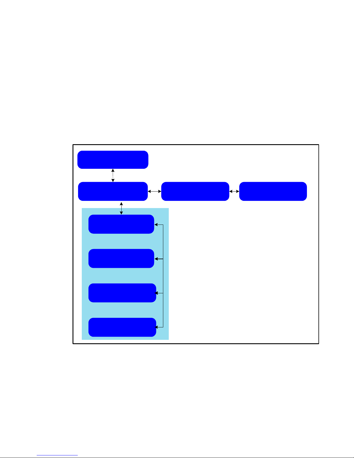
If you press SELECT once from the Mainstream identification screen, the “home page”, you
display the SHOW STATUS menu.
1. Press SELECT again to display the IDR Channel Status screen.
2. Press SELECT again to display the screens you can view within IDR Channel status.
Choose Operation
Show Status
Show
IDR Channel Status>
Base MSDId 14xxxxxx
Awaiting timestamp
R0: SERIAL1 Status
<Not active> RTS Off
Active TVC: 0
Enabled PVC: 0
0 0 0 0 0
0 0 0 0
Figure 6 Show IDR Channel Status
Show
< IP Channel Status>
Show
< Tuner Status
Note: Showing IDR Channel status is a network-specific option requiring Mainstream Data NMS.
14 MS4966 Rev 1.2
Page 21

Table 2 Show IDR Channel Status Fields
Indication: Description: Notes:
Base MSD ID and
timestamp
R0=logical receiver 0
Serial 1 = Not active
Serial 1 = Active
Serial 1 = Capture
RTS On/Off
Active TVC:
Enabled PVC:
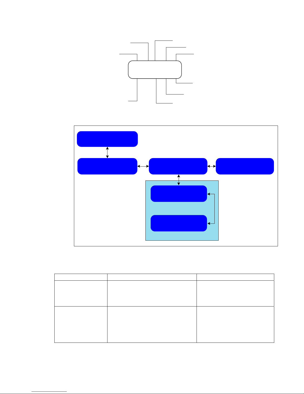
Stat mux Superscreen See Figur e 7
Mainstream Data ID number by which the
NOC identifies this machine for
downloading configurations.
Timestamp is Greenwich Mean Time
(GMT). When the DVB+ is receiving
transmissions from the Mainstream Data
NOC, the displayed time updates
continuously and is synchronized every 5
minutes
Serial 1 port output status and flow control “Capture” displays when DVB+ is
Currently active and open temporary
virtual circuits (pools and groups)
Permanent virtual circuits are always
open.
“Packets received” should be
incrementing when the receiver is locked
and receiving MSD data(serial port data
only).
CRC, Input Filter, and Session Errors are
counters.
“Memory unavailable” count means the
number of times internal memory was
requested but was unavailable.
“Current bytes in input buffer” shows realtime activity.
“Maximum bytes received in input buffer”
maintains the record of the highest
number of bytes held in the input buffer.
A DVB+ not connected to the
satellite dish or receiving
transmissions from a different
source would display “awaiting
timestamp.
Time increments between screen
updates. A blinking colon indicates
that an update has been received in
the last six minutes.
outputting a first PAD session and
storing a second session. The
second session is sent out after the
first completes.
Both TVCs and PVCs can be
enabled or disabled by download.
CRC, Input Filter, and Session
Errors typically do not increment but
also do not necessarily indicate bad
or lost data.
Current input buffer generally
changes from 0 to a large number
as packets are received and
processed.
MS4966 Rev 1.2 15
Page 22
CRC errors
Packets
received
Input Filter error
Session error
Memory unavailable
count
xxx x x x x
xxx xxx x x
MSD diagnostic only
Current bytes in input
buffer
MSD diagnostic only
Maximum by tes received
in input buffer
Figure 7 Stat Mux “Superscreen” in IDR Channel Status Display
Choose Operation
Show Status
Show
IDR Channel Status>
Show
< IP Channel Status>
Show
< Tuner Status
Figure 8 Show IP Channel Status
Table 3 Show IP Channel Status Fields
Indication: Description: Notes:
MPGfrm
MPEsec
IP packets
Speed
Link
TX Active
MPEG frame counter
MPE section counter
IP packet counter of address matches
Shows the DVB Channel connected line
speed
Shows DVB Channel link is up or down
Shows output data transfer is active or not
active
MPGfrm MPEsec IPpkt
000000 000000 000000
Speed Link TxActive
10 bt Down No
Does not increment in IP bypass
mode (as addresses are not being
checked)
If the DVB+ is in bypass mode, the
TX Active may be “yes” even when
IP Packet counter does not
increment. See note above.
16 MS4966 Rev 1.2
Page 23
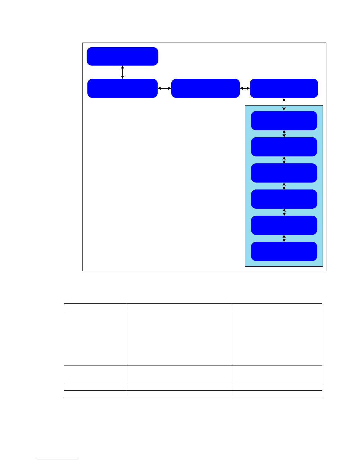
Choose Operation
Show Status
Show
IDR Channel Status>
Show
< IP Channel Status>
Show
< Tuner Status
AGC Chan Eb/No >
xxx main xx.xxdB
< Lock / Code Rate>
Lock xxx
< Raw Bit Err Rate>
0.0000
< Carrier Frequency>
XXXXXXMhz
<CBits UBlks LckCnt>
00000 0000 0000
<CBits CBitRate
000000 0.0E+00
Figure 9 Show Tuner Status
Table 4 Show Tuner Status Fields
Indication: Description: Notes:
AGC
Chan
Eb/No
Lock/code rate Lock = Signal lock
Raw bit error rate Log of all errors, corrected or not
Carrier frequency Current lock frequency
Automatic Gain Control
Indicates which channel (Main or
Alternate) the receiver is using to acquire
lock
Indicates relative signal quality of desired
DVB-S carrier
Code rate = rate embedded in downlink
carrier
Relative reading of absolute signal
strength at the input to the tuner.
Should be between 800-1020.
Should be at least 5 for reliable data
transmission, probably higher
Viewable code rates are 1/2, 2/3,
3/4, 5/6, 6/7, and 7/8.
MS4966 Rev 1.2 17
Page 24
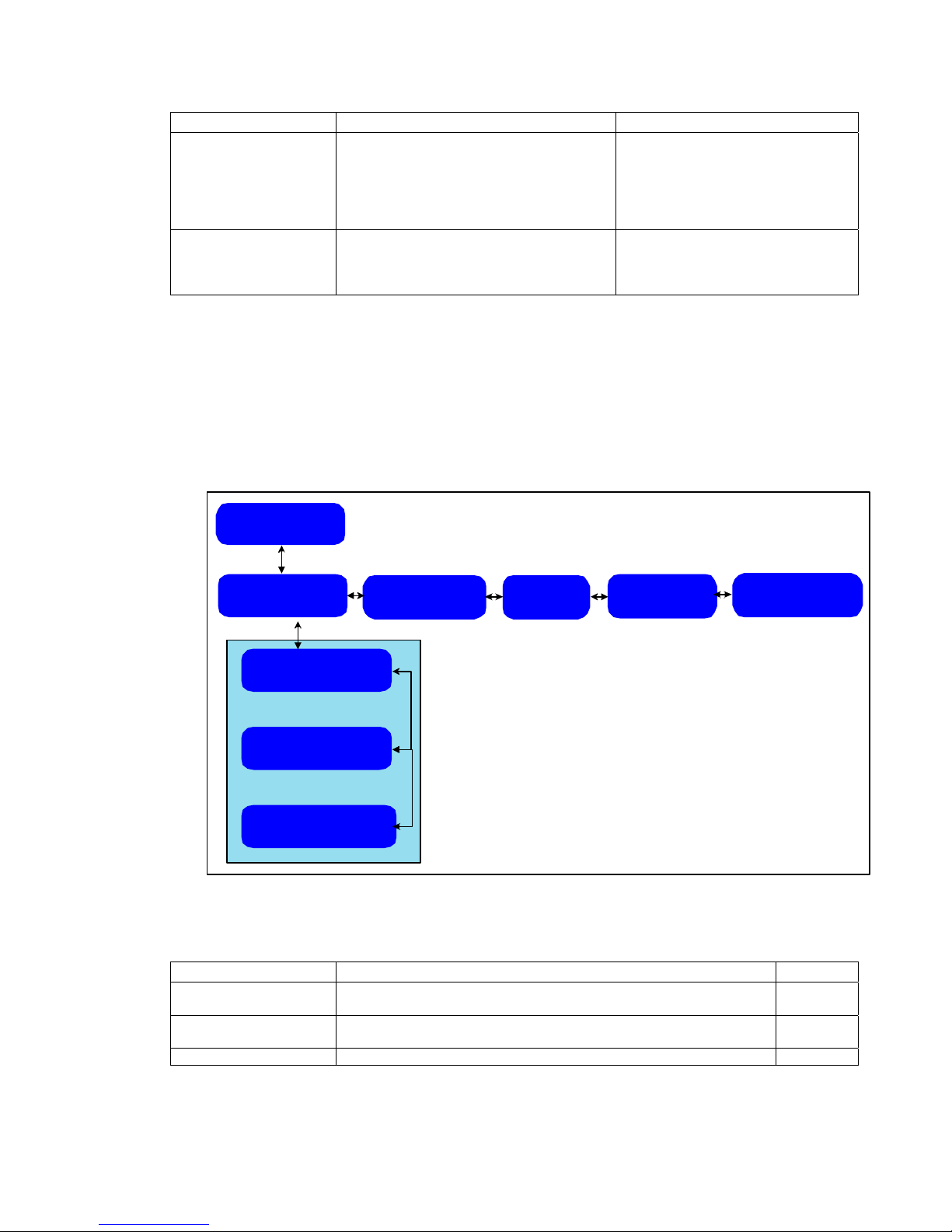
Indication: Description: Notes:
Cbits
Ublks
Lck cnt
CBits
CBitRate
Corrected bits
Uncorrected blocks
Lock count
Number of bits corrected by Reed-
Solomon decoder.
Effective bit error rate before ReedSolomon error correction/decoding
Corrected bit counters provide
useful diagnostics if data is not
being received as expected.
Number of times signal lock was
lost since the last reset
Same information as CBits above.
View Setups Screens
The View Setups screens show the current configuration in effect for the DVB+. To reach
these screens from the home page:
1. Press SELECT once from the Mainstream identification screen
2. Press the right arrow from the Show Status screen.
3. To enter the View Setups tree, press SELECT again.
Choose Operation
View Setups
View
IDR Channel Setup
R0: SERIAL1 Def/Pad
115200 8/None/1 RTS
View Pools/Groups
View PVC Numbers
View
IP Channel Setup
Figure 10 View IDR Channel Setup Screens
Table 5 View IDR Channel Setups Fields
View
Tuner Setup
View
Aux LAN Setup
View
Serial 1 Settings
Indication: Description: Notes:
R0 Serial 1 R0 Serial 1 Destination, pad or node mode, baud rate/d ata
View Pools and Groups Designated set of pools and groups for which DVB+ is allowed to
View PVC numbers Designated PVCs for which the DVB+ is allowed to receive data
18 MS4966 Rev 1.2
bits/parity/stop bits, flow control mechanism
receive data
Page 25
Choose Operation
View Setups
IDR Channel Setup
View
View
IP Channel Setup
View
PID Table
Bypass Mode:
View
Multicast Table
View
HS Group Codes
View
Tuner Setup
View
Aux LAN Setup
Serial 1 Settings
View
View
IP Remap Table
View
DVB MAC Address
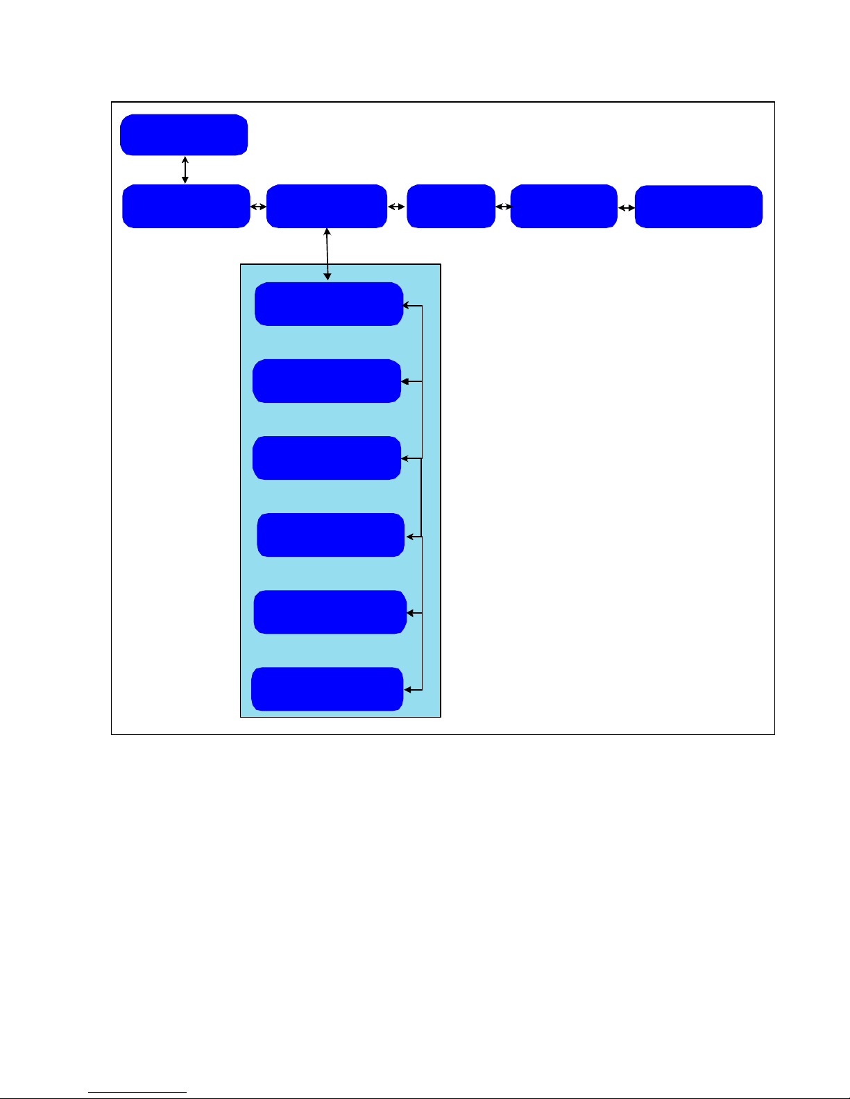
Figure 11 View IP Channel Setups Screens
MS4966 Rev 1.2 19
Page 26

Table 6 View IP Channel Setups Fields
Indication: Description: Notes:
PID table Press the right arrow key to display up to
the maximum of 32 PIDs configured.
(Press the left arrow key to jump from the
first PID to the last.)
Each PID is made up of 1 to 4 digits,
displayed in hexadecimal numbers.
Bypass Mode Displays either “Use Mcast (multicast)
Filters” or “Pass All Packets”.
Multicast table When you press SELECT from View
Multicast Table, you see 0 to 32 (max)
multicast addresses configured. Press the
right arrow key to move through
subsequent multicast address displays.
(Press the left arrow key to jump from the
first address to the last.)
HS Group Codes High speed group codes
IP remap table The table shows various source IP
address and new destination IP address
pairs.
DVB MAC address The permanent MAC address associated
with the DVB Ethernet port
Multicast addresses displayed
within the table are the addresses of
authorized channels.
Note: This feature does not operate
if the receiver is in bypass mode.
Whenever the source destination is
received, the specified destination
address is substituted.
Note: This feature does not operate
if the receiver is in bypass mode.
20 MS4966 Rev 1.2
Page 27
Choose Operation
View Setups
IDR Channel Setup
View
View
IP Channel Setup
View
Tuner Setup
View
Main RF Channel
View
Alt. RF Channel
View
Aux LAN Setup
xxx(hex) xxx(dec)
Serial 1 Settings
View
Tuner Frequency>
1152.50 Mhz
Symbol Rate
x.xxx MBd
Modulation
QPSK
Channel PID
LNB Voltage
18 V
Channel Mode
Enabled
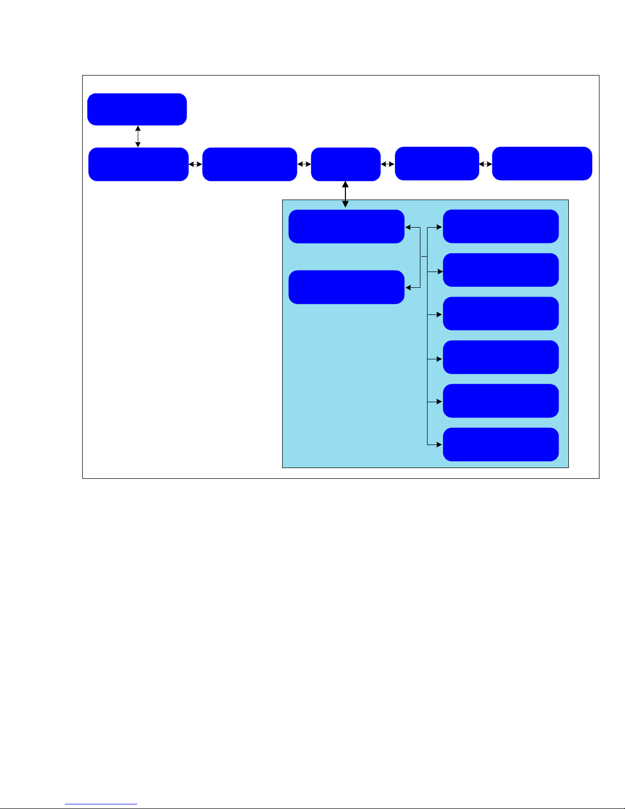
Figure 12 View Tuner Setups Screens
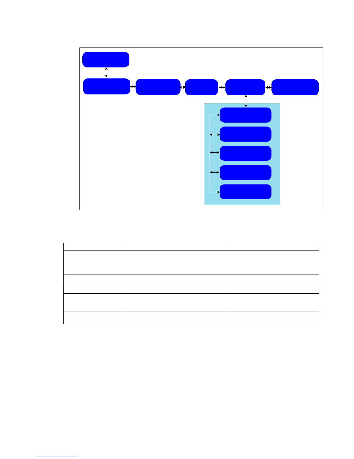
Two subordinate screens within the View Tuner Setup tree show the tuner parameters for both
a main and an alternate RF channel. The alternate channel serves as a backup if the main carrier
fails for any reason. If both main and alternate channels are enabled, the receiver toggles back
and forth until a lock is obtained on one of the channels. The receiver stores the last known
“good” channel, and a subsequent reboot first tries to achieve lock on that channel.
MS4966 Rev 1.2 21
Page 28
Table 7 View Tuner Setups Fields
Indication: Description: Notes:
Tuner frequency L-band carrier frequency the tuner is
currently monitoring
Symbol rate BPSK or QPSK symbol rate for which the
DVB+ demodulator is configured.
Modulation Allows selection of BPSK or QPSK QPSK is the only valid modulation
Channel PID PID that the control channel decoder is
currently listening to
LNB voltage/22Khz
tone
Channel mode
enabled/disabled
Displays current LNB setting
The channel is either enabled or disabled
type for early releases of the DVB+.
In later releases, BPSK is also
implemented.
Same PID for stat mux channel as
for control channel
22 MS4966 Rev 1.2
Page 29
Choose Operation
View Setups
View
IDR Channel Setup
View
IP Channel Setup
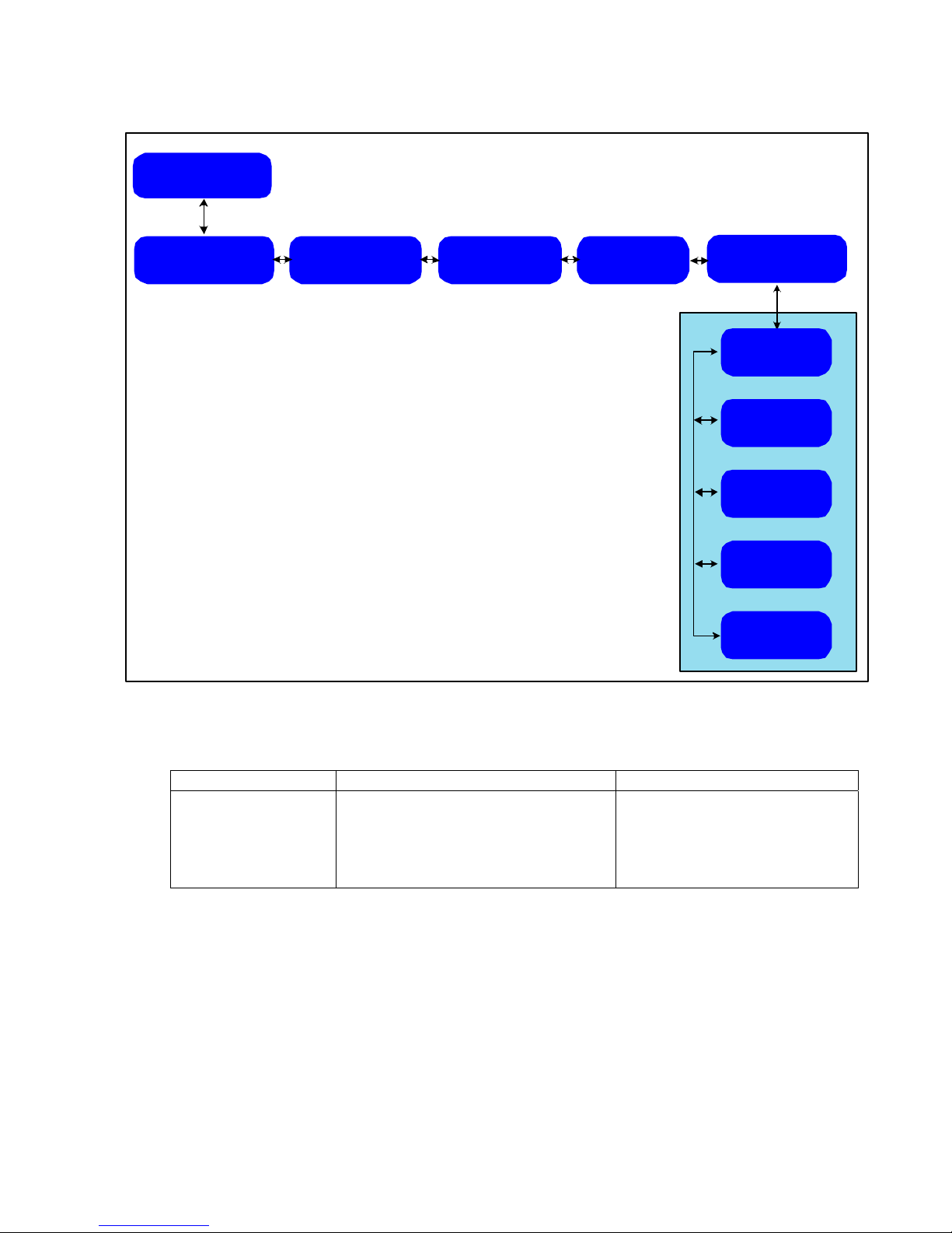
Figure 13 View Aux LAN Setups Screens
Table 8 View Aux LAN Setups Fields
Indication: Description: Notes:
DHCP Usage Enabled or disabled “Enabled” requests IP address from
IP Address Configured IP address
Subnet Mask Mask used for determining the subnet to
which the IP address belongs
Default Gateway IP address Designates where data is sent if the
Aux MAC address The permanent MAC address of the Aux
Channel output
View
Tuner Setup
View
Aux LAN Setup
DHCP Usage
IP Address
xxx.xxx.xxx.xxx
Subnet Mask
255.255.255.xxx
Default Gateway
xxx.xxx.xxx.xxx
Aux MAC Address
xx:xx:xx:xx:xx:xx
View
Serial 1 Settings
DHCP server at bootup.
“Disabled” uses configured IP
address.
target IP address does not reside on
the same subnet as the source
MS4966 Rev 1.2 23
Page 30
Choose Operation
View Setups
IDR Channel Setup
View
View
IP Channel Setup
Tuner Setup
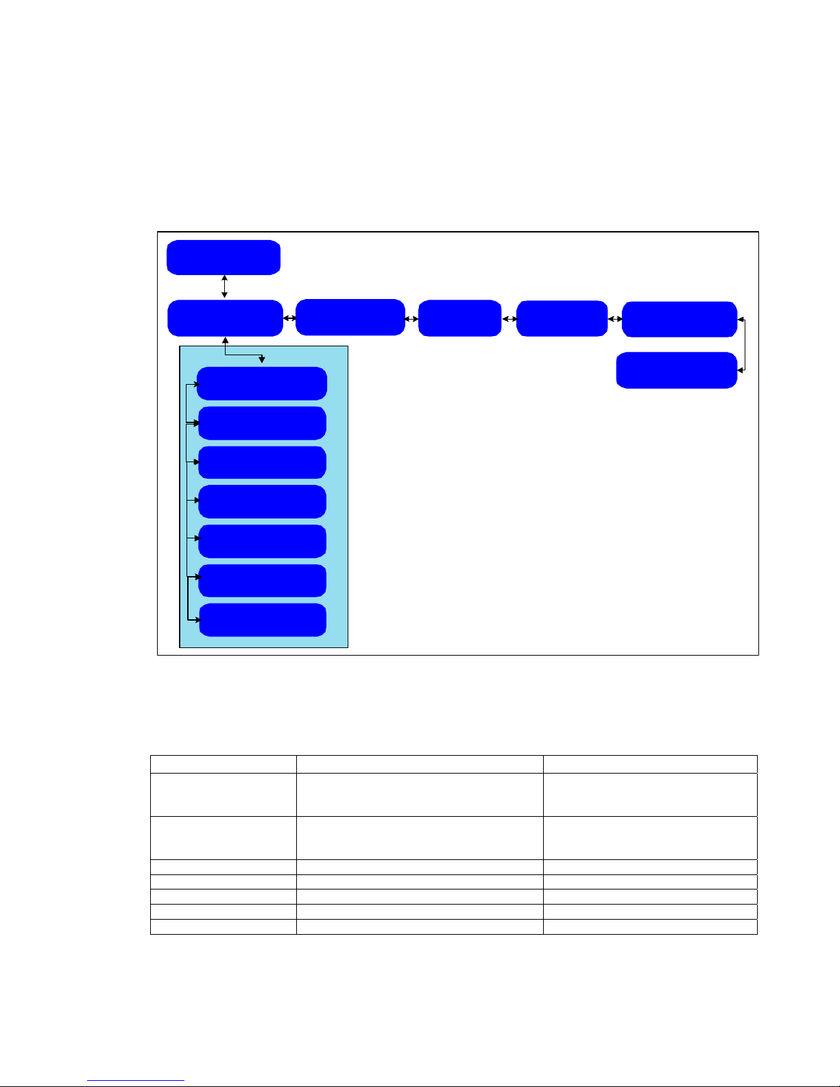
Figure 14 View Serial 1 Setups Screens
View
View
Aux LAN Setup
Serial 1 Settings
View
Baud Rate
115200
Data bits
5-8
Parity
None/Even/Odd
Stop bits
1/2
Flow control
(type)
Table 9 View Serial 1 Setups Fields
Indication: Description: Notes:
Baud rate
Data bits
Parity
Stop bits
Flow control
Communication port settings
Bit rate of Serial port
Number of bits per byte of data
Parity type used in data stream
Number of stop bits per data byte
Type of flow control used by the
communicating device
24 MS4966 Rev 1.2
Page 31
Specify Setups Screens
The Specify Setups screens are the primary means of manually entering or altering DVB+
configuration settings. The last screen in the Specify Setups sequence is the Reinstall Factory
Settings screen..
Choose Operation
Specify Setups
Specify
IDR Channel Setup
SERIAL1 destination
Default/not default
SERIAL1 attributes
Pad/Node
Baud Rate
xxxxx
Data bits
5/6/7/8
Parity
None/Even/Odd
Stop bits
1/2
Flow control
None/XonXoff/RTS
Specify
IP Channel Setup
Specify
Tuner Setup
Figure 15 Specify IDR Channel Setup Screens
Specify
Aux LAN Setup
Specify
Com Port Settings
Reinstall
Factory Settings
Table 10 Specify IDR Channel Setup Fields (Mainstream Data Network-Specific)
Indication: Description: Notes:
Serial 1 Destination Default or not Default Serial 1 is set or not set as the
Serial 1 Attributes Pad or Node Pad indicates raw transmitted data.
Baud Rate Rate of data stream
Data bits Number of bits per byte of data
Parity Parity type used in data stream
Stop bits Number of stop bits per data byte
Flow control None, Xon/Xoff, or RTS (request to send) RTS = hardware flow control
MS4966 Rev 1.2 25
default destination associated with
the Stat Mux data feed
Node indicates data with MSD node
protocol
Page 32
Choose
Operation
Specify Setups
Specify
IDR Channel
Setup
Specify
IP Channel
Setup
Specify
PID Table
Specify
Bypass Mode
Specify
Multicast Table
Specify
IP Remap Table
Specify
Tuner Setup
Figure 16 Specify IP Channel Setup Screens
Specify
Aux LAN
Setup
Specify
Com PortSetups
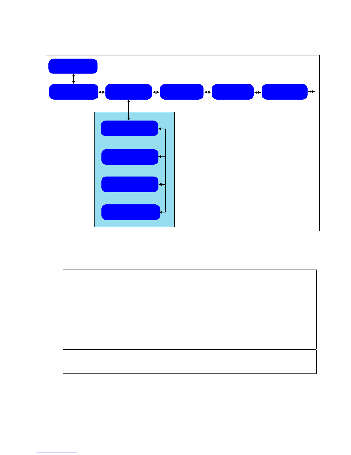
Table 11 Specify IP Channel Setup Fields
Indication: Description: Notes:
Specify PID table Review, add, or remove a PID, and
change the setting of a DVB encryption
key.
Specify Bypass Mode Select use of multicast filters or passing
all packets.
Specify multicast table Set which multicast addresses will be sent
through the DVB Channel
Specify IP remap table Set which IP multicast address will be
modified to contain a new destination IP
address
Set which PIDs are passed through
the DVB channel (to the DVB
Channel Ethernet port), along with
associated DVB keys
IP packets must pass the PID filter,
then pass through remaining filters
In “Bypass Mode,” all valid multicast
addresses are passed (if they are
received on PIDs in the PID table).
The multicast address may be
remapped to another address.
(This feature is disabled if the
receiver is in Bypass Mode.)
26 MS4966 Rev 1.2
Page 33
Choose Operation
Specify Setups
Specify
IDR Channel Setup
Specify
IP Channel Setup
Tuner Setup
Main RF Channel
Alt. RF Channel
Figure 17 Specify Tuner Setup Screens
Specify
Specify
Specify
Specify
Aux LAN Setup
Tuner Frequency>
1152.50 Mhz
Symbol Rate
x.xxx MBd
Modulation
Channel PID
0xxx (hex)
LNB Voltage
Channel Mode
Specify
Com Port Settings
QPSK
18 V
Enabled
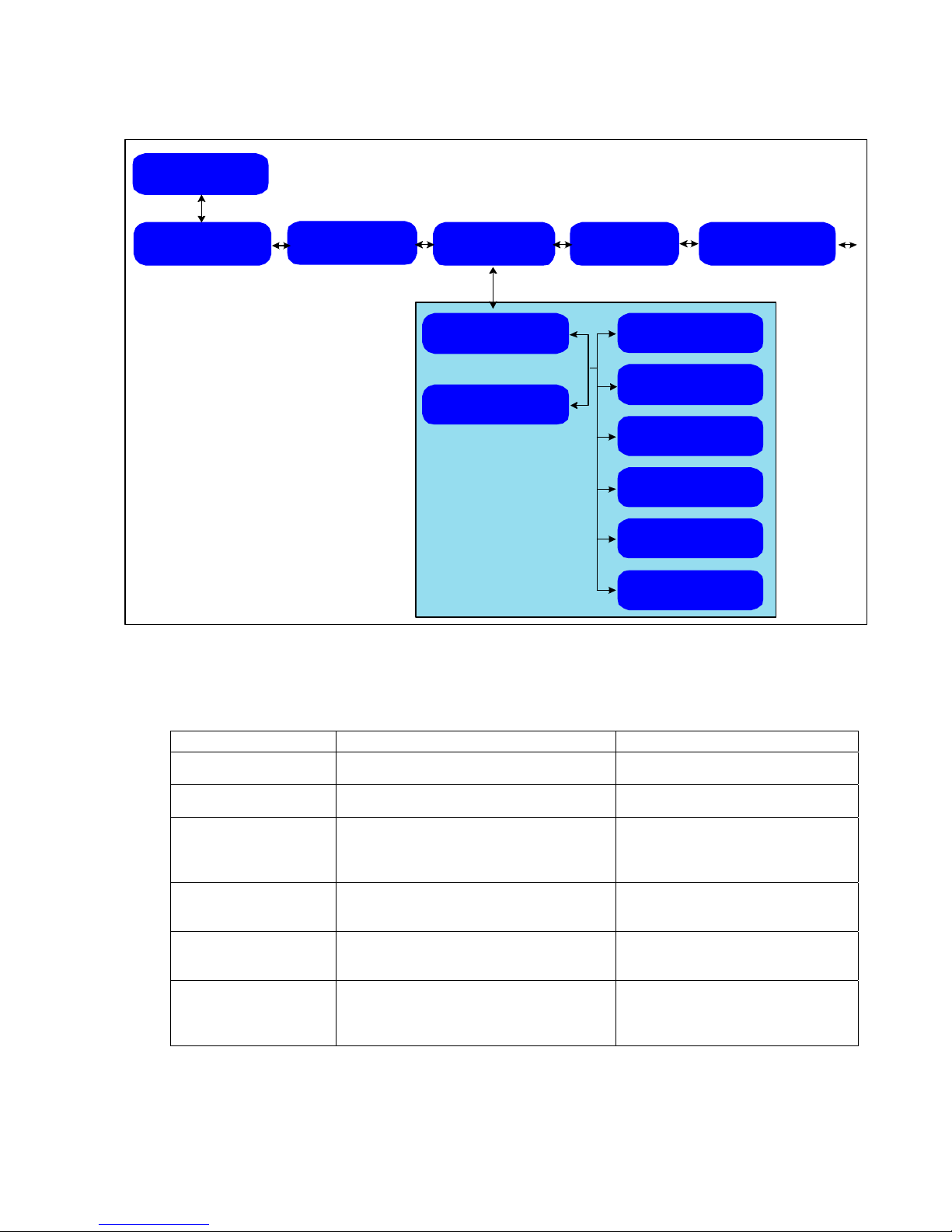
Table 12 Specify Tuner Setup Fields
Indication: Description: Notes:
Tuner Frequency L-band frequency on which the receiver
tries to acquire a valid carrier signal
Symbol Rate The symbol rate used by the receiver to
acquire a carrier signal
Modulation QPSK or BPSK QPSK is the only valid modulation
Channel PID (hex only) The PID associated with the control
channel. This is the same as the Stat Mux
channel.
LNB Voltage The value of the voltage and 22Khz
settings for the LNB installed
Channel Mode Enabled
Disabled
type for early releases of the DVB+.
In later releases, BPSK is also
implemented.
Refer to discussion in Functional
Overview
section on the DVB+
Satellite Receiver (page 43)
Uses this tuner setup to acquire
carrier.
Does not use this setup to acquire
carrier.
MS4966 Rev 1.2 27
Page 34
Choose
Operation
Specify Setups
Specify
IDR Channel
Setup
Specify
IP Channel
Setup
Specify
Tuner Setup
Figure 18 Specify Aux LAN Setup Screens
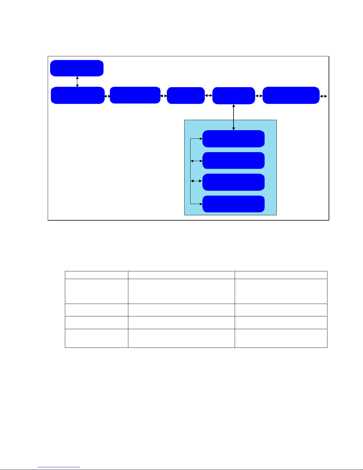
The Aux LAN setup fields affect only Aux Channel output.
Table 13 Specify Aux LAN Setup Fields
Specify
Aux LAN Setup
DHCP Usage
IP Address
xxx.xxx.xxx.xxx
Subnet Mask
255.255.255.xxx
Default Gateway
xxx.xxx.xxx.xxx
Specify
Com Port Settings
Indication: Description: Notes:
DHCP Usage Turns on/off the use of a DHCP client to
acquire the IP address parameters of the
Aux Channel.
IP address Specifies the IP address of the Aux
Channel if DHCP is not activated
Subnet mast Specifies the subn et mask of the Aux
Channel if DHCP is not activated
Default gateway Specifies the default gateway of the Aux
port only if DHCP setting in the previous
screen is not activated.
If DHCP is on, DVB+ requests at
bootup a set of Aux Channel IP
addresses from the outside DHCP
server.
Required if the PC client is located
on a different IP network segment
than the DVB+
28 MS4966 Rev 1.2
Page 35
Choose Operation
Specify Setups
Specify
IDR Channel Setup
Specify
IP Channel Setup
Specify
Tuner Setup
Specify
Aux LAN Setup
Figure 19 Specify Communication Port Settings Screens
Specify
Com Port Settings
Baud Rate
115200
Data bits
5-8
Parity
None/Even/Odd
Stop bits
1/2
Flow control
(type)
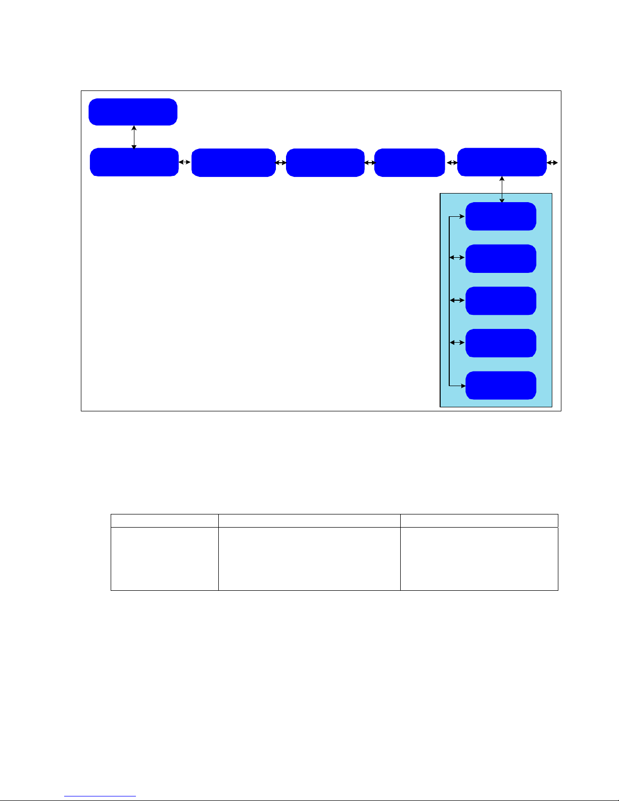
The Com Port Settings screens are where the Serial Port communication parameters are
entered.
Table 14 Specify Com Port Settings
Indication: Description: Notes:
Baud rate
Data bits
Parity
Stop bits
Flow control
Communication port settings Set rate of data stream
Number of bits per byte of data
Parity type used in data stream
Number of stop bits per data byte
Type of flow control used by the
communicating device
MS4966 Rev 1.2 29
Page 36

Choose Operation
Specify Setups
Specify
IDR Channel
Setup
Specify
IP Channel
Setup
Specify
Tuner Setup
Figure 20 Reinstall Factory Settings
The last screen under the Specify Setups menu allows you to reinstall initial factory settings to
the DVB+.
Specify
Aux LAN
Setup
Specify
Com Port
Settings
Reinstall
Factory
Settings
Press SELECT to
Reinstall
Settings
30 MS4966 Rev 1.2
Page 37
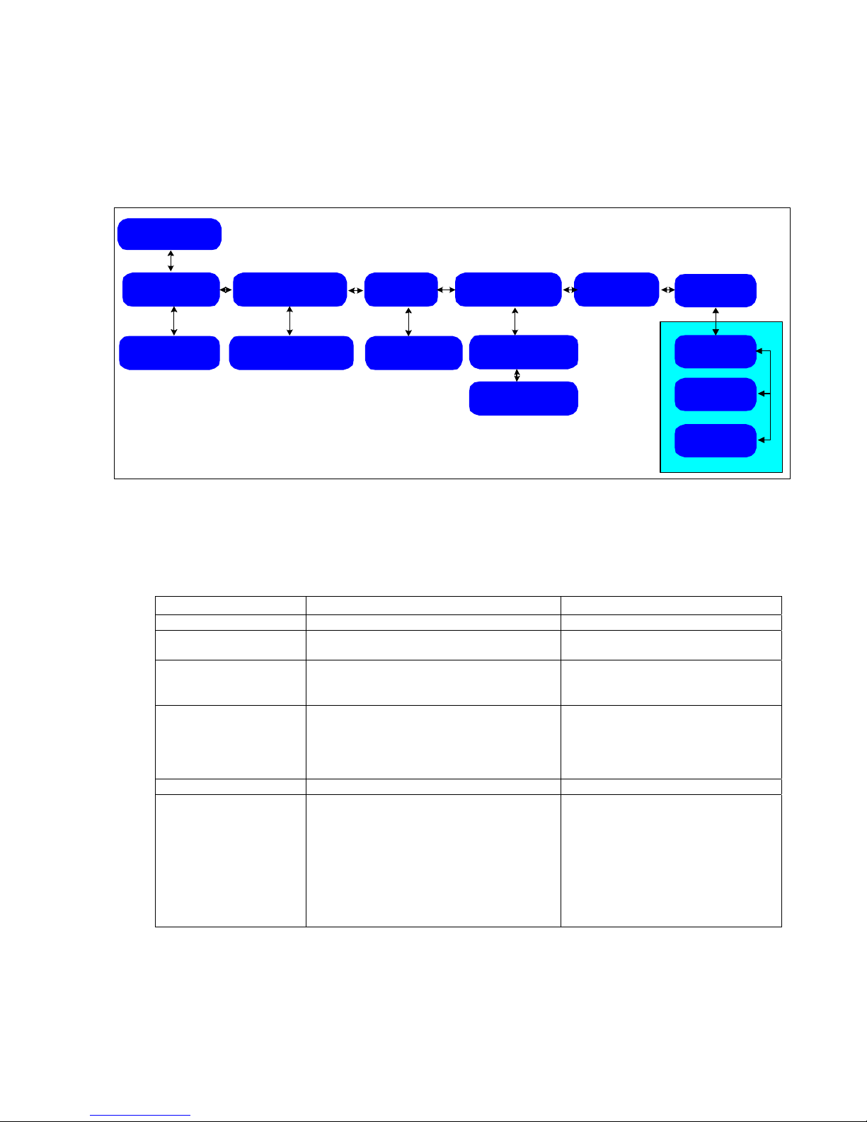
Utilities Screens
The Utilities screens include miscellaneous settings that apply to general DVB+ operation, as
described in Table 15.
Choose
Operation
Utilities
Select
Audio
Alignment
Audio Alignment
Off/On
Select
Output serial
data
Stop Head Data 0
Press CANCEL RTS
off
Figure 21 Utilities Screens
Table 15 Utilities Fields
Indication: Description: Notes:
Select Audio Alignment Turns on/off audio align feature
Select Output serial
data
Select Stat Logger Turns on/off stat logger Sends a line of status information to
Select SW Update
Monitor
Status
Checksum
Image
Select System Reboot Reboots the DVB+
Select Status Packet Allows you to determine a rate and to
Turns on/off output data to test the serial
port
Shows which of the 3 images from flash
memory ---BOOT, APP1, or APP2---are
currently being used at boot time
select an external IP address and output
port through which to send a UDP status
report packets.
Status packets report on signal strength,
Eb/No, demodulator error count, MPE
section error count, and carrier
lock/unlock.
Select
Stat
Logger
Stat Logger
off/1/2/5/10
Hz
Select
SW Update
Monitor
SW Update
Status:
Ready
Checksum Image
(NA) Boot
Select
System
Reboot
Select
Status
Packet
Select
Report Rate
Select
IP Address
Select
Port Number
Sends a test pattern to the serial
port
the RS-232 serial port at a regular
interval
Checksum is displayed only with
APP1 and APP2 images
Setting a rate of 0 seconds/packet
turns off the status packet feature.
Refer to the
Functional Overview for
a discussion of status monitoring
options.
MS4966 Rev 1.2 31
Page 38
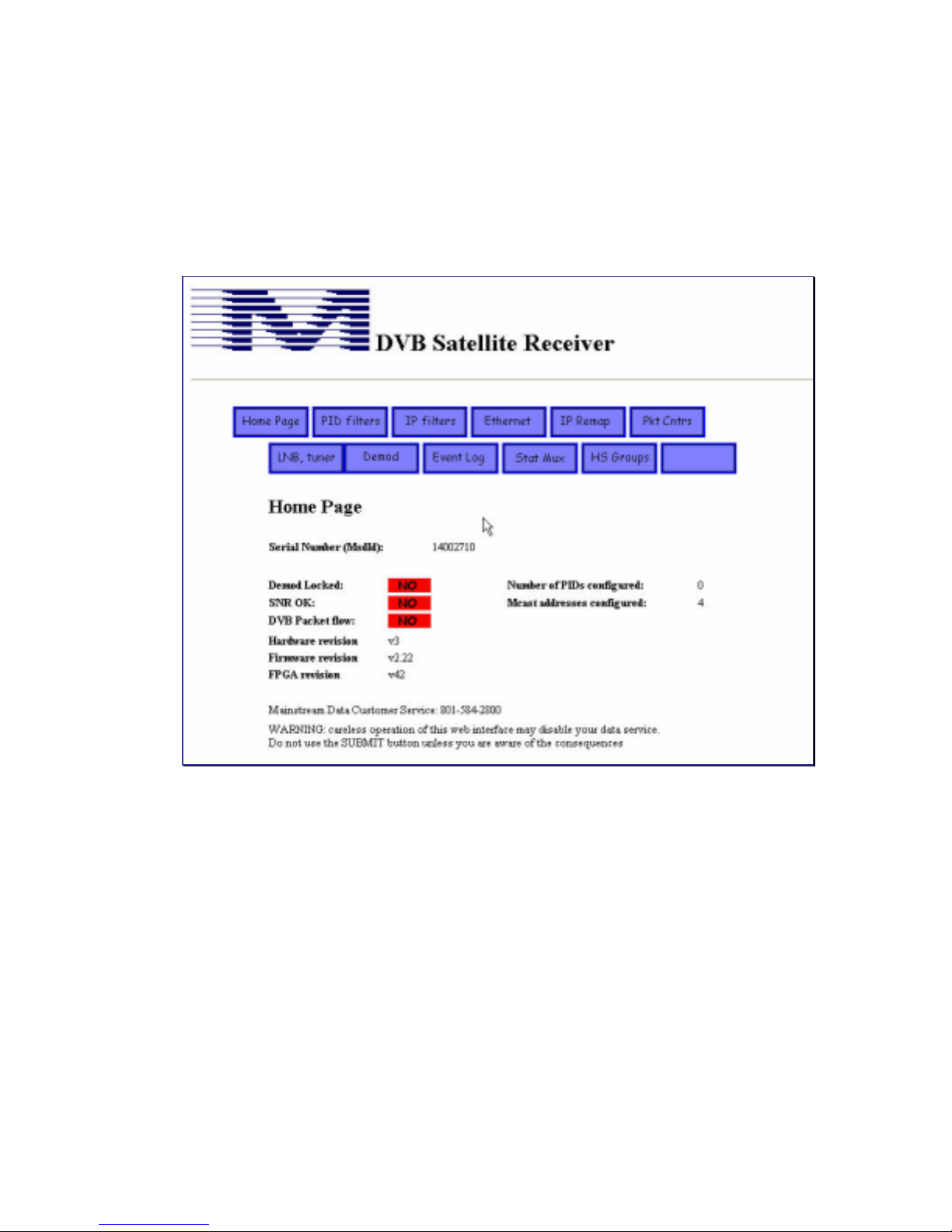
Using the Web Browser Interface
Most DVB+ configuration parameters can be viewed or changed from the Web page interface.
Although the menu structures of the front panel and Web interfaces are not identical, any
changes made to a variable through the Web interface are immediately visible on the LCD
panel, and vice versa.
Figure 22 Home Page of the DVB+ Web Interface
The receiver includes a Web server application that is accessed by setting up Windows to point
to the IP address of the DVB+ Aux Channel. As you click on a menu box to open a new page,
a snapshot is taken of the DVB+ variables associated with that screen image. These variables
are presented as a static display on the browser screen. To see if a counter is incrementing or to
observe new settings, you can refresh the page by re-clicking the blue page menu button.
Entering and Updating Values on the W eb Pages
New values that are entered on a Web page are submitted to the receiver by clicking the
SUBMIT button at the bottom of the page (or on some browsers by pressing ENTER on the
keyboard). If any submitted values are not valid a red error message appears at the bottom of
the page when that page is repainted. No updates are made to any variable on that page if you
have entered an erroneous value in any of the fields. For some fields, red error messages of
submitted invalid entries are displayed in the upper right corner of the screen.
32 MS4966 Rev 1.2
Page 39
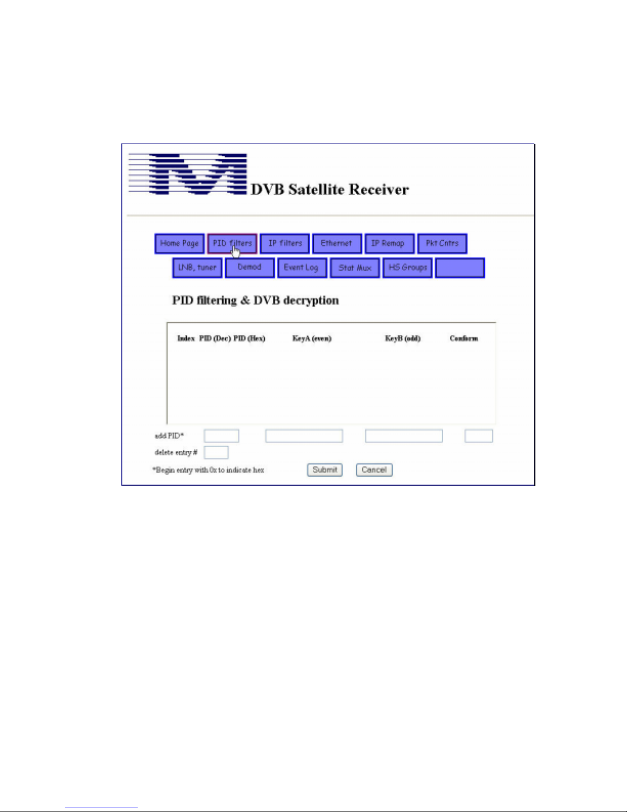
PID Filtering and DVB Decryption Page
In the Filtering page, you can view, add, or delete PIDs and IP multicast addresses that are
filtered for reception.
Figure 23 PID Filtering and DVB Decryption Web Page
You can enter PID values using either hex or decimal values. ( Both hex and decimal values
can also be seen within the View Setups LCD screen.) Enter encryption keys as 16-character
values. The Conformance bit entry is a “yes” or “no”.
Note: To specify no encryption exists leave the Key and Conform fields blanks. For example, if an existing
PID contains keys that you want to delete, “add” the same PID number, leave the Key and Conform
fields blank, and click on Submit.
The same process can be accomplished through the Specify Setups>IP Channel
Setups>Specify PID Table LCD screen.
MS4966 Rev 1.2 33
Page 40
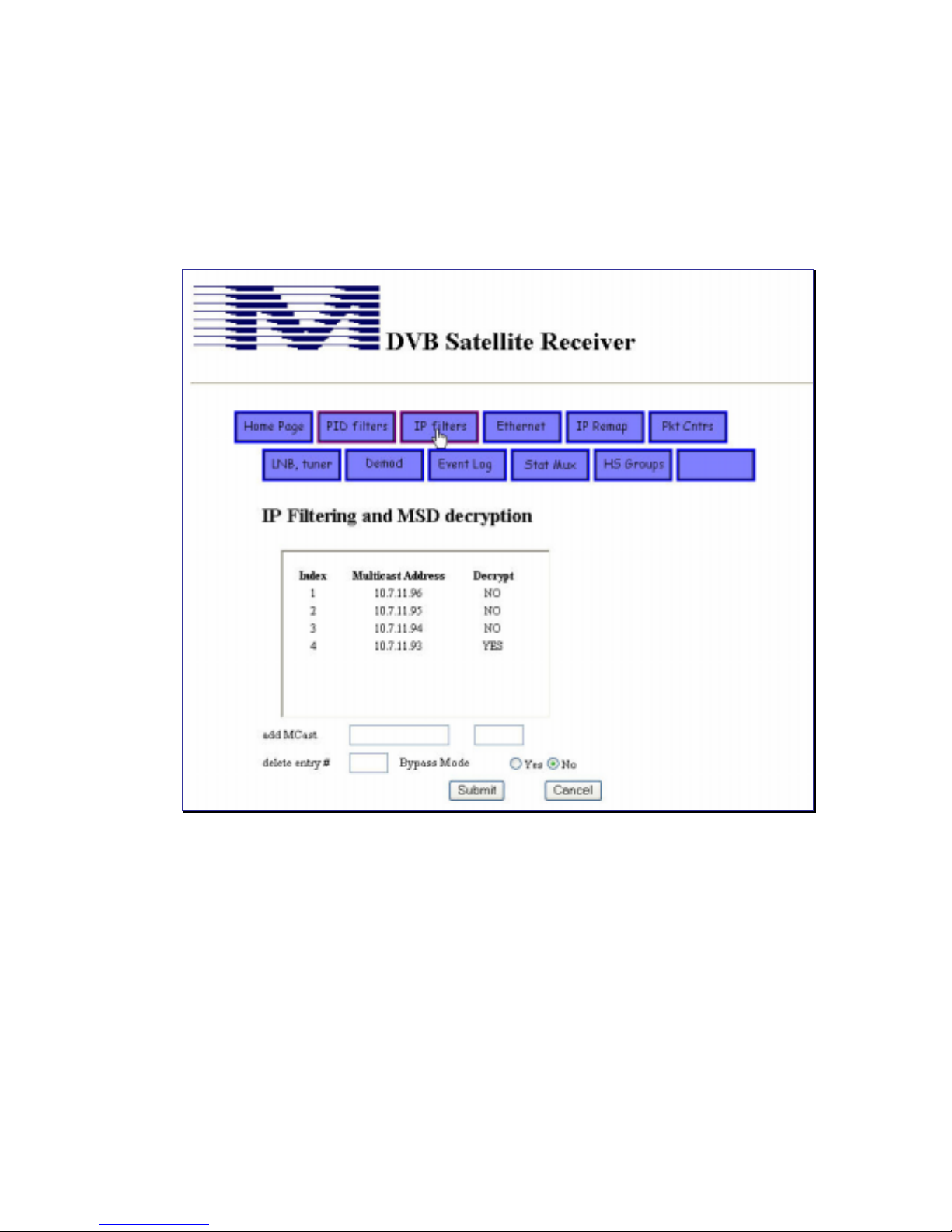
IP Filters
In the IP Filters page you can add or delete multicast addresses selected for filtering and
determine for each whether MSD decryption should be applied.
If you are adding an address, enter it in the first box adjacent to add Mcast. In the next box,
type in either 0, NO, or no for no decryption; 1, YES, or yes for decryption.
Figure 24 IP Filtering and MSD Decryption Web Page
34 MS4966 Rev 1.2
Page 41
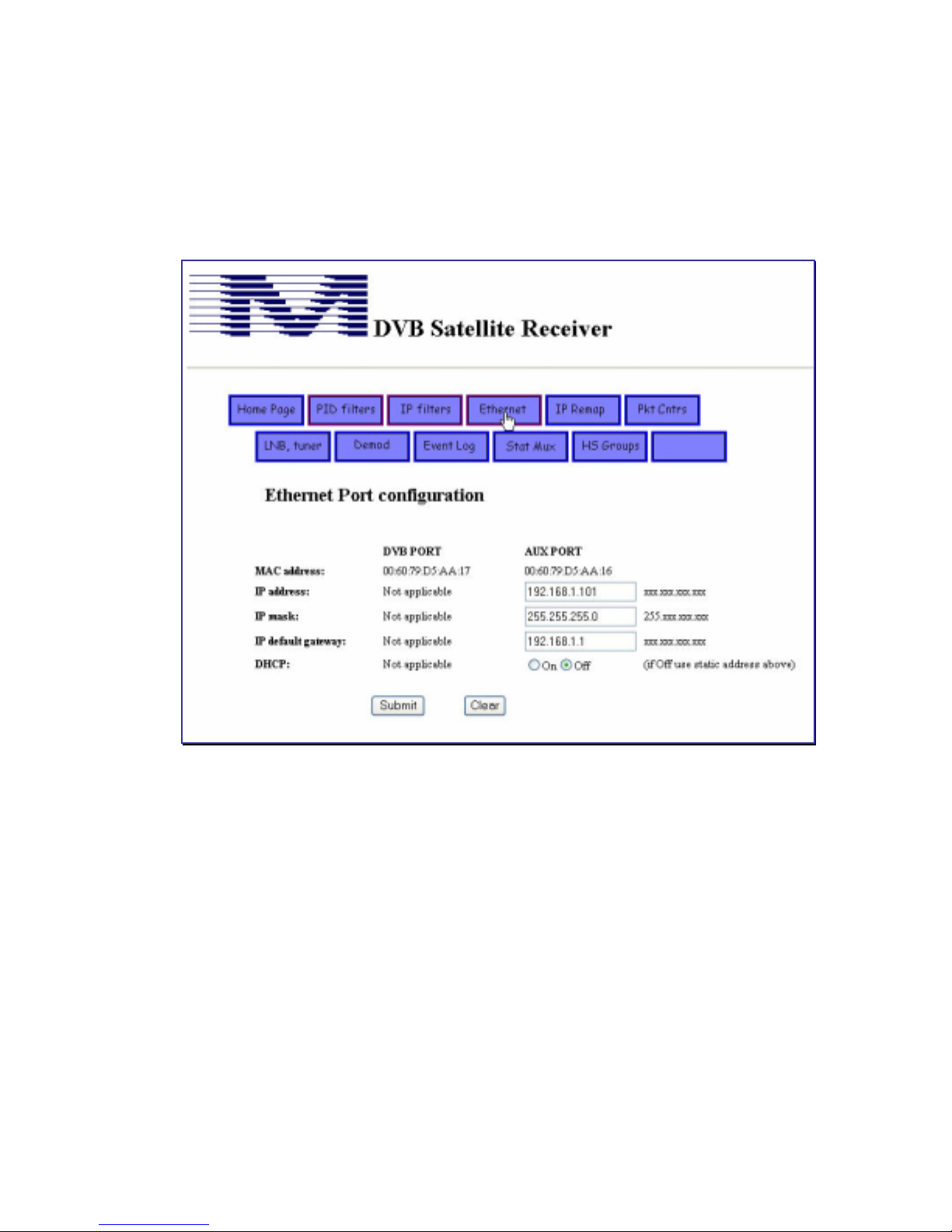
Ethernet Port Configuration Screen
If you change any of the Aux port Network Parameters, such as the receiver IP address, you
need to reboot the DVB+ for those changes to take effect. If you need to make several changes
to these Network Parameters it is more expedient to make all the changes first, and then reboot
once.
Figure 25 Ethernet Web Page
DVB Port and Aux Port correspond to the “DVB Channel” and “Aux Channel” on the
receiver.
MS4966 Rev 1.2 35
Page 42
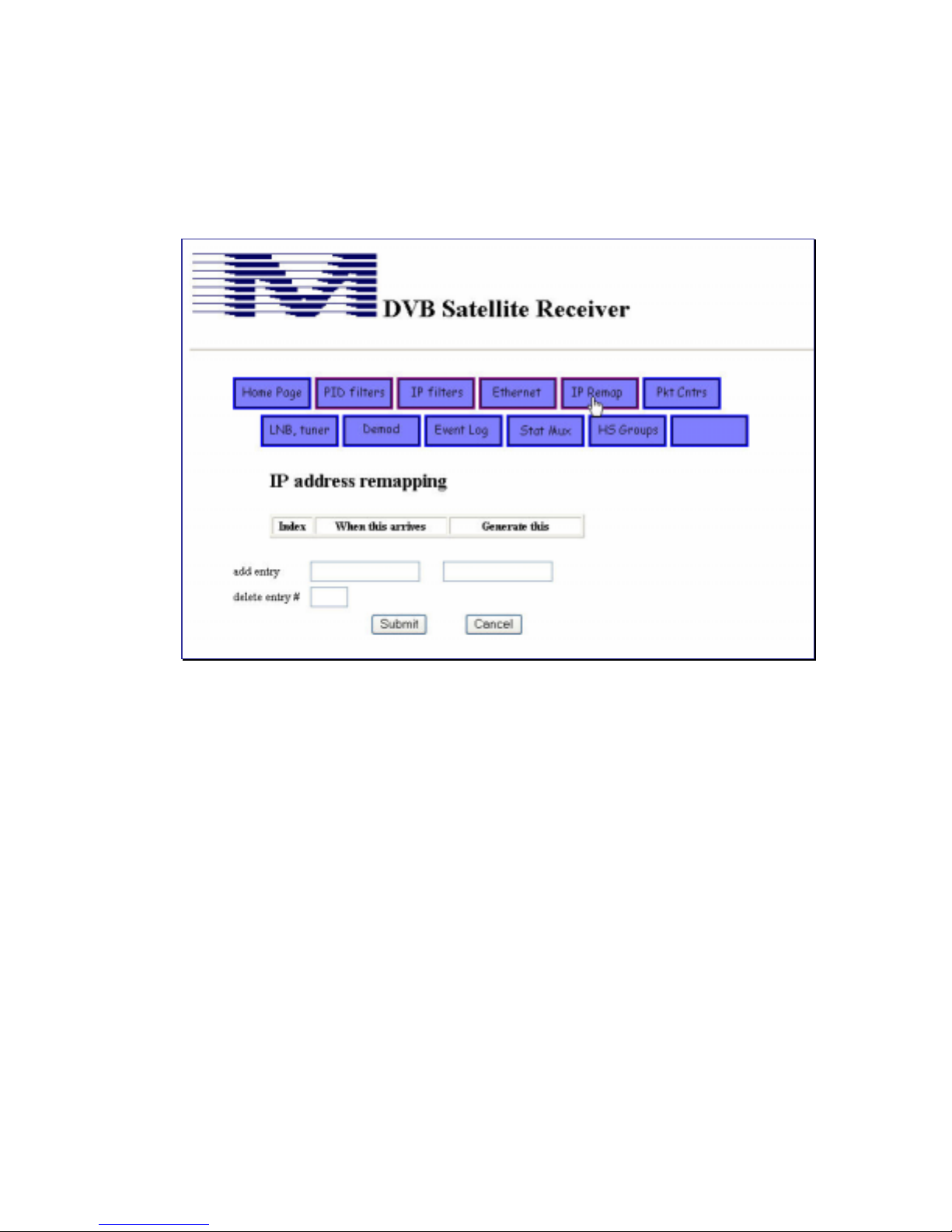
IP Remap W eb Page
IP remapping, sometimes called Network Address Translation (NAT), is useful in situations
where existing applications running on the local LAN are already using a specific IP address.
You can remap an IP address on the DVB+ to prevent addressing conflicts.
Figure 26 IP Remap Web Page
The IP remapping applies only to the DVB channel and not to the Aux channel.
36 MS4966 Rev 1.2
Page 43
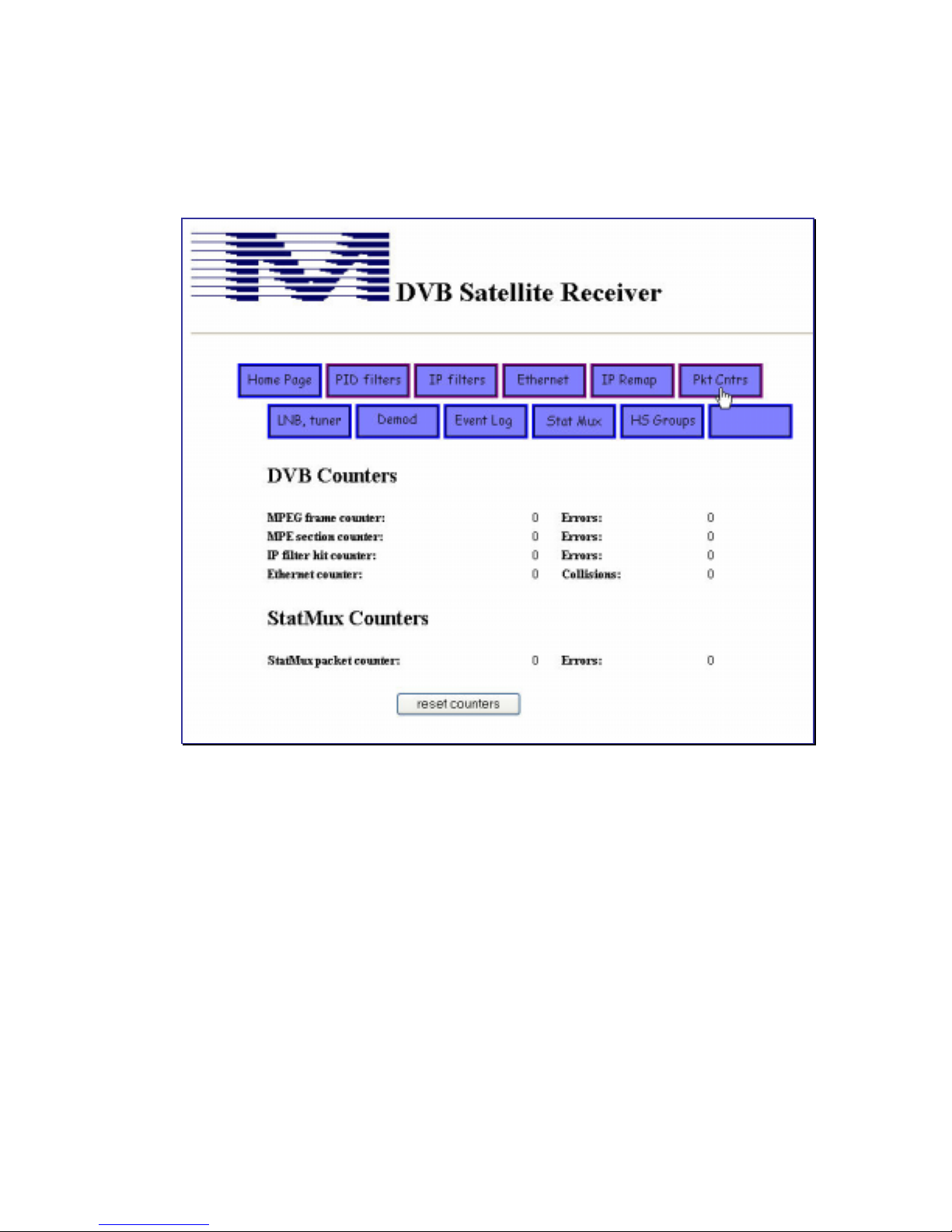
Packet Counters Web Page
The Packet Counters page summarizes both stat mux and multicast packets received, along with
error counts.
Figure 27 Packet Counters Web Page
Under DVB Counters in Figure 27, the IP filter hit counter reports the number of IP filter
matches. It does not increment when the DVB+ is in Bypass Mode because address matches
are not being checked in that mode.
The Ethernet counter reflects output activity on the DVB+ 100baseT connector. It can
increment even when the IP filter hit counter does not increment.
MS4966 Rev 1.2 37
Page 44
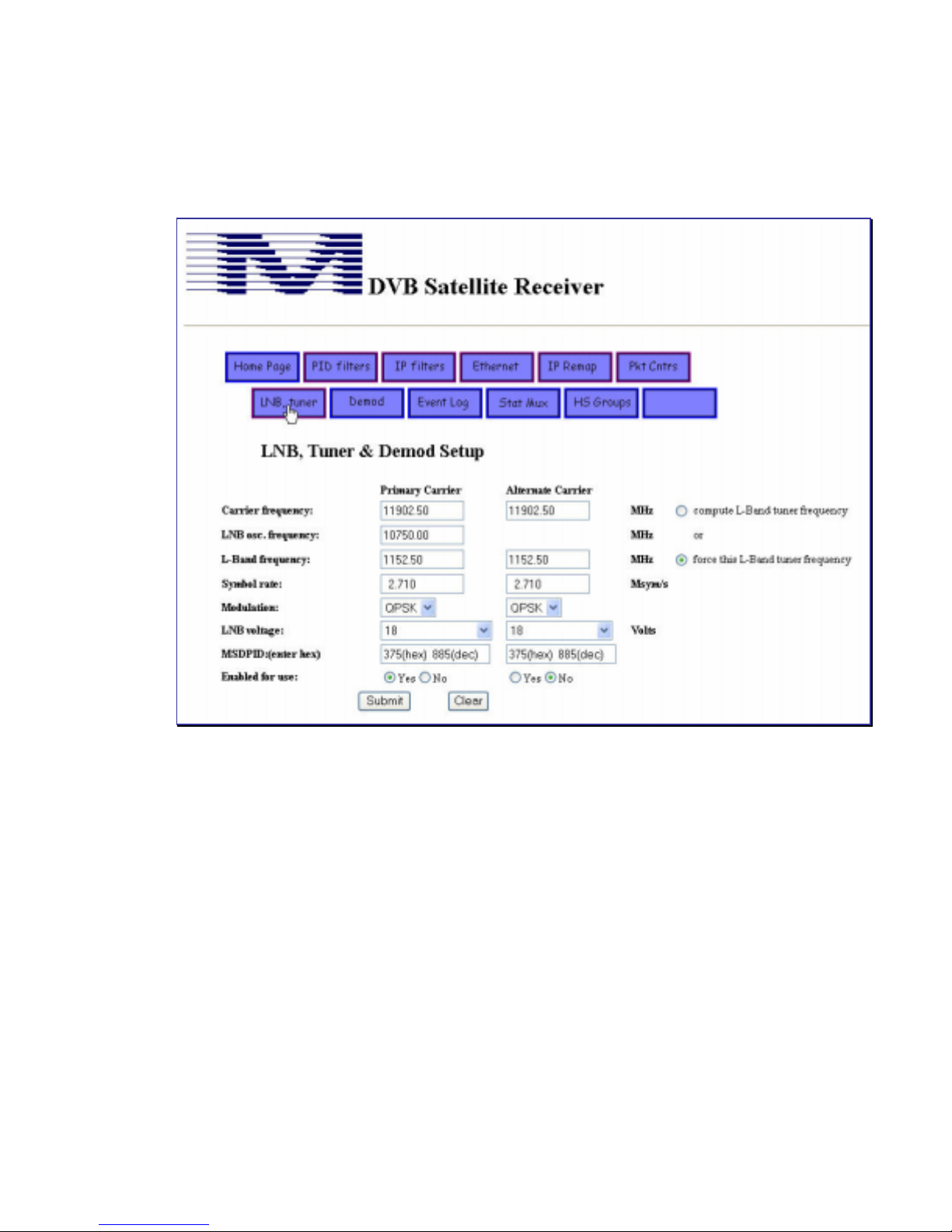
LNB and Tuner Web Page
The LNB and Tuner page allows you to view and modify settings for the LNB voltage and the
tuner and demodulator attributes.
Figure 28 LNB and Tuner Web Page
The DVB+ tunes to the L-band frequency. The carrier frequency and the LNB oscillator
frequency fields are provided mainly for the installer’s convenience who is aware of the
applicable equation: L-Band frequency = carrier frequency – LNB oscillator frequency.
This page enables you to either force the given L-Band tuner frequency based on the entry in
the L-Band frequency field or to require the receiver to compute the L-Band frequency based
on the entry in the Carrier frequency field. This flexibility may be useful depending on the type
of information provided at installation time.
38 MS4966 Rev 1.2
Page 45
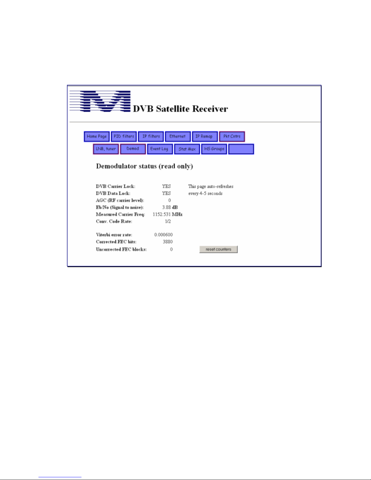
Demodulator Web Page
The Demodulator page is a read-only status page of current signal information, including lock
status, signal quality, and error counters. The page is automatically refreshed every 4-5 seconds.
Figure 29 Demodulator Status Web Page
MS4966 Rev 1.2 39
Page 46
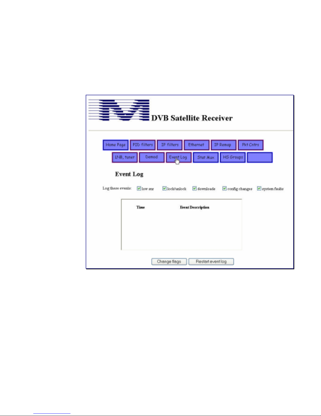
Event Log Web Page
The event log timestamps occurrences of designated system activities and functions. As a
diagnostic tool the event log is useful for verifying that signal quality has dropped below (or
increased above) a threshold, that the demodulator has unlocked (or relocked), that downloads
have occurred, that various settings have been changed locally, or that various system faults
have been detected..
Figure 30 Event Log Web Page
The event log functions differently depending on DVB+ release level. In early releases the
event log stores up to 100 events in RAM; the list is lost during power cycling or rebooting. In
later releases, the event log is stored in non-volatile memory. That list is maintained throughout
subsequent reboots or power cycling.
To change logged events, check or uncheck the category boxes, then click on the Change
Flags button. To erase old events and restart the log, click on the Restart Event Log button.
40 MS4966 Rev 1.2
Page 47
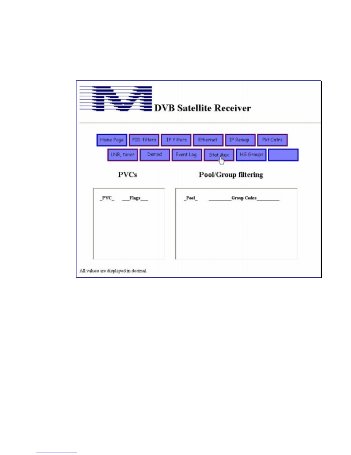
Stat Mux W eb Page
The Stat Mux page displays the pool PVCs and groups designated for reception on the stat mux
channel.
Figure 31 Stat Mux Web Page
MS4966 Rev 1.2 41
Page 48
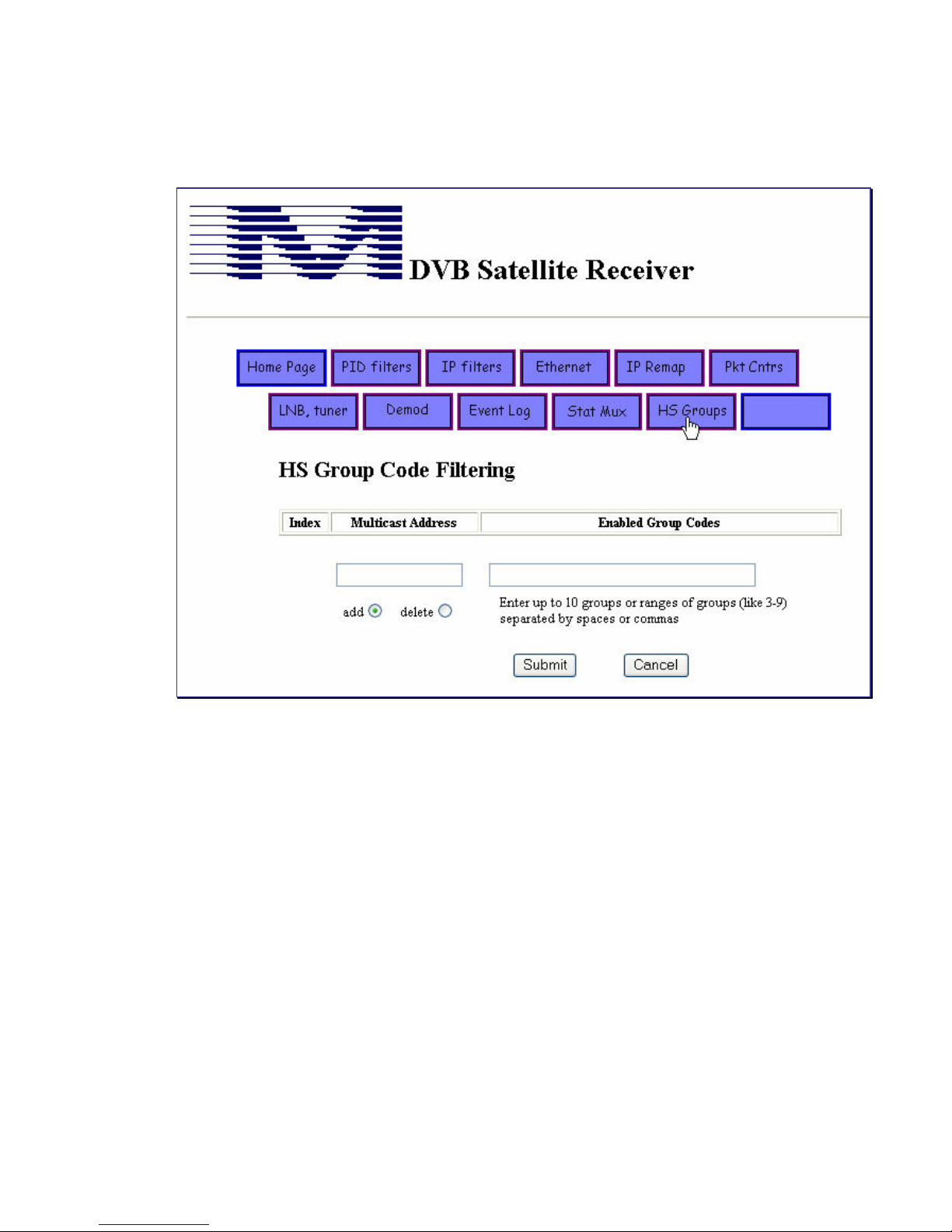
HS Groups Web Page
The High Speed Groups page allows you to add or delete pools and groups.
Figure 32 High Speed Group Code Filtering Web Page
Group codes range from 0 to 255. For example, an allowable group code entry that includes a
range would be 1,23-29,69,216-221,254.
42 MS4966 Rev 1.2
Page 49

Functional Overview
This section contains background information on data flow through the network and on the
functionality of the DVB+ Satellite Receiver.
Network Overview
The DVB+ Satellite Receiver provides data out by extracting IP multicast packets from MPE
sections and passing them out the Ethernet port labeled on the receiver as DVB Channel. The
unit extracts IP multicast packets from MPE sections based on the specified Program
Identification Descriptions (PIDs) and multicast addresses. In addition, the DVB+ can pass
output data through a standard serial port.
Network Components
The network comprises the following main areas:
• Access Network
The access network includes various means by which data arrives at the NOC from remote
sites over wide area networks, as well as through local PCs.
• Network Operations Center (NOC)
The NOC gathers and processes incoming data, uplinks data directly to a satellite or
transmits data to another site for uplinking, and provides network management services.
• Satellite
Channel space is leased on satellites by your network provider.
• DVB+
The DVB+ receives and processes the incoming data from the satellite downlink. It passes
the data to its attached output devices, such as local servers, an auxiliary monitoring PC, or a
LAN hub.
The Network Operations Center: Input and Output
Input to the NOC consists of data feeds arriving through the access network from remote or
local computers. Some of this data is processed through a statistical multiplexer (stat mux), and
some is sent unmodified as multicast packets. The multicast streams sent over satellite typically
include high-speed data streams in proprietary formats generated by the data originator.
The stat mux data is assembled into a series of packets. The packets contain information about
the data, such as message length, source, specific output destination, encryption or compression
keys, as well as the data itself.
The stat mux data, control channel information, and other data passing directly from the access
network is aggregated into a single DVB data stream and converted to a digital signal. This
signal is either directly modulated and uplinked to a satellite from the NOC or is transmitted to
another site for modulating and uplinking.
MS4966 Rev 1.2 43
Page 50

The DVB+ Satellite Receiver
The DVB+ receives data input from the satellite dish. The downlinked data stream is amplified
and shifted to a lower frequency by the LNB on the dish and passed through the coaxial cable
to the DVB+. The receiver demodulates the data and applies error-correction. Data is then
routed to the FPGA (Field Programmable Gate Array) for further processing. The FPGA
reconstitutes the original multicast packets. For data for which no further processing is
required, the data is routed directly from the FPGA to the DVB Channel Ethernet port. The
stat mux data is routed to the processor in the DVB+ for additional processing.
The processor handles the statistical demultiplexer channel, which includes a control channel.
The control channel is created by the Network Operations Center. The control channel is used
to send configuration information to the receiver. This configuration information specifies
which PIDs and multicast addresses the receiver is allowed to receive, which pools and groups
are allowed on the stat mux channel, and other parameters. Additionally, the stat mux channel
may contain data which is destined for the serial port on the receiver. The primary use of the
serial port data is to support legacy applications which have used a Mainstream Data IDR.
44 MS4966 Rev 1.2
Page 51
DVB+ Satellite Receiver
Input
L-Band
LCD
PIC Processor
1.5K RAM
32K Flash
256 EEPROM
RF Tuner &
Zero-IF Digital
Demodulator
User Interface
Keypad
I2C Interface
DVB
Data
Stream
ARM processor
16M RAM
8M Flash
8K EEPROM
FPGA
256K RAM
Field upgradeable
Buzzer
Control Channel PID
& Filtered Data PID
Filtered
Data Stream
Output
Web page for
Configuring
100base-T
Ethernet
Async Serial
Output
Multicast
10/100base-T
Ethernet
Figure 33 Functional Overview of DVB+
An L-Band satellite tuner subsystem in the DVB+ accepts signals from a roof-mounted dish
and low noise block converter (LNB) via a coax cable. The DVB+ provides power through the
coax for this LNB, as well as any in-line amplifiers. One of two voltages, 14 volts or 18 volts
can be sent up the coax cable. This allows for LNBs that use incoming voltage to switch
polarity, usually “high band / low-band”, though many LNBs have no such feature and will
work equally well on 14 or 18 volts. The LNB voltage can have a 22 kHz tone (0.5 v p-p) added
to the DC voltage for use with LNBs that switch oscillator frequency based on the presence of
the additional tone. The LNB voltage can also be turned off. LNB voltage and tone settings can
be selected via the LCD/keypad interface, or Web page interface, and by download. The LNB
power supply is immune from “back-power” (a higher voltage present on the LNB coax than is
being generated internally).
Daughter Card
Audio
Video
Non-volatile storage
SmartCard
Analog or
Digital Audio,
Video, or
Data Outputs
MS4966 Rev 1.2 45
Page 52

It is common for a satellite service to have a backup carrier that will be used in the event the
primary carrier fails. The DVB+ has the means to store two settings for carrier parameters
(MAIN and ALT), and if configured properly, checks for a valid carrier at the alternate
frequency if the primary carrier becomes unavailable. A specific RF channel is defined by six
parameters:
• L-Band frequency
• Baud rate
• Modulation type
• Control Channel PID
• LNB voltage
• 22kHz tone
Thus a backup (ALT) carrier need not be the same baud rate, or even the same polarity, as the
primary carrier. If no alternate carrier is available its settings can be disabled. If both RF
channels are enabled the receiver will check both, toggling back and forth, until a lock is
obtained. That channel is then marked as the “known good” channel. All subsequent reboots
will cause the receiver to check the “known good” channel first, at least until the receiver is
forced into hunting for a valid carrier again.
The tuner can acquire satellite signals that are slightly off frequency thus accommodating LNBs
with DRO-type oscillators. The acquisition range of the tuner has been set for +/- 2 MHz.
Once locked, the tuner can track carrier frequency variations up to +/- 2 MHz from the desired
frequency. When locked the carrier frequency can be displayed on the LCD display or
Demodulator Web page.
Once locked the demodulator chip provides an estimate of the carrier Eb/No. This is displayed
on the LCD display and Tuner Web page. This field is the most sensitive indication of optimum
dish alignment and is preferred to the AGC because the AGC value will stay constant over a
wide range of LNB polarization settings, while the Eb/No will change dramatically for any
small changes in polarization, dish azimuth, or elevation. Eb/No values below 5 will usually
indicate the link performance will be poor as small disturbances to the signal will cause the
Eb/No to drop below the threshold required for error-free performance.
FPGA: Processing Sequence
Figure 33 includes a block representing the Field Programmable Gate Array processing.
MPEG2 frames from the Tuner/Demodulator subassembly are passed to the FPGA where the
following sequence (a pipeline) of operations is performed:
Bad frame filter
MPEG frames that are uncorrectable by the Reed-Solomon error corrector are discarded.
PID filtering
The PID value of each incoming frame is checked against each of the 32 possible entries in the
PID filter table. If there is a match with any entry in the table, the frame is kept; otherwise, the
frame is discarded. In a typical installation dozens of PID streams may be present on a DVB
carrier but only a few are desired by the user.
46 MS4966 Rev 1.2
Page 53

DVB Decryption
Each PID stream can be decrypted by the DVB decryption process. Feeds that are not DVB
encrypted are unaffected by the DVB decryptor. Decryption requires the proper key values and
proper setting of the conformance bit, each of which can be downloaded or entered from the
Web page or LCD display, unless such access has been denied by the operator.
Section Depacker: Each PID stream on a DVB carrier may contain a different type of
data including video, audio, or non-IP data feeds. Such feeds cannot be decoded by the DVB+
and are discarded. PIDs that conform to the MPE Section format and contain IP packets are
kept and decoded. The DVB+ can decode PID feeds that are Section-packed or non-Sectionpacked, or any combination thereof.
IP datagram extraction
Each valid MPE section is parsed to extract the IP packet that it contains. If the IP packet is
valid and contains a UDP or multicast payload, it is kept and passed to the IP address filter,
otherwise discarded.
IP filtering
The destination IP address of each valid IP packet is checked against each of the 32 possible IP
address table entries. If there is match with any of the table entries the packet is kept; otherwise,
it is discarded. The source IP address is not checked. A single PID may contain multiple IP
address streams.
MSD IP decryption
Surviving IP packets may need to have IP-layer MSD encryption removed. Each IP address
table entry can have MSD IP decryption turned on or off.
High Speed Group Codes
IP packets are next subjected to the High Speed Group Code filter. If the destination IP
address in the packet matches the IP address setting in the filter, the packet is assumed to
contain additional group code information that was inserted before being transmitted. If no
match exists, the packet is passed forward untouched. If group codes are present, the 32 byte
group code mask in the packet is checked against the 32 byte mask in the filter. A match at any
bit position will cause the packet to be accepted, others discarded. Accepted packets are
reformatted to remove the 32 byte group code mask thereby returning it to its original format.
This type of filtering is not possible with IP addressing alone, as each message can be tagged
with multiple group codes.
IP address remapping
The destination IP address of each packet is checked against each of the four destination
addresses in the remapping table. If any match is found the destination address in the packet is
replaced with the new destination address found in the table. If no match is found the packet is
passed forward untouched. This is useful when the IP multicast address of a satellite data feed
conflicts with an IP multicast address service already being used in that LAN environment.
MS4966 Rev 1.2 47
Page 54

Ethernet frame generation
IP packets are turned into Ethernet frames by encapsulating the IP packet with 802.3 Ethernet
frame information fields including a source MAC address (which is the address of the DVB
port of the DVB+ receiver), a destination MAC address which is derived from the IP
destination address as per the IP Multicast standards, and a valid checksum. Frames are then
queued for output to the DVB Ethernet port. A buffer in the FPGA allows for several Ethernet
frames to be held while the Ethernet wire is being used by other senders.
Error Correction
The Viterbi decoder is auto-configuring; thus it is not necessary for the user to select a desired
code rate. The code rate that is discovered during carrier acquisition is reported on the LCD
display and Tuner Web page.
The Reed-Solomon FEC function can remove errors which are left behind by the Viterbi
decoder. Each Reed-Solomon block can correct a certain number of bad bytes within an
MPEG frame (there is one Reed-Solomon FEC block in each MPEG frame). When the
number of bad bytes exceeds the capability of the Reed-Solomon code the algorithm fails to
correct any of them and passes the corrupted block forward, but flagged to indicate that it
contains an unknown number of damaged bytes. Counts are kept of the number of bits that
have been corrected, as well as the number of uncorrectable blocks. These counters are
available on the LCD display and on the Demodulator status Web page. Another LCD field,
CBitRate, displays a real time calculation of the number of bits corrected by Reed-Solomon
divided by the total number of bits received (since the counters were cleared). This equals the
pre-Reed-Solomon bit error rate (assuming there are no uncorrectable blocks during the test),
which is useful for demodulator performance measurements.
Status Monitoring
The DVB+ includes three mechanisms for reporting and viewing various types of receiver and
activity status. The Stat Logger LCD screen, under the Utilities menu, is used to send a line
of status information through the RS-232 serial port. This information can be viewed through a
PC running the Hyperterminal program.
The Status Packet LCD screen, also within the Utilities menu, outputs signal strength,
Eb/No, demodulator error counts, MPE section error counts, and carrier lock/unlock data as
UDP packets in XML format.
The third status monitoring mechanism is through the Web page interface. Signal fluctuations,
carrier lock/unlock data, downloads, local configuration changes, and system faults are captured
and timestamped within the page.
48 MS4966 Rev 1.2
Page 55

Appendix A Technical Specifications
RECEIVER L-BAND INPUT
Input Frequency: 950 - 2150 MHz
Input RF Level: - 65 dBm to -25 dBm
RF Bandpass Filtering: 2 - 40 MHz Data processor : Programmable Gate
Carrier Tuning: 1 MHz steps PID Extraction: 32 PID filters + 1 for stat
RF Architecture: Zero-IF DVB decryption: Dual keys on each PID
Connector: F-type
LNB INTERFACE
Output Frequency: 950 - 2150 MHz IP multicast filtering: 32 IP address filters
Local Oscillator
required:
Stability +/- 150 kHz to
Coax DC Voltage: 0v,14V, 18VDC
Maximum Current: 400 ma (auto-recovery)
DiSEqC: 22 KHz tone on/off
RF CHANNEL DECODING
Bit rates: 2Mbps to 60Mbps Input : Carried on a PID
Channel Bandwidth: 1.4 x symbol rate Format: IP multicast packets
Demodulation: QPSK (DVB-Compliant) Packet protection: 16 bit CRC
Error Correction: 1/2 to 7/8 rate Viterbi Decryption: MSD decryption
Reed-Solomon (188/204) Decompression: MSD session or
LNB Drift Tracking: Up to +/- 2 MHz Output: RS-232 on Serial 1 (DBBER vs EbNo
performance:
OUTPUT PORTS
Electrical Interfaces: RS-232 seria l async Buffering: 512 KB
Ethernet (10/100BaseT)
Connectors: DB-9 Flow control: RTS, Xon/Xoff
RJ-45 (2)
Asynch Rates: up to 115,200 bps
Low-phase noise DRO MSD IP decryption: MSD proprietary on
500kHz
(selectable)
within DVB-S specs
(0.75 dB from theory)
Section depacking: MPE compliant
Section protocol: DSMCC private
Group code filtering: 1 pool with 256 groups
IP address remapping: Up to 4 IP addresses
Session filtering: By unit, PVCs (up to 10),
DATA DECODING for DVB PORT
sections, with UDP over
each IP address filter
STAT MUX
containing MSD protocol
TVCs (up to 32 pools
each with up to 256
Array
mux
filter, per DVB
specifications
IPv4 payload
packets
Huffman decoding
9)
groups)
FRONT PANEL LCD KEYPAD
LCD Display: 2 x 20 characters
Keypad: 4 rubber button
LEDs: 4 blue
MS4966 Rev 1.2 49
Page 56

SETTING AND VIEWING PARAMETERS
Parameter storage: EEPROM (non-volatile) Power Supply: External desktop module
Frequency and
modulation:
PID and IP multicast: LCD, HTML, download Frequency: 50 to 60 Hz (int’l IEC
Status reports: via LCD and HTML Input Po wer: less than 30 watts
Parameters monitored: Viterbi, R-S error rates,
MECHANICAL
Size: 9”L x 10”W x 1.75”H
Weight: 4.0 lbs (1.8 kg)
Operating
Temperature:
Humidity: 0 - 90% non-condensing
Shipper: cardboard, foam inserts
LCD and HTML Input Voltage: 100 to 240V (int’l IEC
AGC, Eb/No, packet
counts, locks, carrier
frequency
Output Voltage: 5VDC, 24VDC
Safety Approvals: UL/CSA/CE
POWER
jack)
jack)
50 MS4966 Rev 1.2
Page 57

Glossary
access network
acquisition
AGC
aggregate data
stream
asynchronous
AUI
BPSK
the various routes by which data feeds originating in diverse locations come
into the network control center for uplinking to Mainstream Data networks
the process by which the demodulator adjusts frequency, phase, gain, and
code-word synchronization to match that of the incoming carrier and lock to
it.
Automatic Gain Control. Relative reading of signal strength.
The non-partitioned data uplinked from the network control center and
received in the DVB+. The aggregate data stream must be disassembled,
reordered, and usually processed before it can be output to an external
device.
also async. Data transmission mode that transmits one character at a time,
does not use a data clock, and must supply its own start and stop bits and its
own error detection pattern.
Attachment Unit Interface.
Binary Phase Shift Keying. A method of modulation in which zeroes and
ones are represented by two phases of the RF carrier signal which differ by
180 degrees.
CRC
codec
conformance
control channel
data feeds
decryption
demodulator
Cyclic Redundancy Check. An effective error detection technique
coder-decoder
as defined by the DVB industry standards, a mode associated with DVB
decryption of a PID stream. If conformance mode is enabled at the head-end
it must be enabled at the receiver for the decryptor to work.
also network control channel. Information sent by the network control
center to a receiver to control its configuration; not intended for output
processing.
Transmittal of information from an originating source or from the network
control center.
process of turning an encrypted data feed back into a clear-text feed. Data
feeds are encrypted during transmission to prevent piracy of information.
(See DVB decryption.)
The component in the DVB+ that converts an incoming RF signal to digital
data for further processing. Also chooses a specific satellite carrier.
MS4966 Rev 1.2 51
Page 58

downlink
download
DVB
DVB decryption
DVB-S
EEPROM
Ethernet
event log
FEC
An earth station that receives information from a satellite.
Control information transmitted from a network control center to a receiver
Digital Video Broadcasting. An international standard for transmission and
reception of MPEG signals.
feature of the DVB+ to perform decryption according to the DVB standards,
thus allowing access to certain PID streams.
Digital Video Broadcasting-Satellite. An international standard for
transmission and reception of MPEG signals via satellite.
Electronic Programmable Read-Only Memory.
A local area network (LAN) implementation.
a list of important events that have occurred within the DVB+ since the
receiver was last powered up, useful for diagnostics. The event list can be
viewed or cleared using the Event Log Web page.
Forward Error Correction.
head-end
high speed group
codes
IDR
keys
L-band
LCD
LNB
lock
The network control center, or the location that assembled and transmitted
the received data stream
a hardware function in the DVB+ to filter or pass news stories that are
tagged with a High Speed Group Code mask. Similar in concept to the
Pools/Groups feature of the Stat Mux.
Intelligent Data Receiver. A Mainstream Data product trademark.
Secret numbers that are required to decrypt a data feed. Usually the same
key is used at the transmission side to encrypt that feed.
Used to denote LNB output and DVB+ input frequency range, which is
between 950 MHz and 2150 MHz.
Liquid Crystal Display. Used as the mechanism displaying the front panel
screens.
Low Noise Block Converter. The device attached to the satellite dish that
extracts a set of satellite carriers, lowers their frequency to the L-Band
range, and amplifies the signal to an appropriate input level for the tuner.
proper carrier is located and is being received and demodulated.
logical receivers
52 MS4966 Rev 1.2
separate entities defined by software that function as distinct destinations for
incoming data.
Page 59

MPE
MPEG
NMS
network operations
center
Node
nonvolatile memory
Multi Protocol Encapsulation. An hardware-independent encapsulation
format used to packetize data being transmitted as MPEG datastreams.
Motion Picture Experts Group. An international standard for encoding and
sending video, audio, and ancillary data.
Network Management Services. A means of controlling and monitoring
operations at the network control center.
NOC. The “head-end” or hub where data feeding in from multiple
origination points is assembled, statistically-multiplexed, time-division
multiplexed, modulated, and prepared for uplinking to a satellite. The NOC
would typically notify receiver sites of network changes required at their
site and then download those changes.
mode of operation using a transport protocol that enables packets to be
individually read, error-checked, reassembled, and output as integral blocks
of information. The output blocks are packets of type “extract protocol.”
Used only with Mainstream Data proprietary software.
Portion of the memory that retains information even when power is turned
off; settings stored in nonvolatile memory do not have to be reissued after a
power interruption unless a change to an operating parameter is required.
PAD
PID
PSK
PVC
packet
propagation delay
QPSK
Packet Assembler-Disassembler . A mode of operation using a transport
protocol that outputs data in the same format and order in which it was
received at the NOC.
Program Identifier. Numeric tag in each DVB MPEG2 frame that associates
that frame with a specific information stream. A receiver may pass certain
PIDs and filter out others.
Phase Shift Keying. Form of modulation used to impress information onto
an RF carrier for transmission from one location to another
Permanent Virtual Circuit. A dedicated communications circuit that allows
for continuous data transmission. Contrast with TVC, that requires each
transmission session to be opened, then closed when the session ends.
Contains data and processing information such as the source of the data, the
length of the message, and its destination. Packets must be statistically
demultiplexed in the DVB+ before the message can be processed and
output.
the delay from the time a signal is sent until it is received.
Quadrature Phase Shift Keying. Phase shift keying in which four discrete
phases of the RF carrier are used, each differing by 90 degrees from the
next. Each set of four phases represent two consecutive bits of the data
stream.
MS4966 Rev 1.2 53
Page 60

Reed-Solomon
codec
RS-232
RF
SCPC
session
statistical
multiplexer
block-oriented coder/decoder hardware that is applied on top of standard
Viterbi coding to correct most data errors that are not corrected by Viterbi
devcoder; significantly reducing the bit error rate. (Standard in DVB+
systems)
an Electronic Industries Association (EIA) standard for low-speed,
asynchronous and synchronous transmission
Radio Frequency
Single Channel Per Carrier. A carrier having only one channel, contrasted
to a DVB multiplexed carrier, which contains several channels or feeds.
A communication circuit selected for use by the DVB+ when configured for
stat demux operation. Active sessions in the screen display describe current
stat mux activity
also stat mux. A technique of time-sharing on a data stream that allows for
more efficient usage of the carrying capacity. To accomplish this, additional
information must be added to each data packet to identify its characteristics
and its routing. Extracting this information at the receiver end requires
analogous demultiplexing. In the DVB+, the function that occurs is
demultiplexing, or stat demux
subscription
services
superscreen
symbol rate
synchronous
TVC
uplink
upload
the news or information products that end users pay to receive
One of the primary Show IDR Status screens that identifies current stat
mux activity in the receiver, such as incoming data packets and
miscellaneous error correction reports. These superscreen indications are
relevant only to stat mux operation.
signal pulses that relate to number of bits of transmitted data
also sync. Data transmission mode that establishes a clocking mechanism
between sender and receiver to identify the data. Synchronous data is
typically transmitted in blocks, rather than the character-at-a-time method of
asynchronous transmission.
Temporary Virtual Circuit. A communication link established only for the
duration of the transmission. Contrast with PVC, which is an open,
dedicated circuit used for continuous transmission.
Transmitting data from an earth station to a satellite.
Transferring data from a computer to the DVB+. In Mainstream Data
operation, uploading usually refers to setting or modifying the configuration
parameters of an DVB+ at the factory.
54 MS4966 Rev 1.2
Page 61

volatile memory
Viterbi
Segment of processor memory that is lost when power is turned off or
interrupted. In the DVB+, certain commands or settings, such as those used
to perform a real-time function or enter a test mode, are temporarily stored
in volatile memory. (Configuration parameters are not volatile; they remain
in memory even if receiver power is turned off.)
a standard method of forward error correction decoding that is applied by
the DVB+ to all data received.
MS4966 Rev 1.2 55
Page 62

56 MS4966 Rev 1.2
Page 63

Index
Access network
defined, 43
AGC
installation, 6
Aux Channel
verifying installation, 7
Aux LAN
specify setups, 28
Aux LAN setup
view, 23
AUX LAN setups
DHCP, 23
BPSK, 22
Bypass mode
IP Channel setup, 20
specify IP Channel setup, 26
Cables, 4
Changing PID filters
Web page, 33
Changing settings, 9
front panel, 9
NOC download, 9
Web interface, 9
Customer support, 2
demodulating, 44
Demodulator status
read-only, 39
DHCP usage
specify AUX LAN setups, 28
Documentation
purpose, 2
Downloading from NOC
Customer service support, 6
DVB Channel
verifying installation, 7
DVB decryption
Web page, 33
DVB encryption keys
LCD screen, 26
DVB MAC address
IP Channel setup, 20
DVB+
functional overview, 43
DVB+ Features, 1
Eb/No
installation, 6
Entering and changing values, 11
Error-correction
method, 44
Event log
Web page, 40
Event Log Web Page
description, 48
Factory settings
reinstalling, 30
FPGA processing
DVB decryption, 47
high speed group codes, 47
IP filtering, 47
PID filtering, 46
FPGA processing sequence, 46
Front panel
figure, 9
overview of use, 9
Functional overview, 43
diagram, 45
Glossary, 51
High speed group codes
IP Channel setup, 20
High-speed groups
Web page, 42
IDR Channel
specify setups, 25
Indicators
described, 10
Installation
connecting cables, 4
network download, 6
procedures, 4
safety, 2
using Show Status LCD, 5
verifying data output, 7
verifying lock, 5
verifying signal strength, 6
Installing the DVB+
prerequisites, 3
IP address
Aux LAN setup, 23
IP Channel
specify setups, 26
MS4966 Rev 1.2 57
Page 64

view setups, 19
IP Channel setups
Bypass mode, 20
DVB MAC address, 20
high speed group codes, 20
IP remap table, 20
multicast table, 20
PID table, 20
IP packet counter
bypass mode, 16
IP packet counters
Ethernet counter, 37
IP remap table
IP Channel setup, 20
Keypad
entering values, 11
L-band
tuning to the set frequency, 38
LCD screen
described, 10
LCD screen variations, 13
LCD screens
using, 10
LNB
Web page, 38
LNB voltage
View Tuner setups, 22
Lock LED, 5
Locking on carrier, 5
MAC address
preconfiguration, 9
Main screens
described, 10
Maintaining equipment, 7
Menu topics
overview table, 11
Menu tree
top level, figure, 10
Modulation
QPSK or BPSK, 22
MSD identification
preconfiguration, 9
Multicast addresses
defined, 1
Multicast addressing
function, 44
Multicast table
IP Channel setup, 20
Navigating the LCD screens. See Using
the Keypads
Network Address Translation. See IP
Remap
Network components, 43
Network Operations Center
defined. See NOC
Network overview, 43
NOC
defined, 43
option bits, 13
Output Status Packet
Utilities screen, 31
Overview
DVB+ features, 1
multicast packets, 1
PIDs, defined, 1
Packet counters
IP filter hits, 37
Web page, 37
PGA processing
MPE section depacking, 47
PID filtering
described, 47
PID filters
Web page, 33
PID table
DVB encryption, 26
IP Channel setup, 20
reviewing or modifying, 26
PIDs
defined, 1
Pools and groups
Stat mux web page, 41
Prerequisites for installation, 3
Processor
function, 44
QPSK, 22
Rear Panel
figure, 4
Rebooting system
from Utilities screen, 31
Reed-Solomon, 48
Reinstall settings, 30
Remapping IP addresses
purpose, 36
through Web page, 36
Safety issues, 2
58 MS4966 Rev 1.2
Page 65

Screens
interpreting, 14
Show Status, 14
Serial 1
specify setups, 29
Serial 1 setups
baud rate, 24
data bits, 24
flow control, 24
parity, 24
stop bits, 24
Show status
superscreen, figure, 14
Show Status
IP Channel, 16
Show Status screens, 14
IDR Channel status, 14
tuner status, 17
Specify IDR Channel setup
Serial 1 attributes, 25
Specify setups
Aux LAN, 28
IP Channel, 26
tuner, 27
Specify Setups
IDR Channel, 25
Serial 1, 29
Stat logger
description, 48
Stat mux
Web page, 41
Stat mux data
defined, 43
Status packets
description, 48
Superscreen
use during installation, 7
technical specifications, 49
Testing serial port
Utilities screen, 31
Tuner
specify setups, 27
view setup, 22
Tuning
description of frequencies, 38
Using the keypads, 10
Utilities screens, 31
audio alignment, 31
software update monitor, 31
stat logger, 31
status packet, 31
test serial port, 31
Verifying data output
during installation, 7
View Setups
Aux LAN, 23
IP Channel, 19
Serial 1, 24
tuner, 21
View Setups screens
IDR Channel, 18
Viterbi, 48
Warranty, 2
Web interface
entering values, 32
Ethernet port configuration, 35
filtering page, 33
function, 32
homepage, 32
IP remap page, 36
overview, 32
Web page
changing DVB encryption keys, 33
changing PIDs, 33
demodulator status, 39
event log, 40
high-speed groups, 42
LNB, 38
packet counters, 37
PID filtering and DVB decryption, 33
stat mux, 41
tuner, 38
MS4966 Rev 1.2 59
 Loading...