

Page 1
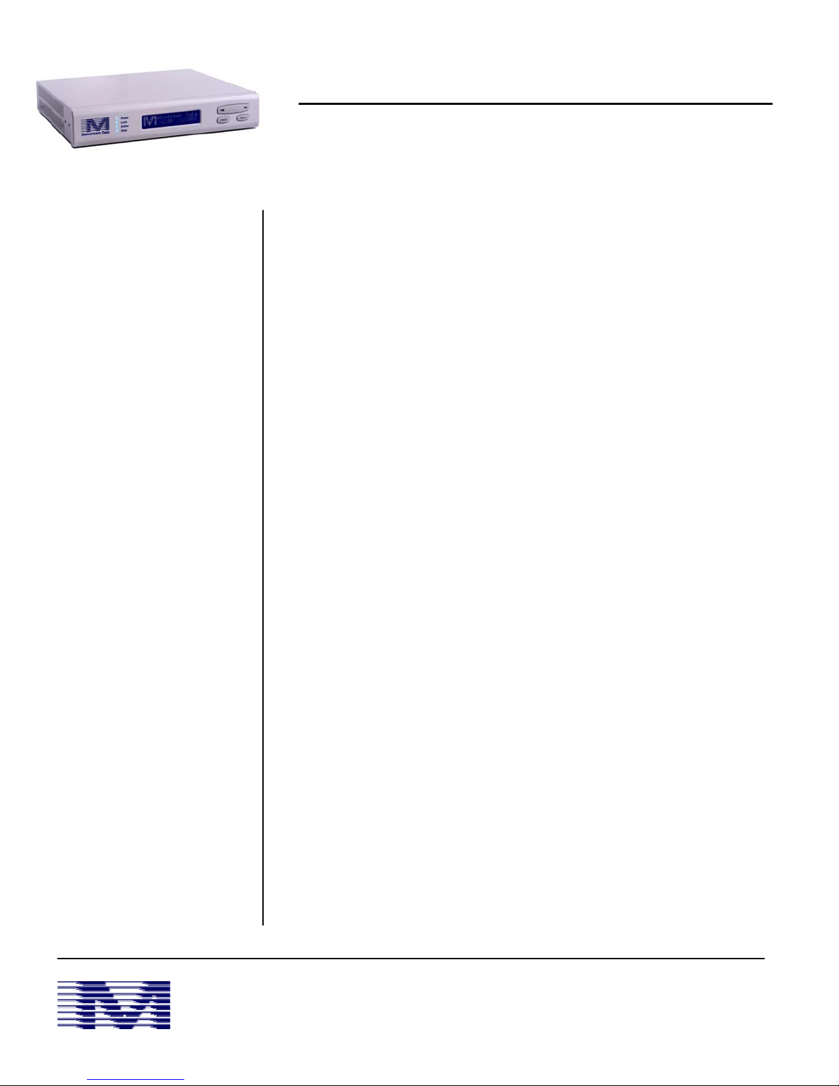
DVB+™ Satellite Receiver
Installation Guide for Certified Equipment Technicians
• Assemble and align
satellite dish
• Run coax from dish
to DVB+™ receiver
• Ground coax cable
• Attach coax to
DVB+™ via F
connector labeled
“RF INPUT”
• Connect CAT5
Ethernet cable to
DVB+™ via RJ-45
port labeled “DVB”
- or -
• Connect DB-9 data
cable to DVB+™ via
RS-232 serial port
• Attach external
power cord to
DVB+™ via “POWER
IN” connector
• Power on DVB+™
• Verify carrier lock
DVB+™ is a commercial quality, DVB-S compatible satellite receiver designed to
receive, demodulate, and process data streams on high-speed satellite carriers.
Installation should only be performed by technicians certified to install satellite
receive equipment.
Installers should assemble and align an approved satellite antenna (“dish”) and
attach RG-6 cable (“coax”) to the appropriate connectors on the dish. To prevent
electrical fire and minimize equipment damage due to lightning, the RF coax cable
shield must be connected to earth ground with #10 or heavier gauge solid copper
wire at the point of entry into the building.
Coax is then attached to the DVB+™ receiver via the F connector labeled "RF INPUT"
on the rear panel. The coax cable provides power to the LNB and carries the
950-2150 MHz RF signal from the LNB to the receiver. The RF input level for the
desired carrier should be between -65 dBm and –25 dBm. An RF in-line amplifier
must be used for cable runs of more than 100 feet.
Depending upon the installation, data is passed from the DVB+™ receiver via an
Ethernet or serial connection. For installations using Ethernet output, installers
connect CAT5 Ethernet cable from the 10/100Base-T port of a suitable switch,
router, or PC to the rear panel RJ-45 Ethernet port labeled “DVB”. When
connected properly, the LINK light on the connector will illuminate. Installers
should note that when connecting directly to a PC, an Ethernet crossover cable
must be used.
The other RJ-45 Ethernet connector, labeled “AUX” is for system maintenance and
some low-speed data services. This port should NOT be used for normal operation
unless specified by Mainstream Data.
For installations using the Serial connection alternative, installers connect a
shielded DB-9 data cable from the COM port of a PC to the rear panel RS-232 serial
port. Refer to the pinout diagram on back for detail on connector pinouts. To
prevent unwanted RF radiation from the data cables, only cables with an electrical
shield should be used. The shield wire within the cable should attach to the
connector shell at both ends of the cable.
The external power module attaches to the "POWER IN" connector on the rear
panel of the DVB+™ Satellite Receiver. The power module should be disconnected
from the AC plug during installation and when cables are being changed to prevent
accidental shorts.
After all equipment has been installed properly, installers should power on the
DVB+™ receiver. The top blue LED light will illuminate. DVB+™ automatically
attempts carrier lock based upon stored settings. When carrier lock is achieved,
the second blue LED will illuminate.
If the DVB+™ receiver has not locked to a carrier within a few seconds one of three
situations exists: 1) RF cabling is improperly installed, 2) dish is misalignment, or 3)
receiver is not configured properly. Recheck the installation to ensure proper
connections. If the situation persists, refer to the DVB+™ User Manual or contact
Mainstream Data Customer Support directly.
Mainstream Data
Download the latest product information at:
www.mainstreamdata.com
All specifications are subject to change without notice
ms#5066 Rev B
Page 2
Troubleshooting & Dish Alignment
LAN Settings
The DVB+™ receiver is pre-configured at the factory for a specific carrier and set of data services, often making it
unnecessary to modify the tuner settings. However, when Ethernet data services are used the DVB+™ LAN (local area
network) settings must be configured. These settings can be modified from the LCD/keypad under the menu item “Specify
Settings”, then “LAN settings”. Once the receiver has a valid IP address it will then be possible to do other configuration
and monitoring from the Web page interface available via the second RJ-45 Ethernet port labeled “AUX”. Installers
experiencing problems with LAN setting configuration should contact Mainstream support directly.
Dish Alignment
Before or after the DVB+™ has locked to a carrier the AGC level can be used to optimize the dish alignment. The AGC is
viewed from the Show Tuner Status LCD display screen. AGC level is a relative measure of signal power from the coax.
Higher numbers indicate more power; however, this measurement is made over the entire L-Band making it a good
indicator of how accurately the dish is aligned at the satellite. AGC does not identify the best LNB polarization, or that the
desired carrier is present. It does not ensure that you are on the correct satellite. For these measurements installers
should use a certified spectrum analyzer. AGC values between 970 and 1005 indicate a properly aligned dish. Longer coax
cables will produce lower AGC numbers. AGC values near zero indicate a disconnected LNB (i.e. cable connection broken,
LNB is faulty etc), or lack of DC power.
Once the DVB+™ receiver is locked to a carrier, the Eb/No values located on the LCD screen should be used to further
optimize the dish and LNB polarization. Eb/No is a measure of the signal to noise ratio on the locked carrier with typical
Eb/No values between 4 and 15. Lower values indicating poor reception and will result in data errors. Persistently low
Eb/No values may indicate a misaligned dish, improperly peaked LNB, or an inadequately sized dish. If the problem persists
contact Mainstream Data Customer Support directly.
DVB+™ has been equipped with another feature to assist in dish alignment called Audalign™. This feature can be enabled
from the LCD/keypad under the “Utilities” menu. When enabled, a beeper inside the receiver will emit a tone based upon
carrier lock. A discontinuous tone (turns on/off 3 times a second) indicates the receiver is not locked to a carrier and the
pitch of the tone indicates the AGC values. Higher tones indicate larger AGC values. When the DVB+™ locks to a carrier,
the tone becomes continuous and the pitch of the tone indicates the Eb/No values. Higher tones indicate larger Eb/No
values.
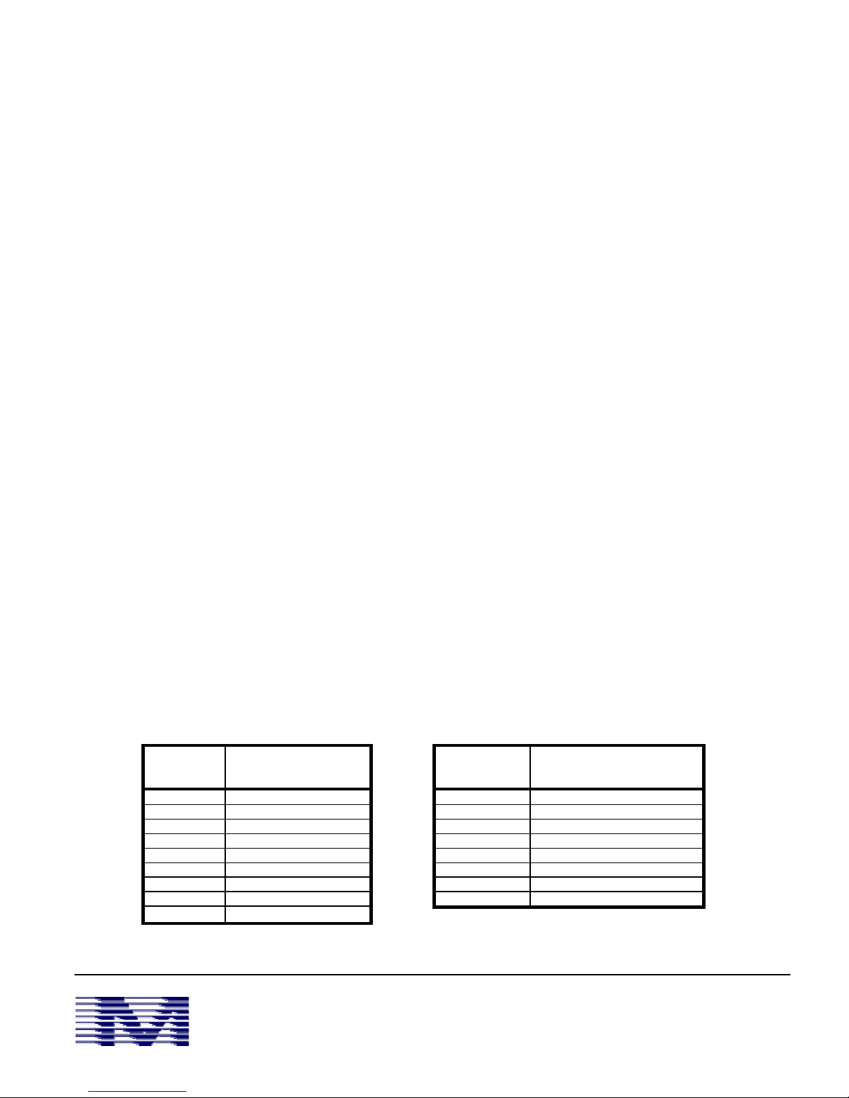
Pinout Diagrams
RS-232 Asynch Serial port (DCE) RJ-45 Ethernet ports
Pin Number
1 DCD Out
2 Data Out
3 Data In
4 N/C
5 Signal Ground (SG)
6 N/C
7 RTS In
8 CTS Out
9 N/C
Mainstream Data
Signal Name or Function
Pin Number
Signal Name or Function
1 TX+
2 TX3 RX+
4
5
6 RX7
8
Mainstream Data, Inc.
375 Chipeta Way, Suite B
Salt Lake City, UT 84108
Main: (801) 584-2800
Support: (800) 473-3332
 Loading...