

Page 1

EPC CHARGING CONTROLLER
OPERATING INSTRUCTIONS
Page 2

2
TABLE OF CONTENTS
CHAPTER 1 INTRODUCTION
1.1 ABOUT THIS DOCUMENTATION ........................................................ 3
1.2 Recycling and Disposal ........................................................................3
CHAPTER 2 SAFETY INSTRUCTIONS
2.1 CAUTIONS & DANGERS .................................................................. 4
2.2 Fuses ......................................................................................4
2.3 Repairs .....................................................................................4
CHAPTER 3 DESCRIPTION
3.1 EPC FEATURES ............................................................................ 5
3.2 Application Example .......................................................................... 6
3.3 Function Description ........................................................................6 - 7
3.4 LED Display & Troubleshooting .................................................................8
CHAPTER 4 MOUNTING
4.1 MOUNTING ONTO STANDARD RAIL ................................................... 9
CHAPTER 5 CONNECTION
5.1 CONNECTING TERMINALS & TERMINAL ASSIGNMENT ......................... 10 - 12
5.2 230 V AC Power Supply .......................................................................13
5.3 Functional Grounding ........................................................................14
5.4 Relay Outputs ..............................................................................14
CHAPTER 6 SERVICE & MAINTENANCE
6.1 REPLACING THE DEVICE ............................................................... 15
6.2 Cleaning ...................................................................................15
CHAPTER 7 DIMENSIONAL DRAWINGS
7.1 DIMENSIONAL DRAWINGS ............................................................. 16
Page 3

3
1
.
1.1 ABOUT THIS DOCUMENTATION
PURPOSE OF THIS DOCUMENTATION
ese Operating Instructions contain all the information you need for commissioning and using the Mainpine EPC charging controller.
ey are intended for use by electrically skilled persons who commission the device.
SCOPE OF VALIDITY OF THIS DOCUMENTATION
is documentation is valid for all components of the Mainpine EPC charging controller specied in these Operating Instructions and
describes the delivery state as of March 2014.
THIS PRODUCT IS BASED ON THE IEC 61851 AND SAE J1772 INTERNATIONAL STANDARDS
TRADEMARKS
Mainpine EPC is a registered trademark of Mainpine, Inc.
1.2 RECYCLING AND DISPOSAL
e Mainpine EPC charging controller is ecologically compatible, and thus suitable for recycling. For environmentally compliant recycling
and disposal of your electronic waste, please contact a company certied for the disposal of such waste.
INTRODUCTION
Page 4
4
2.1 CAUTIONS & DANGERS
CAUTION: PLEASE OBSERVE THE SAFETY INSTRUCTIONS AND LEGAL NOTES
Installation requirements vary by country, state, and jurisdiction. It is the responsibility of the installer to ensure that the legal
installation requirements are met.
DANGER: VOLTAGE HAZARDS
Contact with live components can result in serious injuries. Disconnect the system and all devices from the power supply before
starting work.
2.2 FUSES
WARNING: UNDESIRABLE HEAT GENERATION OR FIRE DUE TO INADEQUATE
FUSING.
e internal fuses are designed only to protect the device itself. e system installer and plant operator are responsible for the
necessary line protection.
e relay outputs are not fused within the device. Without appropriate protection of the relay outputs, overloading can cause
undesirable heat generation or even re. e relay outputs are to be fused externally by the plant constructor.
2.3 REPAIRS
Repairs are not permitted. Defective devices must be disposed of in compliance with environmental requirements.
WARNING: DANGERS ASSOCIATED WITH UNAUTHORIZED OPENING OF THE
DEVICE
Unauthorized opening of the device might place the user in danger or result in substantial damage to property.
CAUTION: INVALIDATION OF THE MANUFACTURER’S WARRANTY DUE TO
UNAUTHORIZED ALTERATIONS TO THE DEVICE
Alterations to the devices are not permitted. Failure to observe this requirement shall constitute a revocation of the manufacturer’s
warranty.
2
.
SAFETY INSTRUCTIONS
Page 5
5
3.1 EPC FEATURES
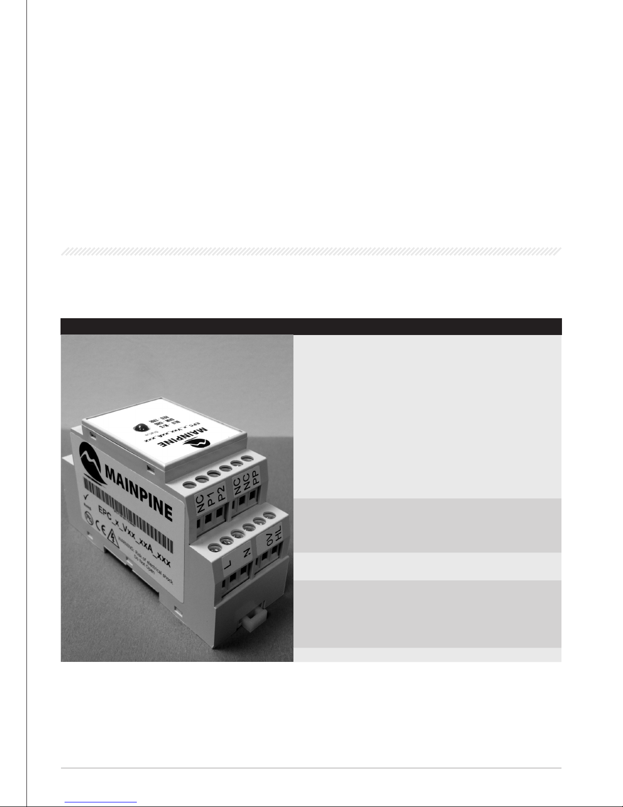
e Mainpine EPC charging controller is a product which is intended for use in charging stations for electric vehicles.
EPC CHARGING CONTROLLER FEATURES
DEVICE VERSIONS
• Mainpine EPC charging controllers have
part numbers in this format:
EPC_(1)_V(2)_(3)A_(4).
• (1) is either “T”, for tethered versions, or
“F”, for free cable versions.
• (2) indicates the hardware revision, e.g.
“21” or “23”
• (3) indicates the maximum charging
capacity, 16, 30, 32, 40, 50, 60, or 63.
• (4) indicates the rmware revision
AREAS OF
APPLICATION & USE
• Controlling the charging procedure of
electric vehicles
• For communication with the electric vehicle
according to IEC 61851 or SAE J1772
MOUNTING
Mounting onto standard rail according to
DIN EN 60715
CONNECTION
ELEMENTS
• Relay contacts for switching the load
contactor, interlock, signaling contact (de-
pending on model)
• Operating voltage input
• Vehicle interface
LED
Display of the operating state
3
.
DESCRIPTION
Page 6
6
3.2 APPLICATION EXAMPLE
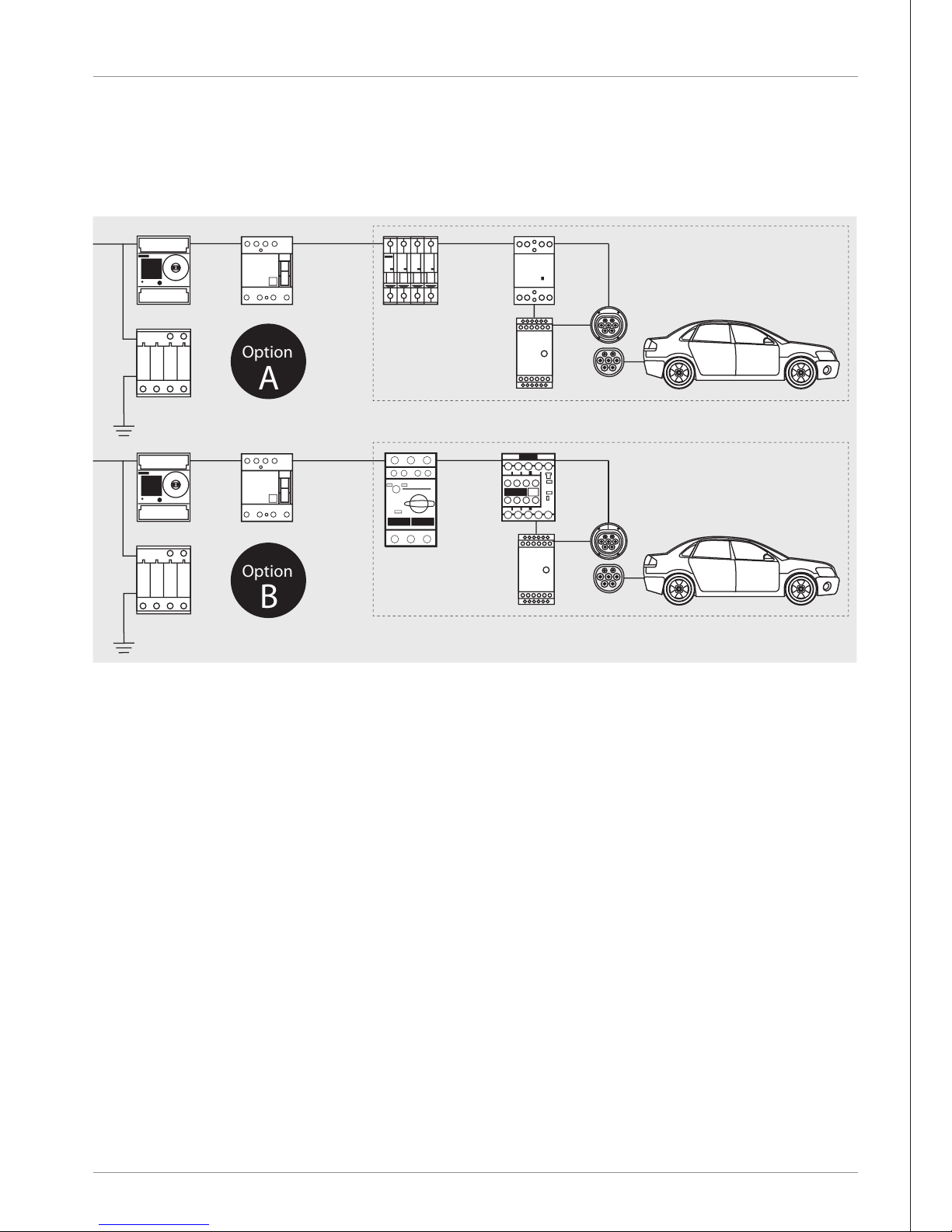
e following shows a schematic application example of an electric vehicle charging post with Mainpine components. For example, feeder
option A has a circuit breaker and an Insta contactor. Feeder option B has a circuit breaker and a SIRIUS power contactor.
3.3 FUNCTION DESCRIPTION
SEQUENCE OF CHARGING PROCESS
1. INITIALIZATION
After the operating voltage is applied, the module carries out initializations and function tests indicated by an LED ashing
sequence (which begins and ends with a two-second white indication) and then waits for vehicle connection.
2. CHARGING PROCESS
e module waits for a charging cable or vehicle to be connected (status A) and continually blinks the blue LED. If an approved
connecting cable has been connected (see Proximity) and status B is indicated by the vehicle, the module changes the LED to be
steady-blue and activates the interlock.
After interlocking, the charging enable P1/P2, P3/P4 or P4/P5 is activated (see Proximity) if the vehicle is signaling status C. e
charging process is activated, and the LED is changed to steady-green. If status D is indicated (ventilation required) then charging
and interlock are deactivated as the EPC does not provide a fan-enable mechanism, and the LED is changed to steady-red.
In the fault condition the charge enable P1/P2, P3/P4, or P5/P6 and the interlock are deactivated and the LED is changed to
continually blink red.
DESCRIPTION
Option
B
Option
A
Digital
E Meter
Ground
Fault
Operated
Circuit
Interrupter
Circuit
Breaker
Miniature
Circuit
Breaker
Insta
Contactor
SIRIUS
Power
Contactor
Socket Outlet
for Charging
Socket Outlet
for Charging
Mainpine
EPC Charging
Controller
Mainpine
EPC Charging
Controller
Surge
Arrester
Type 2
Ground
Fault
Operated
Circuit
Interrupter
Surge
Arrester
Type 2
Digital
E Meter
Page 7
7
3. STATUSES OF THE CHARGING VEHICLE
STATUS A: Vehicle is not connected
STATUS B: Vehicle is connected/not ready to receive energy
STATUS C: Vehicle is connected/ready to receive energy/no ventilation of the charging area is required in buildings
STATUS D: Vehicle is connected/ready to receive energy/ventilation of the charging area is required in buildings
STATUS E: Short-circuit/power supply disconnected from electric vehicle/electricity is not available/other power supply problem
STATUS F: Power supply is not available/other power supply problem
VENTILATION REQUIREMENT
WARNING: SUFFOCATION HAZARD WHEN CHARGING INDOORS
Without ventilation, a danger of suocation can arise due to gas build-up with some battery types when charging indoors. If the
charging process takes place indoors, forced-air ventilation should be installed. e Mainpine EPC charging controller does not mon-
itor the functionality of the forced-air ventilation.
PILOT CIRCUIT
e pilot circuit is used for the bi-directional exchange of information between the charging station and the vehicle. Via this signal, the
charging station indicates to the vehicle the maximum permitted charging current which the vehicle can call up. e operational read-
iness of the charging station is also indicated. Via this signal, the vehicle indicates to the charging station its current state of charging
readiness.
WARNING
Via the pilot signal, the EPC module species the maximum charging current that can be called up by the vehicle. is specied
current must be consistent with the line protection congured for the charging device and the rest of the plant conguration. Failure
to observe this notice can result in injury to persons or property damage.
PROXIMITY
With free cable installations the charging device detects the maximum current carrying capacity of the connected charging cable via the
proximity signal. e activated charging output coded in the pilot signal is no greater than the current carrying capacity of the charging
cable.
To ensure that the charging current does not exceed the rated capacity of the AC main power supply, there are dierent product variants
which each provide dierent maximum charging current presets (16A, 32A, and 63A - free cable; 16A, 30A, 40A, 50A, and 60A - tethered).
e product version that is used must be designed corresponding to the installed line protection of the charging station.
e 32A and 63A versions of the free cable Mainpine EPC charging controller are capable of generating dierent enabling signals depend-
ing on the current carrying capacity that is detected. For charging cables that have a current carrying capacity of 16A according to IEC
61851, relay P1/P2 is activated. e charging circuit that is activated by this must be designed with a suitable line protection for 16A.
For charging cables that have a current carrying capacity of 32A according to IEC 61851, relay P3/P4 is activated. e charging circuit
that is activated by this must be designed with a suitable line protection for 32A. For charging cables that have a current carrying capac-
ity of 63A according to IEC 61851, relay P5/P6 is activated. e charging circuit that is activated by this must be designed with a suitable
line protection for 63A.
DESCRIPTION
Page 8

8
INPUT CURRENT RESISTANCE INFORMATION
e Input Current (IC) resistance restricts the current maximum advertised by the EPC. e IC values are as described below:
MAX
no resistor (open, no resistor, IC not connected)
MIN
no resistor (no resistor, IC connected to ground)
80A
9090 Ω resistor
59A
2210 Ω resistor
39A
959 Ω resistor
19A
412 Ω resistor
79A
8060 Ω resistor
58A
2100 Ω resistor
38A
931 Ω resistor
18A
392 Ω resistor
78A
7320 Ω resistor
57A
2050 Ω resistor
37A
887 Ω resistor
17A
374 Ω resistor
77A
6650 Ω resistor
56A
1960 Ω resistor
36A
845 Ω resistor
16A
348 Ω resistor
76A
6190 Ω resistor
55A
1870 Ω resistor
35A
825 Ω resistor
15A
332 Ω resistor
75A
5620 Ω resistor
54A
1780 Ω resistor
34A
787 Ω resistor
14A
316 Ω resistor
74A
5230 Ω resistor
53A
1690 Ω resistor
33A
750 Ω resistor
13A
301 Ω resistor
73A
4870 Ω resistor
52A
1620 Ω resistor
32A
732 Ω resistor
12A
280 Ω resistor
72A
4530 Ω resistor
51A
1580 Ω resistor
31A
698 Ω resistor
11A
267 Ω resistor
71A
4220 Ω resistor
50A
1500 Ω resistor
30A
665 Ω resistor
10A
249 Ω resistor
70A
4020 Ω resistor
49A
1430 Ω resistor
29A
634 Ω resistor
9A
237 Ω resistor
69A
3740 Ω resistor
48A
1370 Ω resistor
28A
619 Ω resistor
8A
221 Ω resistor
68A
3570 Ω resistor
47A
1330 Ω resistor
27A
590 Ω resistor
7A
205 Ω resistor
67A
3320 Ω resistor
46A
1270 Ω resistor
26A
562 Ω resistor
6A
191 Ω resistor
66A
3160 Ω resistor
45A
1210 Ω resistor
25A
536 Ω resistor
65A
3010 Ω resistor
44A
1180 Ω resistor
24A
511 Ω resistor
64A
2870 Ω resistor
43A
1130 Ω resistor
23A
491 Ω resistor
63A
2670 Ω resistor
42A
1070 Ω resistor
22A
475 Ω resistor
62A
2550 Ω resistor
41A
1050 Ω resistor
21A
453 Ω resistor
61A
2430 Ω resistor
40A
1000 Ω resistor
20A
432 Ω resistor
60A
2320 Ω resistor
Input resistance less than 100-Ω, MIN, will cause the EPC to reduce the advertised current capacity to 7A for ve seconds after which
charging and the interlock will be disabled and the EPC will enter into a forced Status A until input current resistance is increased.
3.4 LED DISPLAY & TROUBLESHOOTING
LED DISPLAY
e EPC has a 3-color LED for displaying operating states and fault conditions. e LED can be lit in blue, green, or red. e meaning of
the individual displays is shown in the following tables:
OPERATING STATES:
LED DESCRIPTION OF OPERATING STATE
COLOR STATUS
NOT LIT NOT LIT
Device is not active, switched o
• No power supply
• Device defective
BLUE FLASHING (1 HZ)
Device is waiting to be connected to an electric vehicle (Status A)
BLUE STEADY
Electric vehicle connected, electric vehicle not ready for charging (Status B)
GREEN STEADY
Charging process active (Status C)
RED STEADY
Electric vehicle requires ventilation, charging deactivated (Status D)
RED FLASHING (1 HZ)
Communication fault detected, charging deactivated (Status F)
DESCRIPTION
Page 9

9
4.1 MOUNTING ONTO STANDARD RAIL
1. Clip the device (a) vertically onto the horizontal DIN rail (b).
2. Swing the device downward until the unlocking slider on the DIN rail clicks into place.
Figure: Mounting onto standard rail
4
.
MOUNTING
(a)
(b)
1. 2.
Page 10
10
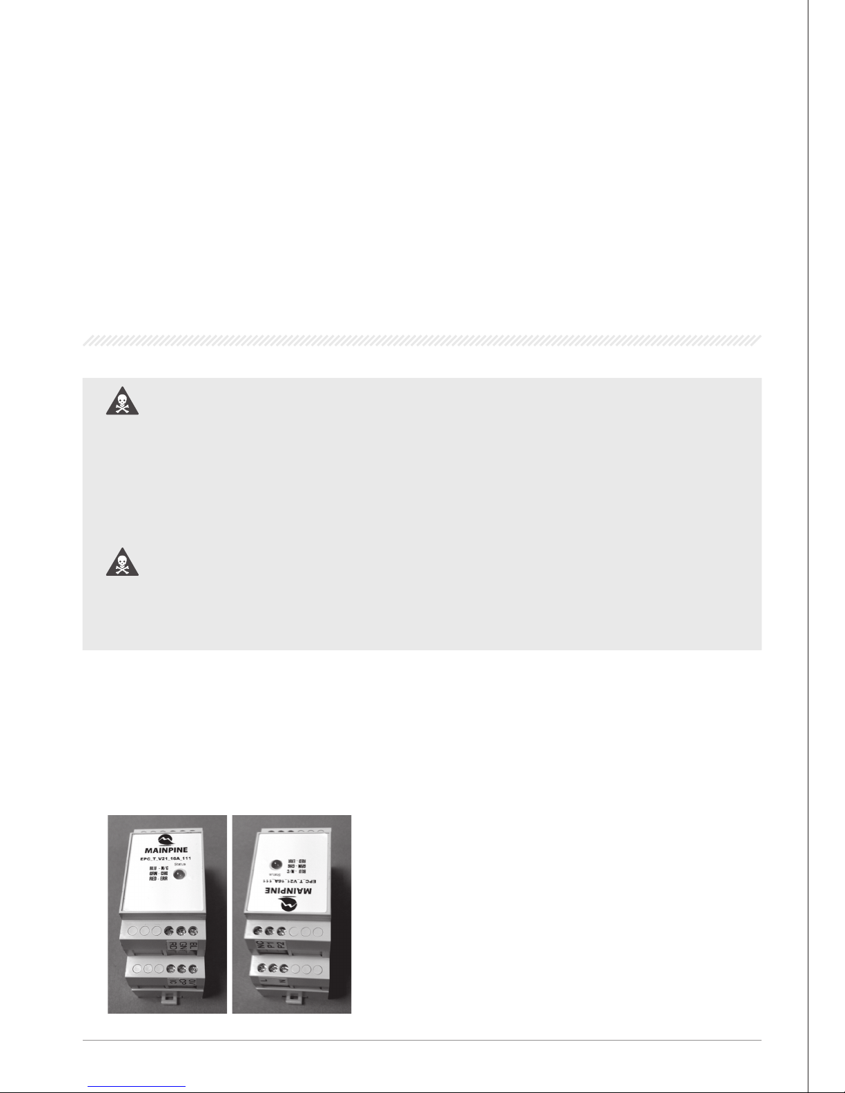
Depending on the device version the Mainpine EPC charging controller is connected to the EVSE in the following methods:
WARNING: UNDESIRABLE HEAT GENERATION OR FIRE DUE TO INADEQUATE
FUSING
e internal fuses are designed only to protect the device itself. e system installer and plant operator are responsible for the
necessary line protection.
e relay outputs are not fused within the device. Without appropriate protection of the relay outputs, overloading can cause
undesirable heat generation or even re. e relay outputs are to be fused externally by the plant constructor.
WARNING: VIA THE PILOT SIGNAL, THE MAINPINE EPC CHARGING CONTROLLER
SPECIFIES THE MAXIMUM CHARGING CURRENT THAT CAN BE CALLED UP BY THE
VEHICLE. is specied current must be consistent with the line protection congured for the charging device and the rest of
the plant conguration. Failure to observe this notice can result in injury to persons or property damage.
NOTICE
Connect the terminal (L/N) with the main last.
5.1 CONNECTING TERMINALS & TERMINAL ASSIGNMENT
TETHERED VERSION
“Tethered” means that the charging cable is permanently connected to the
EVSE.
P3-P6 are not present and relay 1 will energize for all charging currents. us,
the RCBO should be rated at the maximum current conguration of the EPC.
5
.
CONNECTION
Page 11
11
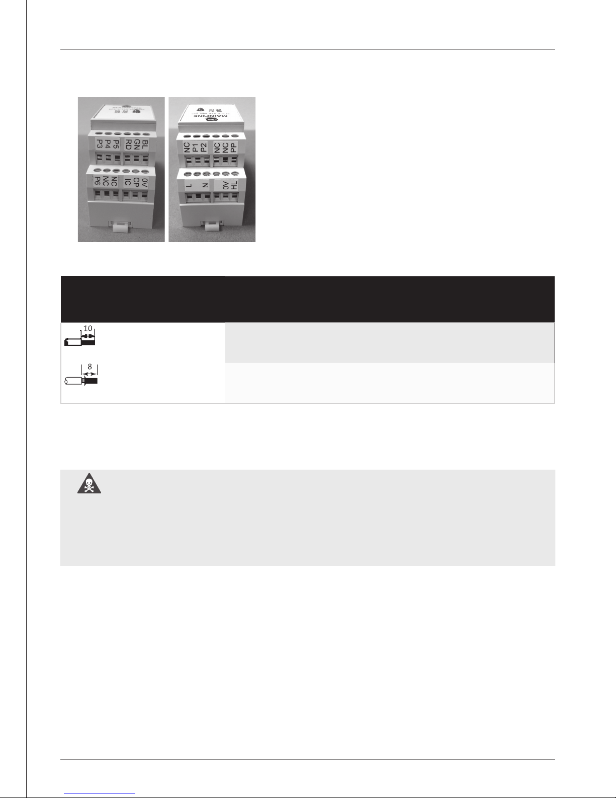
FREE CABLE VERSION
“Free” means that the charging cable is not permanently connected and that
the user is expected to provide their own.
Relay 3 (P5/P6) is energized for cables connected which support 63A current
capacities. Otherwise, relay 2 (P3/P4) is energized for cables connected which
support 32A current capacities. Otherwise, relay 1 (P1/P2) is energized when
the cable supports 16A current capacity.
STRIPPED LENGTH PERMISSIBLE CONDUCTOR
CROSS-SECTIONS OF
TERMINALS
LINE TYPES ACCORDING TO
AWG
Single-Core
0,5 ... 2.5 mm2 20 ... 14
Finely Stranded
• with core ends prepared: 0.5 ... 2.5 mm2
• without core ends prepared: 0,5 ... 2.5 mm2
20 ... 14
NOTICE
e temperature stability of the cable used must be designed for at least for 75°C. Failure to observe this can result in injury to
persons or property damage.
WARNING: THE CONDUCTOR CROSS-SECTIONS MUST BE DESIGNED CORRESPONDING TO A STANDARD-COMPLIANT SYSTEM CONFIGURATION.
e cables that are to be connected must be designed according to the respective type of circuit. Failure to observe this notice can
result in injury to persons or property damage.
CONNECTION
Page 12
12
CONNECTION
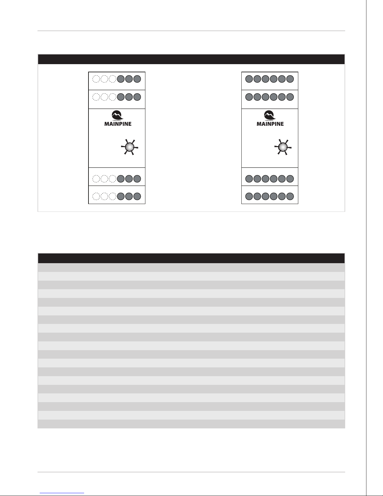
EPC TERMINAL ASSIGNMENT
EPC TERMINAL ASSIGNMENT
TERMINAL DESCRIPTION
L (LINE)
is is where the AC ‘live’ or ‘line’ connection is made (90-264V @ 50/60 Hz AC)**
N (NEUTRAL)
is is where the AC ‘neutral’ connection is made (90-264V @ 50/60 Hz AC)**
0V (GROUND)
is is where the ‘ground’ connection is made**
ML (MOTOR LOCK)
is provides 12V 300mA for 500 ms to engage the lock
MU (MOTOR UNLOCK)
is provides 12V 300mA for 500 ms to disengage the lock
HF (LOCK FEEDBACK)
Reads lock feedback
NC (NOT CONNECTED)
P1
Relay 1 live from RCBO*
P2
Relay 1 coil on the contactor*
P3
Relay 2 live from 32A RCBO
P4
Relay 2 coil on the 32A contactor
P5
Relay 3 live from 63A RCBO
P6
Relay 3 coil on the 63A contactor
PP (PROXIMITY PIN)
is connects to the PP connector on the IEC61851 EVSE connector
GN (GREEN LED)
For external LED connection for green indication (5V 30mA)
BL (BLUE LED)
For external LED connection for blue indication (5V 30mA)
RD (RED LED)
For external LED connation for red indication (5V 30mA)
CP (CONTROL PIN)
is connects to the CP connector on the IEC61851/J1772 EVSE connector
IC (INPUT CURRENT PIN)
is connects to the IC resistor, switch, or dial
* On tethered installations the RCBO and contactor should be rated according to the maximum current capacity of the EPC. On free-cable
installations the RCBO and contactor should be rated 16A.
** For 120-370V DC on L, connect N to ground (0V).
TETHERED VERSION FREE CABLE VERSION
BL GN RD
EPC_T_V21_16A_111
BLU - N/C
GRN - CHG
RED - ERR
BLU - N/C
GRN - CHG
RED - ERR
STATUS
STATUS
EPC_x_Vxx_xxA_xxx
N NC L
OV CP IC
P2 P1 NC
P3 P4 P5 RD RL GN
ML MU HF N NC T
P6 NC NC IC CP OV
PP NC NC P2 P1 NC
BLU - N/C
GRN - CHG
RED - ERR
STATUS
EPC_x_Vxx_xxA_xxx
P3 P4 P5 RD RL GN
ML MU HF N NC T
P6 NC NC IC CP OV
PP NC NC P2 P1 NC
Page 13
13
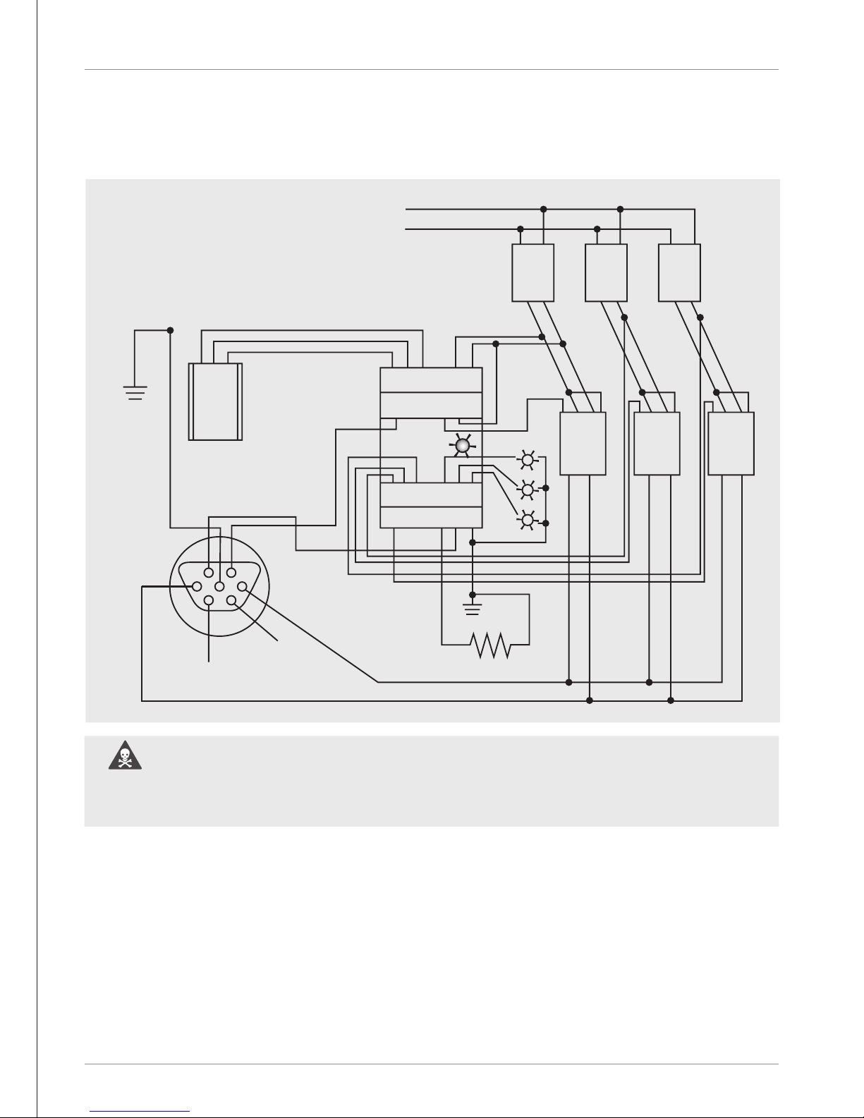
5.2 230 V AC POWER SUPPLY
WIRING EXAMPLE 230 V AC
WARNING: THE EXTERNAL CONTACT BLOCKS USED MUST BE FLOATING AND
SAFELY SEPARATED FROM UNSAFE CIRCUITS.
Failure to observe this can result in injury to persons or property damage.
CONNECTION
L
N
(N)
(L3)
(L2)
(L1)
16A
RCBO
A1 L1 L2 A2
63A
Contacter
L1 L2
A1 L1 L2 A2
32A
Contacter
L1 L2
A1 L1 L2 A2
16A
Contacter
L1 L2
PP NC NC
ML MU HF
P3 P4 P5
P6 NC NC
RD GN BL
IC CP 0V
Mainpine
P2 P1 NC
N L
Hatch
Lock
Solenoid
(Control Pilot)
(Proximity)
Input Current Resistor
32A
RCBO
63A
RCBO
Page 14
14
5.3 FUNCTIONAL GROUNDING
VEHICLE INTERFACE ACCORDING TO IEC 61851
1. Connect the terminals “CP” and “PP” (on free versions only) directly to the vehicle connector.
2. First connect the ground connection of the vehicle interface to the 0V reference point and then route this potential from there.
DANGER: NEVER USE THE TERMINALS OF THE MAINPINE EPC CHARGING
CONTROLLER AS A 0V REFERENCE POINT.
Always route this externally from the device! e 0V reference point within the plant must be dimensioned according to the
anticipated current of the plant itself. e EPC connection to the 0V is only a functional ground. Failure to observe this notice can
result in electric shock or damage to property.
5.4 RELAY OUTPUTS
We recommend single fusing with 230/400 V 10 kA circuit breakers, 1-pin, C, 2 A, T = 70 mm, item no.
SHUTDOWN OF POWER BRANCH
According to IEC 61851, a shutdown of the power branch on completion of the charging process within 100 ms is required. e Mainpine
EPC Charging Controller deactivates the relay output within this requirement after detecting the shutdown criterion.
WARNING: THE SHUTDOWN OF THE POWER BRANCH, IN PARTICULAR THE POWER
CONTACTOR, IS TO BE DESIGNED IN SUCH A WAY THAT THE ENTIRE IMPACT CHAIN
DOES NOT EXCEED THE REQUIRED 100 MS.
Failure to observe this notice can result in death or serious physical injury.
CONNECTION
Page 15
15
6.1 REPLACING THE DEVICE
MAINTENANCE
e Mainpine EPC charging controller is maintenance-free.
WARNING: THERE ARE NO USER-REPLACEABLE FUSES WITHIN THE EPC
MAINPINE EPC CHARGING CONTROLLER REPLACEMENT
REQUIREMENT: Ensure that the plant and the device itself are de-energized.
DANGER: VOLTAGE HAZARDS
Contact with live components can result in serious injuries. Disconnect the system and all devices from the power supply before
starting work.
PROCEDURE:
1. Disconnect the wiring from all EPC connector terminals.
2. Disassemble the device by pulling the locking slider on the back of the device down and swivel the device away from the DIN rail and
remove it.
3. Install the new device by clipping the top locking guide onto the DIN rail and swinging it down until the locking slider clicks into place.
4. Reconnect the wiring.
5. Switch on the power supply for the device and the main power for the unit feeder again.
6.2 CLEANING
Cleaning of the device is not intended or permissible.
6
.
SERVICE & MAINTENANCE
Page 16
16
7
.
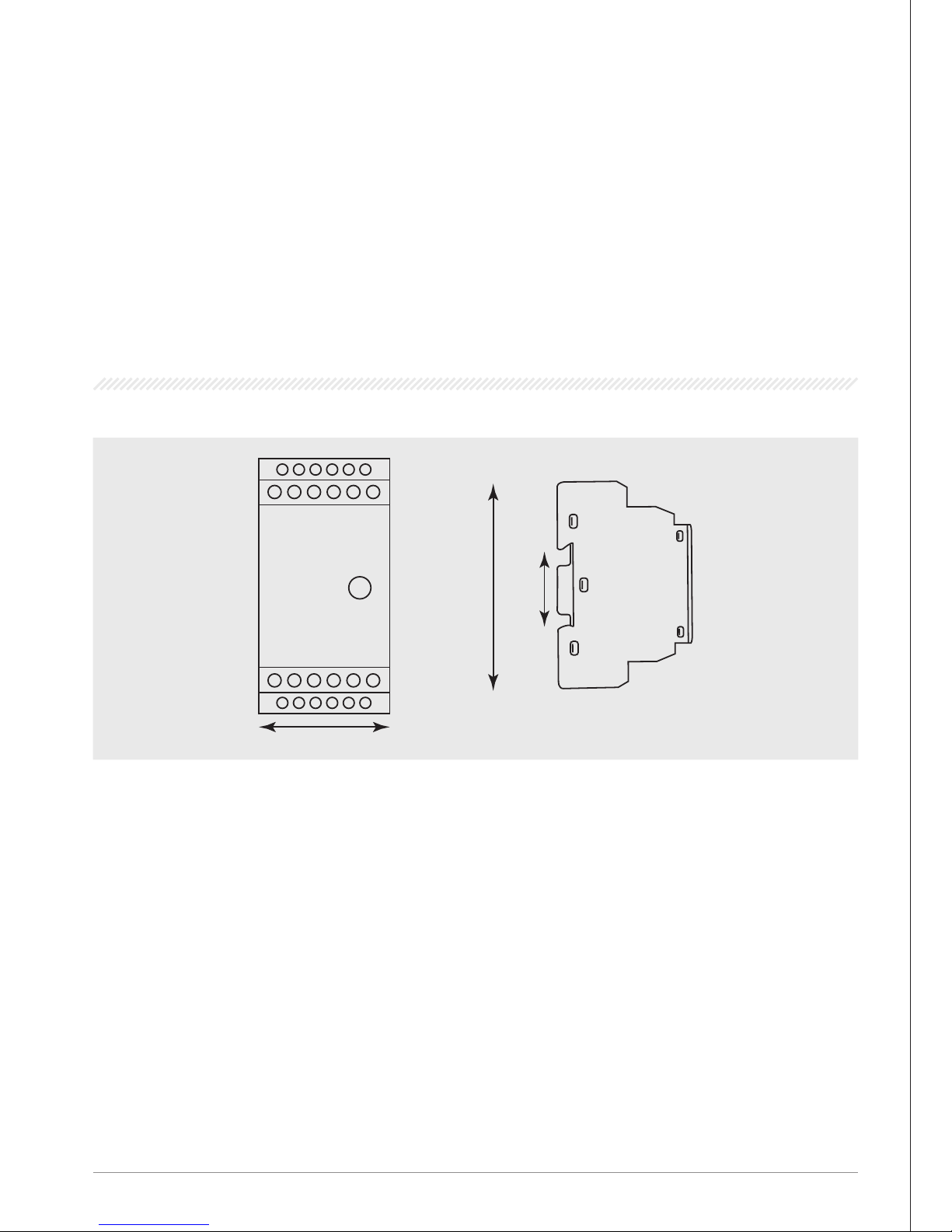
DIMENSIONAL DRAWINGS
91 mm 35 mm
35 mm
 Loading...