

Page 1
OWNER'S MANUAL
MANLEY
SLAM!
Stereo Limiter And Micpre
MANLEY
LABORATORIES, INC.
MANLEY LABORATORIES, INC.
13880 MAGNOLIA AVE.
CHINO, CA. 91710
TEL: (909) 627-4256
FAX: (909) 628-2482
http://www.manleylabs.com
EveAnna's email: emanley @ manleylabs.com
Tech Support: service @ manleylabs.com
REV. 11-22-2004
Page 2

CONTENTS
SECTION PAGE
INTRODUCTION 3, 4
POWER SUPPLY 5
BACK PANEL & CONNECTING 6, 7, 8, 9
FRONT PANEL 10, 11
METERING 12, 13, 14
LIMITERS, HINTS, ETC. 15, 16, 17, 18
DIGITAL RAMBLINGS 19
THE GUTS, INSTALLING THE A/D/A, ALIGNMENTS 21, 22, 23, 24,25
TROUBLESHOOTING 26, 27
MAINS CONNECTIONS 28
SPECIFICATIONS 29,30
ADDENDUM FOR SLAM! MASTERING 32,34
WARRANTY 35
WARRANTY REGISTRATION 36
APPENDIX 1 - EXAMPLE SETTINGS 37
APPENDIX 1 - TEMPLATE FOR STORING SETTINGS 38,39
2
Page 3

INTRODUCTION
THANK YOU!...
for choosing the Manley SLAM!. This unit combines Mic and Instrument Preamps, 4 limiters, comprehensive
metering and is ready for or already has the digital converter option. As one might expect, the basic operations are
fairly simple and instructions may not be needed - but - the SLAM! has a lot of advanced features, and we strongly
recommend reading through the manual. There are a lot of tricks and features that are not so obvious.
In truth, the SLAM! started with the idea of an updated Electro-Optical Limiter and the original working name was
ELOP II. That didn't last long. First we developed a fast FET limiter, decided that fast LED metering was approriate,
then added a mic pre, decided that this box would make the ideal "analog insert in a digital world", then added almost
every request and suggestion the customers had given us over the years. And somewhere during all this, decided each
little part had to be right, and much was going to be quite new and elaborate. In the end, ELOP II was not at all
descriptive and after a 'name this box' contest on our website it became the SLAM!.
We can start right at the basic tube circuits. These designs are unlike any others we know of, including previous
Manley circuits, so this is not a box with an old mic pre combined with an old Opto Limiter and a borrowed FET
limiter with a conventional digital converter tossed in the salad. This is all new. The tube circuit is a hybrid FET/
tube design first used in the Manley Steelhead phono preamp and provides the advantages of both technologies. You
get the low noise of FETs, the headroom of tubes, the gain of both and lower distortion than either typically, and
a new texture in your tool kit.
This is the beginning of the story and continues through the product and the manual. Some manuals seem to imply
that if you use 'this box' then you are an instant mastering engineer or top producer with all the tools they use. This
strange manual is filled with warnings, caution flags, grumblings about some aspects of digital and has extended
quotations from other other manufacturers. Our intention is to help the user, supply a bit of under-reported info, and
give equal time to both what might help provide the sound you've been looking for and what might be considered
questionable or dangerous to your music. The SLAM!, like other powerful processors, can be great or horrible
depending on how it is used or abused and if something here helps avoid disasters, then we have happy customers.
GENERAL NOTES
LOCATION & VENTILATION
The Manley SLAM! must be installed in a stable location with ample ventilation. It is recommended, if this unit
is rack mounted, that you allow enough clearance on the top of the unit such that a constant flow of air can move
through the ventilation holes. Airflow is primarily through the bottom panel vents and out through the top.
You should also not mount the SLAM! where there is likely to be strong magnetic fields such as directly over or under
power amplifiers or large power consuming devices. The other gear's fuse values tend to give a hint of whether it
draws major power and is likely to create a bigger magnetic field. Magnetic fields might cause a hum in the SLAM!
and occasionally you may need to experiment with placement in the rack to eliminate the hum. In most situations
it should be quiet and trouble free.
We also suggest that you get familiar with the back panel switches and jacks before it gets mounted in a rack. If you
have the digital option, experiment with the filter settings, dither, etc to find your favorite settings, then rack it.
WATER & MOISTURE
As with any electrical equipment, this equipment should not be used near water or moisture. Beer is OK though.
SERVICING
The user should not attempt to service this unit beyond that described in the owner's manual.
Refer all servicing to your dealer or Manley Laboratories. The factory technicians are available for questions by
phone (909) 627-4256 or by email at <[email protected]>. Fill in your warranty card! Check the manual -
Your question is probably anticipated and answered within these pages...... RTFM
3
Page 4

The Swiss Army Knife
First Things First
The SLAM! is an unusual product that doesn't quite fit into a simple
catagory. We get questions like "Why have a mic-pre on a limiter?",
"Why have a DAC on a mic-pre?" and "Why so many input and
output jacks?" and "Why no hard-wire bypass on this mastering
processor?". And the only answer is "It's not just a ....., it does a lot
more". It isn't a channel strip - no EQ, besides being stereo. It isn't
just another front-end for the workstation. It isn't just a mastering
processor. Maybe the SLAM! is a new catagory.
The SLAM! is intended to be the reference analog I/O (input/output)
for a digital studio - the first choice analog insert for digital with
strengths as an input device, output device and killer go-louder box.
Sometimes digital gets cold and sterile, and people reach for tube
processors for particular vintage colors, the 'warmth factor', the
ballz, the thing that plug-ins or digital processors are not quite doing
for 'em. So the SLAM! has an outrageous D/A and A/D option which
sets it up as 'THE' Insert, and can be used with any other analog (or
digital) gear to process tracks already on hard disk and then return
them as pristene or mangled as desired. This requires great converters
and analog circuits that can be super clean or dirty or in-between.
The DAC can be pristene high-end solid state, tube, or driven hard
for a wide range of colors. The ADC uses a transformer (iron) for its
front end (and no chips) and is intended to be a 'warm' converter,
because most everybody has the other kind.
The SLAM! is a an outboard limiter and a new low-noise high gain
tube mic-pre, and a mastering processor, and a DI, and possibly the
best converter in your rack. As a mic pre it offers about 70 dB of gain
and a new circuit, unlike any previous Manley PreAmp. The gain
stages are based on a circuit developed by Mitch Margolis for the
SteelHead phono pre-amp. Mitch also designed the VIPRE. The
SLAM! can be used as a mastering processor (not a multi-band
limiter), a processor that real mastering engineers use to create
loudness without messing up the mix. As a DI or Instument Input it
offers 2 impedances 100K and 10 meg ohms, plenty of gain,
limiting, and if you want to have fun use both channels with your
fave EQ inserted between, and use the optional A/D straight into the
workstation.
Swiss army knife is the most appropriate description. A multipurpose, well constructed, generally useful tool. The analog to
digital converters also have the Swiss connection. They are designed
and built by a Swiss company called Anagram Technologies who
are not well known in pro-audio but getting an enviable reputation
in the high-end audiophile market. Stereophile Magazine in April
2002 (p77&79) named them the 'kings of digital filters' and they
build converters for Audio Aero, Camelot Technologies, Nagra, and
Manley.
What makes Anagram's converters so special? The DACs upsample to 192K and in the process remove jitter almost completely
and to the point where A/D/A worst case jitter components are well
below the -144 dB measurement limit of 24 bit digital. The analog
to digital converter similarly has a permanent sample rate of 192K
and then down-samples to any of the common data rates like 48K.
This provides both the audible benefits of 192K and the practical
benefits of a 48K data rate, like relaxed requirements for giga-bits
of storage space. This is all done with proprietary software running
on a pair of very fast SHARC DSP chips and 40 bit floating point
math.
We only have a few simple suggestions for your first few dates with
the SLAM!.
1) Don't rack mount it until you are familiar with the back panel and
have experimented a bit with the jacks and switches that you might
use later. No problem racking it, but this way is easier at first.
2) Watch those levels. There is a lot of gain and ways to manipulate
gain on the SLAM!. We have seen guys set up 30 dB of boost to a
line signal, 30 dB of limiting and were not aware of how drastic those
settings might be because they were unfamiliar with the box. On he
LED meters, one segment = 1 dB (approximately), and if you see the
LEDS go half way down, you are hitting 13 dB of limiting which is
generally drastic. Most engineers prefer 6 dB or less limiting. You
need to use your ears, and your eyes. Common mistake.
a) Unity gain for line inputs is near 12:00 for the INPUT and
OUTPUT controls. Begin with the ELOP and FET thresholds fully
clockwise (5 oclock). A good starting point.
b) To set INPUT levels start with the VU on INPUT and the VU
attenuator at the "0dB" especially as you become familiar with the
SLAM!. You have to be aware that practically all the knobs and
switches affect level and gain and that you want to start off on the
right foot, so get the INPUT set first. Then set Thresholds and Output
level. Most early confusion has been due to level settings.
c) The LED PEAK METER (audio mode) is most useful to view
when setting up the limiters and comparing how much louder it can
get while hitting the same peak level. Compare your original peak
level in Bypass to the level possible with limiting engaged.
3) This is a limiter and limiters generally can create weird distortions
especially when the gain reduction is deep and releases are fast. The
SLAM! FET limiter has very fast releases so it can be dangerous.
The OPTO is easier to use because the attack & release are slower
which is why opto's have always been popular. Sometimes we want
the ease of opto and the speed of FET, and using the FET gently to
'clean up' the overshoots of the opto is pretty easy too. With the FET
limiter alone, some experimentation and critical listening is a must.
Different songs and sounds seem to want different settings and one
may often be surprised by the optimum setting.
4) Because the SLAM! is old-school analog, the limiters won't have
the 'precision' of a digital limiter that can be easily set to hold peaks
within 0.1 or 0.2 dB of clipping. If you intend to use it as a brick wall
limiter before the A to D converter as a method to be safe/lazy/
clever, in an attempt to get hot levels within .2 dB of digital clipping
you may be creating the worst case scenario for an analog box. It is
difficult to set the SLAM! up to do that. It can be pretty good IF you
take the time to carefully set the controls. Foolproof and easy - no,
but if you want 'easy', then the safest way is to accept -2 to -5 dB DFS
(23+ bits), and use a digital limiter like an L1 or L2 for the last few
dBs. The combination provides the best of both worlds. Another
approach is to try the "CLIP" setting plus the OPTO which is a bit
easier and may or may not be as audible. It might not be worth being
obsessed with hitting -.1 dB DFS and focus on the sound instead.
5) Once you have found your favorite back panel settings, feel free
to rack mount the SLAM!. Yes, you can leave Phantom on all the
time. Old consoles didn't have phantom switches and it was always
on - no problem. Most guys stick to one sample rate, 24 bits, and one
choice of filters.
4
Page 5

MANLEY SLAM!
POWER SUPPLY UNIT
electric shock, do not expose this unit
refer all servicing to qualified personnel only
WARNING:
to reduce the risk of fire or
to rain or moisture.
CAUTION:
risk of electric shock.
do not open, high voltage.
line voltage
switch
replace fuse
with same
type and rating
FUSE
ON
N9512423
5
4
3
2
POWER
1
1) POWER MULTI-PIN: 16 PIN AMP connector that screws into the matching socket on the back of the SLAM!. This
should be connected first. Rotate the whole connector until it mates with the socket, then just a turn or so on the outer
ring clockwise will complete the mating. Force will NOT be needed. The cable is 6 feet long and keeping the supply 612" away from other gear reduces the possibility of induced hum, though this supply won't radiate much. The supply
may get reasonably warm, and this is an intentional trade-off to keep those magnetic fields minimal.
NOTE: The bulk of the power supply will not turn on (including the LED) unless this connector is inserted, because the
SLAM! remote controls the power for most of the Power Supply Unit.
2) IEC POWER SOCKET: Use the supplied IEC cable to connect the Power Supply Unit to wall current. This supplied
cable should be the proper type for your country.
3) POWER TOGGLE: "ON" is marked. Note that BOTH this toggle has to be in the 'ON' position and the SLAM! front
panel red 'POWER' button has to be pushed to turn on the SLAM!.
4) FUSE: The fuse protects you and the SLAM! in case of a catastrophe. Replace only with the same value and type.
Failure to do so voids the warrantee. For 117 volts AC mains this fuse is a 2 Amp standard 1/4" SLO-BLO MDL 2. For
220 volts AC mains this fuse is a 1 Amp standard 1/4" SLO-BLO MDL 1. A blown fuse often looks 'blackened'. Several
blown fuses indicates a problem needing repair. Both the Supply and SLAM! should be returned to the dealer or Manley
Labs for service if the correct value fuses continue to blow.
5) VOLTAGE CHANGE-OVER SWITCH. This should be set to the proper voltage for you country by the factory. The
switch is marked, and in general a good habit to verify this setting is correct before plugging any new gear in and turning
it on. The carton the SLAM! arrives in will also be marked for 117 or 220.
In case you were wondering about the handle, it is to mechanically protect the switches and fuse.
The 4 mounting screws allow the supply to be mounted in a rack or screwed down to something.
5
Page 6

This page will have connection example diagrams
6
Page 7

THE BACK PANEL
INSTRUMENT
DAC OUTPUT
UNBAL OUTPUT
FULLIN = +4dBu
HALFIN = -10 dBv
IN =100K OHM
1/2 IN =
1/4" BYPASSES
XLR O/P. XLR
DRIVES ADC
CHANNEL 2
ALANCED INPUT
B
10 MEG
TRANSFORMER
BALANCED OUTPUT
EXT LINK
(5.1 etc)
I/P OPTO
CHANNEL
2
1
SEND
SC
O
RTN
OPT
SEND
FET SC
INSERT INSERT
RTN
EXT LINK
)
(5.1
SC MIX
SC MIX
I/P FET
CHAS
GROUND
CIRCUIT
XLR PINOUT:
TRANSFORMER BALAN
PIN 1 =
SIS
PIN 2 = HOT =
PIN 3
MIC = 2400 OHMS,
1/4 PHONE JACKS :
BAL
INSTRUMENT = UNBAL, 100K INPUT Z
DAC OUT = BALANCED, +4dBu
UNBAL OUT = +4 dBu (not -10 dBv)
(INSERTING PHONE JACK DISABLES
XLR O/P. XLR O/P CAN THEN BE USED
FOR DIRECT ADC INPUT (SEE MANUAL
SERIALNUMBER
DESIGNED BY HUTCH
ANAGRAM TECHNOLOGIES,
JERRY GARSZVA, E. MANLEY
M. MARGOLIS, B. HERNANDEZ
CED
SHIELD = GROUND
POSITIVE PHASE
PHASE
= LOW = NEGATIVE
LINE = 50K OHMS
ANCED INPUT = 2400 / 50K OHMS
HALF OUT = 10 MEG OHM FET
)
PHONE (909) 627-4256 FAX(909) 628-2482
ELECTRIC SHOCK.
CAUTION -RISK OF
DO NOT OPE
TU
MANLEY LABORATORIES, INC
13880 MAGNOLIA AVE., CHINO, CA 91710
N. REFER SERVICIN
ONLY
UALIFIEDPERSONNEL
Q
DO NOT HOT PLUG
RN OFF POWER SUPPLY
m
www.manleylabs.co
G TO
ANTOM
PH
POWER 48V
OFF
MUTE MONITORS
THEN PULL
TOTOGGLE
ADC
DAC
FILTER
FILTER
40K
NORM
80
20K
20K D
NORM
44.1
ADC
SAMPLE RATE
88.2
48
DITHER
OFFOFF
96
80
20K A
AES/EBU IN RATE
WORD CLOC
SUPER CLOCK
WORD
LENGTH
ADC
K
K
CLOCK
24
20
16
K
NOISE
SHAPE
WORD
AES
EBU
I
N
AES
EBU
OUT
IN
CHANNEL 1
ANCED INPUT
BAL
TRANSFORMER
BALANCED OUTPUT
IN =100K OHM
1/2 IN =10 MEG
1/4" BYPASSES
XLR O/P. XLR
DRIVES ADC
INSTRUM
DAC OUTPUT
BALANCED +4
UNBAL OUTPUT
FULLIN = +4dBu
HALFIN = -10 dBv
ENT
1 17
24 23 22 21 20 19 18 11 12 13 14 15 16 8 9 10 7 2 3 4 5 6
This is just a description of the various jacks and switches on the back. We suggest that you might want to not rack-mount the SLAM! until
you've spent some time becoming familiar with the various patching and switches. Sorry, but the back panel is more complex than most
gear and there are options galore. That's what happens when you get what everybody asks for.
For simple maps that show a few examples of how to patch the SLAM!, check out Page
1) POWER CONNECTOR. First verify the POWER SWITCH on the front panel is off (out) and Outboard Power Supply is off (toggle
towards FUSE). The Outboard Power Supply has a captive 6 foot cable, with the mating plug. There is a painted white dot on the plug that
should face UP and/or gently rotate it to find the "key" or where it fits. Force is definately not needed. Rotate the ring on the front of the
connector CLOCKWISE about 1 turn, which locks the connector in place.
The SLAM! uses a trickle of power to remote control the power of the main supply. This means the Outboard Power Supply can not be
turned on without it being connected to the SLAM!. This is a safety feature. Also, with that exception and the +&-6 volt supply used for
tube filaments (heaters) all other pins are protected from passing current or a charge stored on power supply capacitors. In other words,
its pretty safe, and that you can't get a shock, and can't power it up hot but still better to have both power switches off to connect this plug.
2) CHANNEL 1 INPUT). This is a Neutrik Combo jack that accepts XLRs, 1/4" mono phone plugs, 1/4" balanced phone plugs. This is
both the LINE INPUT and the MIC INPUT. Phantom Power (17) is not advised except for some MICs, and in particular FET condensor
mics and some rare exceptions that require it. If Phantom is ON, turn it off before patching into this jack (or any other mic patching) or
at least turn the monitors, headphones, etc down because there will be a loud speaker killing POP. Contrary to urban myth, it is highly
unlikely Phantom Power will damage any mic or cause it to sound different, except during patching. It is a good idea, not to have Phantom
on for LINE inputs, as it might be possible to damage something with the 48 volts if you select MIC (which can enable phantom).
3) CHANNEL 1 OUTPUT. This is a transformer floating balanced +4 dBu output (Pin 2 hot). It is equally happy feeding balanced or
unbalanced inputs but for unbalanced inputs, be sure that the XLR's Pin 3 is grounded or connected to Pin 1 or the shield. There is also a
transformerless unbalanced 1/4" phone jack output described below (6).
4) INSTRUMENT INPUT. This is a 1/4" mono unbalanced high Z input for guitars, basses, synths, etc. It has about 30 dB more gain than
the Combo jack input and uses the mic-pre. The input impedance is 100K suitable for synths and guitar processors/amp simulators but might
be a bit dull for some guitars direct. For very high Z (10 meg ohm) physically insert the jack half way. Cool trick, huh? This will sound
brighter for many guitars and basses, but should have little or no effect if any electronics are between the guitar and input.
5) DAC OUTPUT. (Left) This is a direct balanced +4 dBu output of the DAC if that option is installed. We calibrate the output so that
Digital Full Scale = 8.0 volts and that Digital -14 = +4 dBu. Other calibration or reference levels requires a simple internal trimmer tweak.
6) CHANNEL 1 UNBALANCED OUTPUT. This jack provides an unbalanced +4 dBu output pre-transformer. It can also provide a semi-
pro or consumer -10 dBv with plug inserted half way. Most other Manley gear makes this unbalanced output jack entirely bypass the
transformer and thus disables the balanced XLR output. There is an internal jumper to provide this mode, if needed (see page XX). In the
SLAM!, the transformer is also used to drive the A to D converter, which we did not want to 'mysteriously lose' when they plugged into
the 1/4" output. With the jumper in the alternate position (expert mode), this 1/4" jack can be used as the main output to feed an EQ, and
returned to the male 'output' XLR which will feed the A to D directly and passively. We like 'expert mode' but can't ship it that way.
___________________________________________________________________________________________________________
FAQ - Why no -10 input when you provide a -10 output? There is no dedicated -10 dBu input but both the Combo jack (2) and Instrument Input (3) can
be used in conjunction with the INPUT knob. Why share the same XLR for both MIC and LINE and no Phantom Switch on the front? It was originally, but
we added the HP filter & DAC on that switch, and felt it was 'safer' for your speakers to have the phantom on the back (see item 17).
Why no separate MIC-PRE output? 3 reasons, the mic-pre would require a good line driver (no more space for more tubes), the opto limiter works between
both 'sections', and the Combo jack is used by both mic and line. In other words, it required 4 more XLRs and 2 tubes for this box and there is no room.
2 channels & 24 jacks (26) plus 6 switches already, and gotta draw the damn line somewhere.Why use bantam jacks for side-chain inserts? (see 18)
7
Page 8

7) DIGITAL OPTION: Some SLAM!s will have this converter option and some will not and have just a blank panel fitted. The 'Option'
is two parts, and one is this panel with jacks, switches, and its 3 circuit boards. It is intended to be something the average user can install
and similar to inserting a PCI card in your computer and attaching a few ribbon cables to it. The second part is a 5"x6" board that contains
the converter chips, clocks, PLL, two very high speed SHARC DSPs, and a micro controller. These boards are static sensitive and one must
be grounded if handling them. Like, don't be shuffling your feet on the carpet as you go to pick it up.
8) AES EBU INPUT: The standard digital input that feeds the D to A converter (DAC). It accepts data or sample rates of 44.1K, 48K, 88.2K
and 96K. The sample rate is asyncronously up-converted to 192K and jitter is removed in the process. A dedicated high speed SHARC DSP
chip running proprietary code and 40 bit math is used for that. The result is near zero jitter, and audibly less 'time smear'.
Note 1- The DAC outputs are the 1/4" phone jacks (5) and/or can be passed through the tubes, limiters and iron as needed via the SOURCE
switch on the front panel.
Note 2- We have used simple XLR to RCA adapters to use SPDIF outputs to feed this jack and it seems to work fine but there are true SPDIF
to AES converter/adaptors that would be the officially recommended method.
9) WORD CLOCK INPUT: Regular BNC jack that accepts a master word clock or Super Clock. In complex workstation installations
often a distributed master word clock is used to guarantee stable and accurate timing across the variety of digital gear in use. With most
DACs, this usually helps improve the sound.The most common report is an improvement in imaging. The biggest reason is that it offers
a better alternative than AES lines for carrying the clock component, which can be considered an analog signal, and most converters have
less than perfect clock recovery or jitter removal circuits (PLLs) (being very polite here). The other reason is that converter chips have
what is called 'fixed' coeffecient FIR filters that depend on highly accurate clocks and stand crystal oscillator clocks are not usually that
accurate. Because the Anagram converter is almost immune to jitter, and uses 'adaptive FIR filters' and not the internal (free) chip filters,
the usual audible benefits of the word clock may not apply to this converter. However, probably other components in your system like word
clock and this converter retains compatibility (and convenience) by the inclusion of this input.
10) AES EBU OUTPUT: This is the A to D converter's (ADC) output. As with the DAC, the actual sample rate is 192K which is downconverted to your choice of data rate from 44.1K to 96K. A second SHARC DSP is used here.
11) DAC FILTER: In developing this converter, our research (and Bob Katz) suggested that often the biggest audible differences between
converters depended on the designer's choice of filters, so we gave you the choice. The toggle switch provides 3 different filter frequencies,
20K, 40K and 80K passive analog circuits. The 20K and 80K are 3 pole 18dB per octave, and the 40K is 2 pole 12dB per octave, each based
on the Manley Massive Passive filters. A good starting point is 80K in a great system and 20K is less harsh / brittle and perhaps warm.
12) ADC FILTER: Similar ideas as the DAC filters except the 40K setting has a 1dB bump or boost at 20K for 'air' and a unique feature
and is otherwise the steepest of the 3 settings. Note with both 80K filters that because the maximum data rate is 96K and Mr Nyquist's
theorem, the maximum true bandwidth is about 45K. If the only concern with filters was the final bandwidth, the 80K would be pointless
but because of a variety of factors there does seem to be subtle audible nuances between all 3 filters even at 44.1K data rates (20K BW).
13) SAMPLE RATE: The actual sample rate is always 192K and this knob is really a "DATA RATE" control. The seven settings are:
44.1K, 48K, 88.2K, 96K, AES EBU IN RATE (locks to the DAC input AES stream), WORD CLOCK, and SUPER CLOCK, (locks to
the clock rate input to the BNC connector). Why no 192K selection? There is no official standard for 192 connections and the defacto method
is 2 XLRs and obviously we didn't have room on the panel, besides we provide the audible benefits of 192K without having to use that high
of a data rate. The converter is 'ready' for 192 if it becomes more common and connection to 192 systems becomes more feasable.
Why no WORD CLOCK output? Experts agree that the best A/D clock is its internal crystal, and this ADC is always in that mode even
if you lock to the word clock input or AES. As described above, part of the reason better word clock generators sound better than cheaper
ones is due to the absolute accuracy (48K= 48,000.0000 Hz) and you are better off with a dedicated box with oven controlled crystal accuracy
than the built-in clock of this converter, and if desired, the better boxes will lock to the AES output of this converter and allow proper
distribution required. In other words, if you are going to do it - do it right, or don't do it. Always listen, and don't blindly trust word clocks.
14) NOISE SHAPE & 15) DITHER: The ADC samples at 24 bit resolution, but often we need 16 (or 20) bit data. Simply chopping off
the 8 bits results in audible artifacts and a loss of low level resolution. Modern converters add a small (almost inaudible) amount of noise
(random numbers from +1to -1) called dither which effectively smooths the data and removes artifacts (trading audible distortion for a tiny
amount of noise). In other words, the signal better appoximates the original analog. Noise Shaping is used to describe two different
techniques that also help. The first is a method where the dither is pushed to the near ultrasonic and most of the noise energy is focused
where we are least likely to hear it so we still retain the benefit of dither but don't hear the noise. The second method uses the difference
between the 24 bit data and the 16 bit data (those 8 bits) which can now be considered an error signal, and does the same thing - pushes
the energy to the extreme high part of the spectrum, which also seems to increase resolution. Some companies refer to this as 'apparent
resolution' and claim, for example, 19 bit resolution on 16 bit data. The biggest difference can be heard on reverb tails and the end of fades
and there may be personal preferences involved so it is worth evaluating for yourself. None of this applies with 24 bit word lengths.
16) WORD LENGTH: This toggle sets the ADC and AES EBU OUT word length for 24 bit, 20 bit or 16 bit data. Most recording today
seems to happen at the highest resolution of 24 bits, but mastering to CD still requires 16 bit data and some MPEG codecs prefer proper
16 bit data rather than 'raw' 24 bit. The NOISE SHAPE and DITHER described above are only active if 20 bit or 16 bit is selected.
8
Page 9

17) PHANTOM POWER SWITCH: This simply turns on 48 regulated volts of phantom power that 'rides' on Pin 2&3 of the
BALANCED XLR INPUT. In this case, it is also only ON when you select one of the 3 Mic modes on the SOURCE switch.
However, we do have several warnings:
a) Because you can and will have a typical line input often plugged into that XLR and because you can easily switch to MIC,
and because there is a chance some gear is not designed with DC blocking capacitors (or they are rated for less than 48 volts)
there is a chance of doing damage to line level gear by 'accident'. We don't know of this ever happening but can imagine that it
is possible.
b) In general, patching mics with phantom turned on is a habit to break. Mic signals are typically 1/100th of a volt, and phantom
is 48volts so rather huge speaker killing pops are likely - unless monitors, headphones, etc are turned way down or off.
c) For the same reason as above, running mics through patchbays, intermittant cables and corroded XLRs with phantom turned
on may be extra noisy and crackley. If you need phantom, you need good solid connections. The only mics that need phantom
are most FET condensor mics, and some other internally preamplified mics and a few DI boxes. We don't know of any dynamic
mics or tube condensor mics that require phantom.
d) Contrary to urban myth, we also don't know of any mic that can be damaged by phantom, whether it needs it or not, except
a few 'modified' vintage ribbon mics that had their protective capacitors removed. Early Neve and Trident consoles applied
phantom power to every mic jack and offered no switch to turn it off. It is probably also a myth that some mics sound better with
phantom off, but not a myth that bad jacks and cables will sound better with it off. Use phantom power only if its needed.
18) GROUND TERMINALS: These provide separate grounds for use in some installations, with special star grounds or other
grounding techniques to prevent hum. In most situations the two terminals are simply connected with a wire. The top terminal
marked CHASSIS is the AC third pin MAINS ground which also connects to the chassis's, rack rails and can internally connect
to XLR pin 1. The bottom terminal marked CIRCUIT is the internal audio ground, which also connects to the 1/4" jacks sleeves.
19) SIDE-CHAIN INSERTS AND LINKING. These are all regular Bantam jacks, like are used in most patch-bays. Why these?
Again size, space and they offer true, no-BS inserts like a patch-bay does. Most studios have Bantam to XLR adapter cables (we
used to chop long patch cables in half and solder on XLRs) and if they don't, they should. All of the outputs are impedance balanced
(30 ohms), single ended +4 dBu signals. The inputs are single ended, high Z, with the ring connected to ground through a 30 ohm
resistor and should be compatible with most pro gear, balanced or unbalanced.
Some engineers like to patch in an EQ into the side chain of some compressors or limiters which alters how the limiter responds.
For example if the EQ is set to boost at 6K (or HP filtered at 3K), the limiter becomes more of a De-esser. Some dynamic
controllers seem to be extra sensitive to low frequencies and bass, so we filter out low frequencies to prevent excessive pumping
or squashing on bass heavy material. A text-book limiter would not have side-chain inserts because it is supposed to accurately
limit true signal peaks. The SLAM!'s Opto Limiter has a switch that provides some side-chain low freq filtering at 100 and 200
Hz. The 200 Hz setting also boosts about 4 dB at 6K, for a bit of gentle de-essing to be the "vocal setting".
Because there are actually 4 limiters in the box, side chain inserts require 8 jacks (sends and returns). The two top jacks are sends
for the Opto limiter (L&R) and they are half-normalled to the two returns below them. Some may also use these as alternative
outs from the MIC PRE, but the Opto Limiter and, to a lesser degree, the FET Limiter will affect them, but it avoids the final tube
stages.
The next 4 jacks are similarly used for the FET Limiter. The Send is an op-amp isolated version of the unbalanced main output.
Any plug or patch cord in any of the 'returns' breaks the normal and unless there is a healthy +4 dBu signal inserted there, you
won't see any limiting.
The jacks marked EXT LINK (5.1) are just intended for those lucky guys with 3 SLAM!s who need a way to link 5 or 6 limiters
for surround work. Two regular Bantom patch cables are required. These jacks are parallelled, and the rings carries the Opto audio
link, the tip carries the FET DC link. The LINK toggle on the front panel must be in the BOTH & EXT position and all controls
on all 3 units are used. The Opto Link blends all 6, the FET link uses the moment-to-moment highest signal of the 6 channels.
The bottom two jacks are unused at present, but might be useful for mods and special versions. We had an idea to use them for
a 'blend' input because some guys like to use the drum sub-mix to 'push' the 2 buss limiters, but we felt this was a bit excessive
and can be done with the above side-chain inserts easily enough.
20) CHANNEL 2 BALANCED INPUT: Similar to Channel 1 described by 2) above.
21) CHANNEL 2 BALANCED OUTPUT: Similar to Channel 1 described by 3) above.
22) CHANNEL 2 INSTRUMENT INPUT: Similar to Channel 1 described by 4) above.
23) CHANNEL 2 DAC OUTPUT: Similar to Channel 1 described by 5) above.
24) CHANNEL 2 UNBALANCED OUTPUT: Similar to Channel 1 described by 6) above.
9
Page 10
FRONT PANEL
DI
LINE
DAC
SOURCE
ELOP
LIMITER
12
6
MIC
MIC 180
MIC 100Hz
INPUT
200
SC
100
HZ
FLAT
OUTPUT
20
26
STEREO LIMITER AND\U+2569MIC PRE, & MORE
2
1
0
3
5
.1
SecmS
75
50
25
10
DIST
RELEASE
VF
A
T
T
F
A
C
K
FET
M
LIMITER
12
6
26
10
.2
20
.5
1
1.5
2
20
40
20
0
STEREO LINK
DUAL
MONO
BOTH & EXT
60
80
100
G R
MODE & RESET
1
2
3
20
SLAM!
LIMIT
POWER
LIMIT
PEAKLED
LED TRIM
LEFT
RIGHT
2
1
0
3
5
77
10
40
20
0
VU
1
2
80
100
60
G R
VU 0 dB
VU -6 dB
-3 dBO/P
I/P
DI .1
MIC
LINE
3
DAC
MIC 180
MIC 100Hz
SOURCE
SC
HZ
ELOP
LIMITER
12
20
6
26
INPUT
200
100
FLAT
OUTPUT
HANDCRAFTED IN CHINO, CALIFORNIA
mS Sec
.2
75
.5
50
1
25
10
1.5
2
DIST
RELEASE
VF
A
T
T
F
A
C
K
FET
M
LIMITER
20
12
6
26
1 2 3 4 5 6 7 8 9 10 11 12 13 14 15 1 2 3 4 5 6 7 8
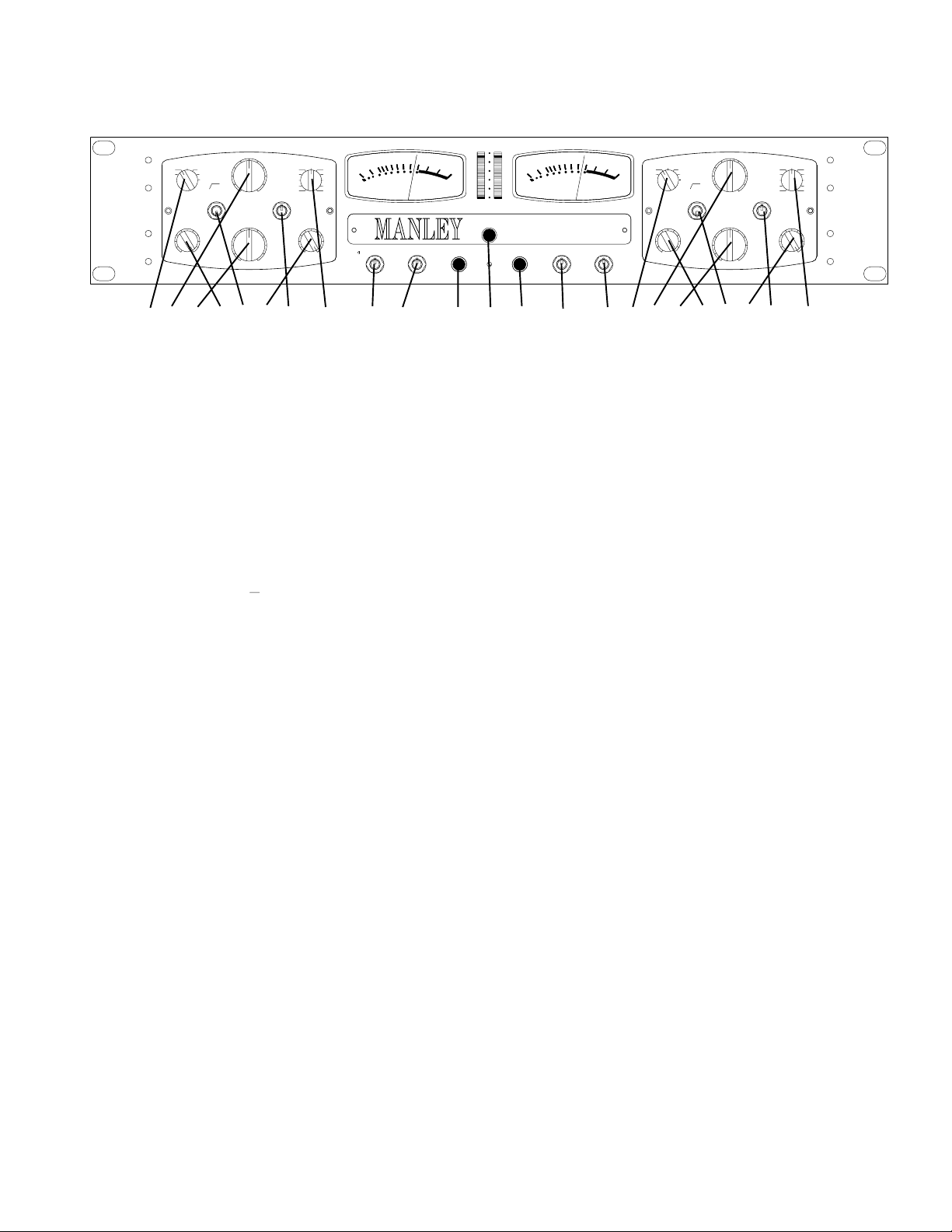
1)SOURCE: This is the Input Selector that you use to choose the input to the SLAM!. The choices are DAC (digital to analog converter
if this option is installed), LINE, DI, MIC, MIC ø (phase reverse), and MIC 100 HZ (high pass filter) which has a little graphic showing
the filter. LINE selects the BALANCED LINE INPUT Combo jack (XLR or 1/4") and is intended for +4 dBu signals, but by cranking the
INPUT level can be used with -10 dBv signals. DI selects the INSTRUMENT INPUT jack and routes it through the mic preamp for lots
of gain if needed. MIC also uses the BALANCED LINE Combo jack and routes it through the mic pre for 60 dB of gain (and another 20
dB by cranking the OUTPUT level). MIC ø is the same except opposite and just phase reversed (the proper term is polarity reversed). MIC
100 Hz is normal polarity but the lows below 100 hertz are filtered out which is useful on many vocals and overheads, to remove pops, air
conditioning rumble, etc.
2) INPUT: This is the first volume control and has about 60 dB of range for MIC and DI, and from -20 to +20 for LINE and DAC. For
LINE and DAC, the normal setting will be 12:00, or straight up, but this isn't the rule or an absolute calibration. For MIC or DI, the knob
might be anywhere depending on the mic, the loudness of the instrument, the distance, etc., and it might be prudent to turn the knob down
to start, rather than starting at 12:00.
3) OUTPUT: This is the final volume control and is used to set the output level to tape or disk, and as the 'gain make-up' after the Opto
Limiter, if you need to compare 'limit and bypass'. The FET Limiter senses the signal right at the output jack, so it acts as if it is a final limiter
after the OUTPUT level. Circuit-wise the FET Limiter is directly after the Opto, and before the OUTPUT level (but doesn't act like it) and
before the final tube gain stage/ line driver. The range of this knob is about -20 dB to +20 dB with unity gain near 12:00. Most of the time
it will live between 12:00 and 3:00.
4) OPTO LIMITER: A simple threshold knob for the OPTO limiter. Fully clockwise (+26) is 'out' and a good place to start. As you turn
this knob counter-clockwise, there is more likelyhood that limiting will happen. Some dynamics units have the threshold go one way and
some the other. On the SLAM!, all of the pots, should make the signal louder when turned clockwise, (except the RELEASE which is a
switch).
5) SC HZ: Side-Chain Hertz. This is a HP filter in the Opto Limiter side-chain that makes that limiter less sensitive to low frequencies.
It does not affect the FET Limiter. The filter helps minimise pumping and strange volume changes. Sometimes kick drums and bass seem
to 'trigger' too much limiting. The FLAT setting, bypasses the filter, 100 filters 100 Hz by 6 dB and more for frequencies below that.
Similarly 200 filters 200 Hz 6 dB and more below but also boosts about 4 dB at 6 kHz for gentle and subtle de-essing and can be considered
a vocal setting. Normally, 2 filters like these require one to change the threshold significantly, but these are compensated to minimise that.
6) FET LIMITER: Another simple threshold knob. One can blend any balance of Opto and FET limiters by using the two threshold
controls. Each limiter has its own character and advantages, and they complement each other, so that by using both, one can get most of
the advantages without the disadvantages. For example, the Opto can limit deeply, smoothly and has a high 'ratio', but is a little slow for
drums, while the FET Limiter can be very fast, but not as deep. The Opto has inherant time constants but the FET can be adjusted for attack
and release times. What the Opto misses, the FET should catch, depending on how you blend them and the FET ATTACK time.
7) ATTACK: This just affects the FET Limiter. With compressors, 'attack knobs' are used to set how fast the compressor responds and
pulls down a signal. Traditional limiters don't have this because it compromises the 'concept' of limiting if there is any overshoot. We
compromised somewhere between 'text-book limiter' and 'typical compressor', and simulated much of the 'sound' of the attack control while
still providing more transient reduction than is apparent. VF is very fast (.1 mS), F is fast (1mS) and M is moderate (10mS). VF is the best
if you need to prevent 'overs' and is closest to the traditional or text-book limiter. F and M tend to let more transient through but are also
more punchy and may be less detrimental to drums. Expect to adjust the FET LIMIT knob a bit for similar depths of reduction when you
change ATTACK (typical). There is another side-chain that grabs much of the peaks, almost inaudibly, but our ears tend to hear the sidechain that has the ATTACK and RELEASE knobs. Use your ears to determine the best setting. Instruments with fast transients like drums
show the biggest differences, vocals less so, and soft flute-like sounds may not be affected except for a little threshold difference.
10
Page 11

8) RELEASE: This only affects the FET Limiter. There are 11 positions numbered from 2 Seconds (slowest), to 10 milli-Seconds (fastest).
Slow releases tend to be the least audible and will be cleanest. Medium release times on the SLAM! are pretty fast for a limiter and where
the most loudness increase tends to be, but if pushed too far also might be obvious with pumping or a volume rise after the 'cresendo'. This
may also be near the edge of when 'modulation' starts to become audible, especially if there is a lot of bass energy in the signal. Achieving
maximum loudness cleanly is not automatic and might require a bit of play between threshold(s) release time and attack because it really
depends on the music. The SLAM! attempts to minimise all the negatives, pumping, modulation, loss of 'energy' that is typical for a limiter
with fast attack and release times because this is where the maximum loudness lives - but - this is dancing on the edge of a dangerous cliff.
The SLAM! release time can be set up for ridiculously fast releases (10 & 25 mS) that pretty much guarantee modulation distortion with
lows, which is most often undesirable but can be used as an effect and yet another paint brush. We might caution using ultra-fast release
times with bass instruments, but it can be fun on rude drums and blazing solos. There is also a CLIP setting, which introduces a FET clipper
that is fairly round like some low feedback tube circuits overdriven and is a bit reminiscent of speaker distortion. We wanted to provide
a psycho-acoustic memory of loud, and this is one way. The CLIP is best suited to enhance a moderately distorted guitar, of fatten a synth.
It is not intended to replace your Marshall, or amp simulator, but can often be used to take them a bit further.
9) STEREO LINK: A 3 position toggle. The center position disables stereo linking and is labelled DUAL MONO. All of Manley's previous
limiter/compressors provide a LINK switch and both L&R controls have to be used for proper operation. Meanwhile, most other
compressors just use the left side while the right side controls become useless. Enough people requested, for us to include this mode of
LINKing. This is the STEREO LINK or up position. Both ways have advantages. The modern 'left-side only' is convenient, easy and can
be clever especially on a plug-in. The problem is that almost all implementations mono the L&R, which means sounds that are hard right
or left are 6 dB less likely to trigger limiting than sounds down the center, and anything out-of-phase won't be seen by the limiter at all.
We think a proper 'mastering compressor' is supposed to react to the peak waveform of both the left and right equally, or stop the same peaks
that causes the A/D to clip. This is easy in digital, but in analog it requires the user to use both sides, and that the limiters react equally based
on whichever side has the loudest peak. So the SLAM! also has that mode "BOTH & EXT" or the down position. This mode is also used
for the back panel linking to other SLAM!s for surround projects. For recording instruments the STEREO LINK mode is fine but for serious
mastering the BOTH & EXT mode is usually best. No LINK of the CLIP functions because why have one side clip the other?
10) LED (meter): This switch controls the LED bar graph meter. In the center position is basically an PEAK display of the audio output.
The upper position is basically to display GR (Gain Reduction, especially the FET Limiter). The down position is a momentary switch that
RESETs the peak hold (clears the dot) and is used to select the LED meter MODE if held down for a few seconds. A full and complete
description of the LED Meter is on page 12. Suffice it to say here that it does a lot.
11) LIMIT LEFT: Push it in to engage both the OPTO Limiter and the FET Limiter and the OUTPUT level control and it lights up blue.
This is not a hard-wire bypass, nor can it be, on a Swiss Army Knife, that has multiple inputs and outputs, mic pre-amps, etc. A hard-wire
bypass on a mastering version is a bit more likely.
12) POWER: OK, we won't do a 300 word description of a power switch this time. Push it, it lights RED, and turns on the bulk of the
Outboard Power Supply, which has been on idle drawing almost zero current. (If it doesn't, remember that there is also a power switch on
the power supply that has to be turned on.) The VU meters should light up, and about 30 seconds later the MUTE relay disengages (to prevent
tube warm-up thumps) and audio should be available or rising gently. This box has a long warm-up time but should be stable in a minute
and very nice in 15 minutes. Power-down mutes immediately. This might be a concern in a live situation, plan accordingly.
If you are not using it for 8 hours, you might as well turn it off to save power bills and tube life. There is a school of thought that suggests
that the initial turn-on is the hardest on tubes, and shortens their life and to some degree that is true. From our experience, it all depends
on the individual tube and some last 30 years and some 30 seconds. If you are concerned with tube life and down-time, repairs etc, buy
a set of extra tubes and save yourself some panic when you least need it. Changing a tube is almost as easy as changing a light bulb and
once the top cover is removed should take 20 seconds (compare that to arepair needing the 'ol soldering iron).
13) LIMIT RIGHT: Just like 11, but for Channel 2. Push to engage limiting and the OUTPUT level.
14) VU: Selects the source for the VU meters. I/P (input) shows the level directly after the INPUT level pot and is a good place to set the
MIC-PRE gain or rough out operating levels. O/P (output) shows the output level appearing on the output jacks. GR shows the OPTO Gain
Reduction, but not the FET. Most Opto Limiters use a VU to display gain reduction. When the limiters are bypassed the VU drops to below
-20 which is not intended to imply extra hard limiting. The Opto can also be displayed on the LED meters, with an expected increase in
speed because the Vactrols in the Opto Limiter are faster than VUs.
15) VU ATTENUATE: One can also pad the VU's down by 3 or 6 dB which is especially useful if the client is in the room and eyeing
the VU needles pegged in the red. Mastering engineers need this because a final mix has a lower ratio of peak to average level, and probably
lower again after mastering. The SLAM! will tend to do that too. For individual tracks, we expect the 0 or no pad to be the most common
but it depends on the instrument and distorted guitars may few and moderate peaks, but some percussion has huge peaks. We suggest the
3 dB pad for most mastering, and allowing about 3-6 dB below digital full scale on the peak meters. Why? FIR filters usually need 1dB
to 2 dB of headroom, MPEG usually requires 4-6 dB, the mastering engineer needs some room to work. The 6 dB VU pad is a hint that
maybe this is project is 'hyper-compressed', especially if is still bending far into the red. It is nice for CD playback though.
11
Page 12

METERING
The SLAM! has some very comprehensive metering. If you skip
this section, you’ll be back here with the yellow highlighter pen,
once you start really using the box.
There are both LED bar graphs and standard VU meters, and
each can show a variety of information. Before proceeding
further, we should mention that any peak meters and VU meters
should look different with music and that they are intended for
different purposes. VU meters are deliberately slower, and are
mostly intended to represent apparent loudness much like the
way our ears work. LED peak meters are most often chosen when
very fast peak reading signals need to be represented. For
“standard” VU meters there is a long list of specs and
qualifications, from needle size, color and ballistics to meter size,
color and scaling. Most importantly, VUs have been around a
long time and most engineers find them easiest to interpret and
most valid for analog tape. Because peak meters are fast
compared to VUs, transients like drums will look louder than on
VUs, and this is a good thing if we are concerned with clipping
or digital recording.
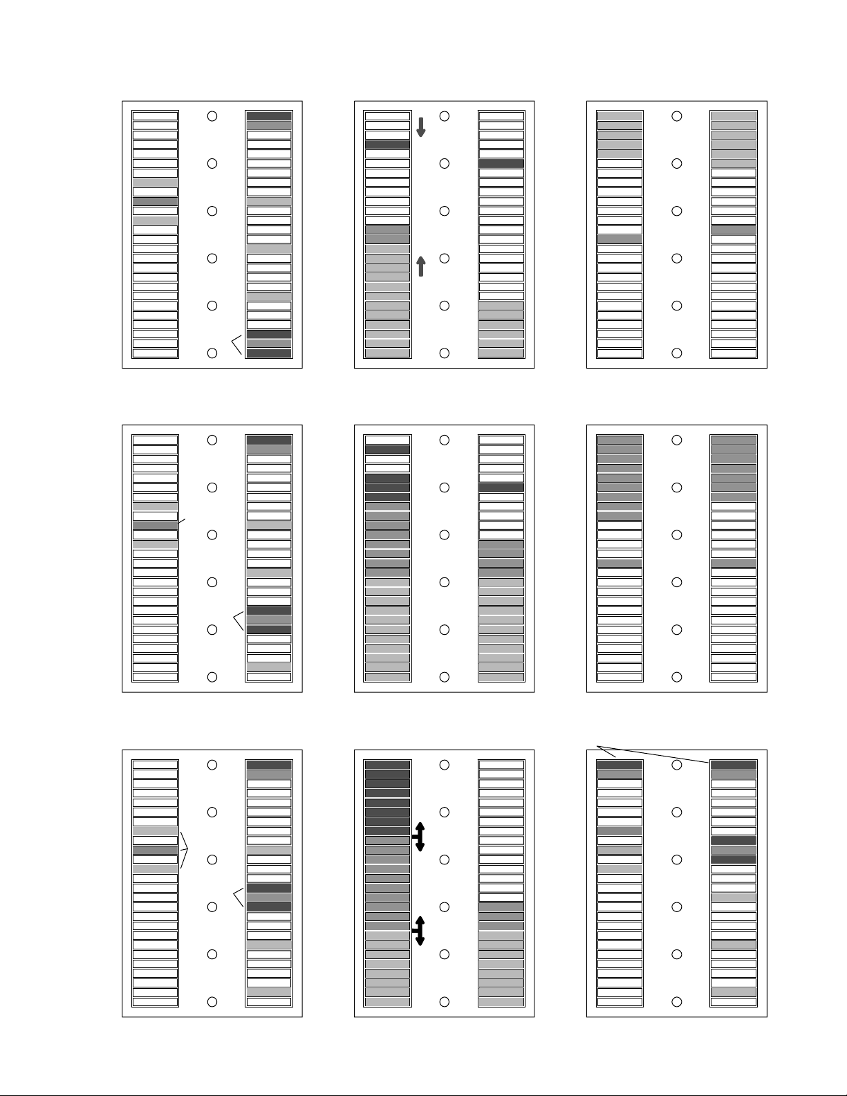
The LED bar graphs are multi-color (8), multi-mode (4), and
multi-purpose. The meter is controlled by a 3 position toggle
switch labeled LED, with MODE & RESET (down), PEAK
(middle) and GR (up). During normal operation, the switch will
be in the center or up position and will control the display on the
meters based on the currently selected mode. The momentary
down (spring) position has different functions depending on the
current operating mode and how long the switch is held down.
Holding the switch down for more than .5 seconds suspends
normal operation and enters the Mode Menu, indicated by a
colorful pulsing on the top 2 segments of the right meter. While
in this menu, one of 4 Modes described below can be selected.
The selected mode is shown by a lit segment surrounded by two
others near the bottom of the right meter. You can scroll through
the 4 modes by pushing the switch down again quickly (before it
returns to ‘normal’). Once the desired mode is lit, you ‘confirm’
the choice by either waiting 2.5 seconds or once again pushing
down the switch but longer than .5 seconds. Modes 1 and 2 are
the normal display modes and normal operation resumes. Modes
3 and 4 are used to select options.
Modes
MODE 1) DUAL DISPLAY: (shows two things at once)
Peak Position (center): Displays audio as a green and amber bar
from the bottom up. FET Gain reduction is simultaneously
displayed as a red dot from the top down.
GR Position (up): Displays FET Gain Reduction as a Green bar
from the top down and OPTO Gain reduction as an Orange dot
from the top down.
The Peak Hold dot and the third bar color are not available in this
‘dual display’ mode
In each mode ADC clipping is also displayed. In Mode 1 PEAK
the Green segments turn Red. In Mode 1 GR, the Green FET bar
turns Red. In Mode 2 you can have the Green turn Red or the top
2 segments turn bright Red depending on where the LED TRIM
is set.
MODE 2) SINGLE DISPLAY:
PEAK Position (center): This is a typical peak meter with a peak
hold dot. The bar is divided into 3 colors, Green, Amber & Red.
GR Position (up): Displays the sum of FET and OPTO Gain
Reduction (or the total limiting) from the top down. Both the
limiters are added together which may look a lot more drastic
than it sounds and some interpretation is required. It is most
useful when minimal limiting is the goal.
MODE 3) COLOR CHANGE POINTS:
You can change where the audio peak meters change color from
green to amber and from amber to red. This is an unusual feature
of this meter and lets you 'match' the SLAM!'s peak meter to the
meters on your digital recorder or work-station. The SLAM!
meters are analog and your other meters are very likely pure
digital so exact segment for segment matching is unlikely. This
just gives you a way to set color change points.
Select Mode 3 with the momentary toggle and the display will
change so that the left meter is totally lit and the right meter is
still in audio peak mode (for reference). Below the POWER
button is a small hole and a trim pot lives behind it. A small
screwdriver or tweaker is needed to adjust it. If the Mode Switch
is in the center position, then you can adjust the point where
green changes to amber. If the Mode switch is in the GR or up
position, you can change the amber to red point.
If you run out of range on the trim, exit Mode 3, tweak the trim
to approximately center, then go back to Mode 3 and set the color
change point where you want.
If you tweak the orange-red color change point to "over the top
of the display" (max), then the ADC clip indication for Mode 2
changes. Instead of the top 2 segments turning bright Red, all the
Green segments turn Red when the ADC clips at digital Full
Scale.
MODE 4) PEAK HOLD MENU
This is just for the peak hold dots in Mode 2. The selection is
displayed on the left LEDs.
a) No peaks held (no dot) (indicated by the lower of the 3 left
segments)
b) Peaks held for 1 second (typical generic peak meter)
(indicated by the middle of the 3 left segments)
c) 'Infinite' Hold, stores the peak until you manually reset by a
quick push down and release of the momentary toggle. This
mode is handy when the SLAM! is behind you and you need to
know after the fact, the loudest transient that went through.
Unfortunately, it won't hold a ADC clip indication.
RESET
Each time a mode is changed, all settings are saved to nonvolatile memory. If you find that you have 'out moded' yourself,
or that the meter is looking goofy, the factory default settings
can be restored as follows. With power off, press and hold the
LED Meter switch down, and turn the power on. The left meter
will light 2 segments red, the right green, release the switch.
Sometimes the Opto will cause a stuck segment because the opto
GR is not slowed down (shared from the VU meter GR mode).
Just change to Peak and back will clear the segments, or wait
until a the next hot peak clears it for you.
12
Page 13
TIMED
INFINITE
1 SEC.
NO HOLD
MODE1 SELECT
MENU DISPLAY
PEAK HOLD MODES
CURSOR
MODE 4
(PEAK
HOLD)
MODE 3
(COLOR
CHANGE)
MODE 2
(SINGLE)
MODE 1
(DUAL)
MODE 1PEAK Toggle Middle
Combination PEAK + FET GR
+26
FET GR
+21
+16
OUTPUT
LEVEL
+11
+5dBu
+4 dBu
+3 dBu
+2 dBu
+6
-6
MODE 1GR Toggle UP
Combination OPTO + FET GR
-1
-2
-3
FET GR
OPTO GR
-4
-6
-11
-16
-21
-26
-5
INFINITE
TIMED
1 SEC.
NO HOLD
MODE2 SELECT
MENU DISPLAY
SHOWING
'TIMED 1 SEC'
IS ACTIVE
CURSOR
MODE3 SELECT
MENU DISPLAY
MODE 4
(PEAK
HOLD)
MODE 3
(COLOR
CHANGE)
MODE 2
(SINGLE)
(DEFAULT)
MODE 1
(DUAL)
MODE 2 PEAK
PEAK + PEAK HOLD
PEAK HOLD
PEAK
+26
+21
+16
+11
+5dBu
+4 dBu
+3 dBu
+2 dBu
+6
-6
MODESELECT 3
COLOR CHANGE SET
RED
TOTALFET+OPTO & HOLD
AFTER 2 SECS
THESE TOP LEDS
ALTERNATE
INDICATING OK
TO SELECT ANY
PEAK HOLD DOT MODE
MODE 2 GR Toggle UP
TOTAL GR
FET +OPTO
ADDED
MAX GR
(peak hold)
MODE4 SELECT
PEAK HOLD TYPE
INFINITE
TIMED
1 SEC.
NO HOLD
PEAK HOLD
CURSOR
MODE 4
(PEAK
HOLD)
MODE 3
(COLOR
CHANGE)
MODE 2
(SINGLE)
MODE 1
(DUAL)
SET with
TOGGLE
in UP
position
AMBER
SET with
TOGGLE
in MIDDLE
position
USE'LED
TRIM' TO
SETCOLOR
GREEN
CHANGE
AUDIO
INFINITE
TIMED
1 SEC.
NO HOLD
THIS PAGE IS IN COLOR PDF FORMAT AT http://www.manleylabs.com/PDF/SLAM!%20meter.pdf
MODE 4
(PEAK
HOLD)
MODE 3
(COLOR
CHANGE)
MODE 2
(SINGLE)
MODE 1
(DUAL)
Page 14

VU METERS
Two toggles are used for the VU meters. One is used to select
whether the VUs display Input Level (after the Input Pot), Output
Level, or the OPTO Limiter Gain Reduction. If in BYPASS the
OPTO GR the meters drop out rather than sit on zero. A VU meter
showing OPTO GR seems to be a bit of a standard and the time
constants and ballistics are a good match, even if the VU does not
show every drop of gain reduction. The LED meter also can display
Opto GR or the total gain reduction.
The second toggle is a pad or attenuator for the VUs in the Input or
Output modes and has no effect on GR mode. The 3 position switch
gives 0 (no attenuation and calibrated to +4dBu), -3 dB and –6 dB.
While it is very unusual to get an attenuator for VU meters on
standard rack processors, it is a feature we have been building onto
mastering consoles for many years. A regular VU meter would be
continually pinned in the red without the attenuator (which may
have a disturbing effect on some clients). There are several reasons
for this, some pre-dating the trends of heavy squashing. Compare
individual acoustic tracks at DFS, to a mix at DFS, and the mix will
generally look hotter on the VUs. Mixes tend to have more average
energy than individual tracks. Both mixing engineers and mastering
engineers often (usually) compress a mix, which also increases the
ratio of average to peak somewhat. For example in recording,
typical peak to average ratios are 16 to 20 dB, but in mastering 14
dB or less.
The SLAM! is a Swiss Army Knife and is intended to be used for
much more than just mixes and mastering. Because it can severely
reduce the ratio of average to peak levels, and because most of us
now reference levels to digital full scale (a peak reading), it follows
that without the attenuator, the poor VUs would be ‘in the red’ much
of their life. We caution that the –6 position can mislead one into a
situation where the audio is really too hot, or too squashed. On
mastering consoles, the most often used VU pad is –4dB (a hint).
METERING GENERALLY
The VU meters and the SLAM! peak meters will never agree and
maybe the SLAM! peak meters are a little 'off' from the peak meters
on an external ADC or DAC. What is going on? Which ones do I
trust? How can I calibrate them to look the same?
These questions have been around for as long as there have been
meters. VUs should match well with other VUs because there is a
comprehensive list of standards and qualifications to meet to be a
true VU meter. Part of the specification are 'dynamic characteristics'
which describes "The pointer shall reach 99 on the percent scale on
0.3 second, overshoot less than 1.5% (.15dB)". This essentially
makes the VU meter act with "approximate RMS" response and our
ears have an "approximate RMS response". Ahhhhh loudness.
Peak Meters are much faster and are supposed to catch events less
than 0.0001 Sec (compared to the VU's .3 Sec) which means that
transients have a much bigger influence on peak meters. One
problem is that our eyes won't be able to adequately see a 0.1 mSec
flash or even 1 or 10 mSec so the designer has to stretch the duration
of the leds or pointer. In a sense, this exagerates transient contribution,
but at least looks good. There can also be a peak hold dot that adds
a digital stretch to the duration and allows us the luxury of blinking
or looking away once in a while. We have that in mode 2.
In pro audio there are few measurement standards (or even de-facto
standards) that exist and peak meter calibrations and digital converter
I/O levels are more prime examples. With digital peak meters that
are married to digital converters, one at least expects that an 'over'
in the A to D over would light the top red LED. Wrong - the better
meters use 4 samples over and the best allow that number to be user
set. 4 samples over is about the threshold of where we hear a clip.
Makes sense to me.
The SLAM! LED meter is not digital, it is an analog meter with a
micro-processor. It is not reading the AES-EBU data streams, and
just measures 6 analog inputs plus 1 signal from the optional A to D
(an over that's equivalent to 4 samples at 48K). It can be adjusted for
different analog sensitivities with an internal trim pot but this is not
guaranteed to 'match' other peak meters nor was it intended to. The
SLAM displays approximately 1 dB per segment, except near the
bottom which are much bigger steps to show signal present. Other
meters may show 2 dB or 1/2 dB steps or be dB scaled on a curve.
Our solution to allow some sort of matching with other peak meters
(like the ones on your favorite A to D), is to give you a way to set
where the color changes occur. The transition from green to amber
is settable, and for mode 2, also the transition from amber to red. This
can be done from the front panel without ever removing the unit
from the rack or unscrewing the top (mode 3).
In order to provide some useful indication of A to D clip or overs,
any green LEDS turn red, which is hard to miss. What is interesting,
is that because the meter is looking at analog levels, one can see how
many dBs the peak went beyond A to D clipping and this is also a
good indication of how audible the clip was.
So to answer the question "Which one should I trust?" the best
answer is "all of them with some interpretation and a grain of salt".
The VU is best to show apparent volume or apparent GR, the
SLAM! peak meters show analog peaks, headroom in the SLAM!,
and momentary GR that may or may not be audible, plus shows
optional internal A to D clipping. External digital peak meters on the
recording device should accurately display available headroom and
clipping there. None of them is 100% accurate, nor implicitly
perfect, and because each may have different response characteristics,
might look different especially after a peak and the rates that dots fall
and/or hold. If this is what you would like to calibrate, sorry.
Regarding calibrating exactly how many dBs it takes to hit digital
full scale on the A to D, we didn't (and couldn't) put a little trim pot
somewhere handy. Why not? The whole front panel is a bunch of
level controls or controls that affect level and there ain't no detents.
In other words this isn't just a basic A to D that does nothing else.
You don't have trim pots, you get a slew of big knobs and 4 limiters
to get optimum levels, but not finely calibrated. The other reason is
that the A to D front end is a transformer, not a bunch of op-amps.
For the DAC there are trims that can be used to calibrate the back
panel 1/4" balanced +4 dBm outputs. We set them so that DFS = 8.0
volts RMS (-16 dB from DFS = 1.27 volts or +4.3 dBm), which is
one common standard but there are others (-14 to -20). The DAC
signal is reduced 6 dB from the -16 DFS standard if you select the
DAC as the SLAM! input. With so many tracks and mixes squashed
these days, it allows a better sweet spot for the SLAM!. You can
always turn up the INPUT 6dB if you need. With the INPUT at 12:00
a -10 DFS should give 0VU and the 4th LED should light. DFS will
pin the VU and the LED will hit about half way up (LED #14).
14
Page 15

LIMITERS
"The FET Limiter"
The first compressors we know of used special tubes designed for
radio and gain control. These are the "remote cut-off" type like the
6386 as used in the Fairchild 670. Manley has been making the
"Variable MU" compressor/limiter for many years based on the
same principle.
Opto limiters probably began in the early 60's with the UREI LA2A
which used a small electro luminescent panel driven by audio
directly from a tube circuit. This panel was in a light shielded box
with a photo-resistor so that when the panel lit, the light shone on the
photo-resistor which in turn dropped in resistance and shunted audio
to ground, and reduced its level. Very simple but effective technique
which has stood the test of time. Part of the reason is the simplicity
of the 2 knob approach and part is the inherant attack and release
times both the electroluminescent panel and photo resistor have and
part is the sound of the tube/transformer circuits.
There weren't many companies building pro audio gear in the 60s
and 70s, but we had FET limiters, discrete transistor voltage controlled
amplifier (VCA) limiters, biased diode limiters and, in general, all
had plenty of color and distortion. One of the best known FET based
limiters is the UREI 1176 which brought more control to attack and
release times and had ratio switches. The first few generations of IC
based VCAs were also less than perfect, and VCAs got a bad name
but slowly improved over the years. With cheap easy to use op-amps
and VCAs, gear prices dropping, music business growing, we began
to see more gear but somehow the antique 670s and LA2As and
1176s were still in use and preferred.
In the early 90's a few maverick audio manufacturers including us
responded to that knowledge and developed new-old technologies.
Manley, for example began the ELOP using a LED/photo resistor
component called a Vactrol and combined it with ICs to drive it and
tube circuits for the audio. Over the years, that opto circuit was
revisited in a discrete transistor Langevin ELOP, variations on the
theme used in the VOXBOX and once again here in the SLAM!.
In developing the SLAM!, we began with the idea that probably we
could find alternate Vactrols that could be used to give some variety
to the opto-limiting. In the end, after trying every one out there, we
decided the one we had always used, was our favorite and the others
had more drawbacks than advantages. We did improve the drive and
metering electronics, and added a HP filter in the side-chain and
added the jacks to allow a user to insert their own EQ into the sidechain. In most aspects, the opto-limiter circuit is similar to the one
used in our previous Elop's and uses audio to drive the LEDs. This
means that we can't possibly adjust the attack and decay characteristics
significantly without changing Vactrols. On the other hand, this
mode of operation, seems to act more like an RMS responding
circuit and reacts to many sounds in a way that we prefer over opto's
with the conventional attack, release, etc controls and all the
complications that a gain control element with its own timing
characteristics adds to that recipe. To make a long story short, we
like what happens with that simple old-school approach. The
difference in driver circuits plus the side-chain filter does seem to
make the opto a lot more useful on mixes and drums than our
previous units. We also allow some fast LED metering of the opto
in addition to the regular VUs which helps show how fast it tends to
react and gives a more complete picture for critical applications.
Because we couldn't improve much on our old opto circuit we
decided to add a second 'type' of limiter with its own characteristics
and its own historical roots. Some early limiters like the 1176 used
FETs for the gain reduction element which offered much faster
attack times and controllable releases.
The problem with FETs when used as a gain control element is that
they can add unpleasant distortion unless the signal is very low (like
-30 to -40 dB) and we also wanted a few gain controls which also eat
signal unless they are cranked. Throwing op-amps around to get
gain where needed is easy, but not our style. Keeping to an all-tube
Class-A concept requires different approaches.
We took a novel approach and used a transformer as part of the shunt
circuit, which not only reduced the signal to a nice level for the FET
but allowed us to use a pair of FETs in counter-phase to reduce
distortion. An expensive approach but worth it.
Our main goal of the FET limiter was to achieve the fastest release
that we could cleanly. This is the quality that causes the gain to return
as fast as possible, which is what gives us our perception of
'loudness' .The goal here was a great 'go-louder' box. Fast attacks,
∞ : 1 brickwall limiting is important to prevent 'overs' but not for
and
increasing the average level. A very fast transient that gets through
will clip but as long as the duration is short enough it will not be
perceived as distortion. Very fast release times, unfortunately,
usually imply modulation distortion where the limiter traces the
waveform at low frequencies rather than the volume envelope. This
is inevitable, but we made it possible to achieve faster and cleaner
releases than usual. It can still get crunchy so be careful.
This FET sidechain uses several techniques to get those fast releases.
The usual full-wave rectifier was replaced with a quadrature rectifier
that uses 4 phases to determine peaks and allows twice as fast
smoothing. Then we combine multiple side-chains and the typical
exponential capacitor release was modified for linear decay rates.
All of this resulted in faster clean releases, thus more loudness. Still,
at the fastest release times it is quite possible to get modulation
distortion, which is sometimes a useful color and often a problem
with wide spectrum sounds like mixes or instruments with lots of
lows. Listen for a growly sounding distortion on faster release times.
The multiple side-chains also gave us the possibility of introducing
an attack switch, which is usually not found on a limiter (compressors,
yes). The attack switch works on the slowest side-chain, which gives
much of the audible familiarity of the control while the other sidechains are still biting the fastest transients. Like most attack controls,
as you go from fastest to slowest positions, you tend to lose some
threshold or limiting, so adjusting the FET LIMITER threshold will
probably be required, conversly more clockwise for VF settings.
A CLIP setting is on the release switch, that introduces a very
rounded clipping with a variable threshold. This type of distortion
is reminiscent of speaker distortion and tends to be mentally associated
with 'loud'. Of course, more conventional clipping is possible and
by turning up the INPUT, and turning down the OUTPUT, or if one
wants 'drastic' switching to MIC or INSTRUMENT will do that of
course. And, no, you won't hurt anything as long as, phantom is off,
and you prudently turned the OUTPUT down first. It wasn't designed
to simulate a guitar amp but intended to 'assist' an already overdriven
tone. Mostly CLIP is used to get a few extra dB of 'angry loud'.
15
Page 16

'Hyper-Compression'
Hints
The word 'Hyper-compression' is a word mastering engineers use
and was coined by Lynn Fuston (Mastering Web Board, DSD vs 96/
24). For many people it implies the idea of limiting and multi-band
limiting and normalizing and squeezing every last drop of apparent
volume possible onto a stereo mix but most mastering engineers
would prefer not to. It has become almost a contest and everybody
wants to be louder than everybody else. Record companies expect
it, or ask for it and sometimes demand it. Mastering engineers are
expected to do it and are given mixes so brutally squashed that they
can't get any louder anywhere without just clipping and distorting.
'Maximizing' level also implies 'minimizing' dynamics and transients.
Dynamics and transients are one of the few available 'elements' in
sound and music, with the others being pitch, duration and waveform.
Very primitive music was just log drums and stretched animal skins,
or mostly just transients and dynamics. It's not hard to make 'music'
with just transient information, but can you do it with just pitch (like
a technician's oscillator), or the one of the other two elements?
Dynamics and transients are musical elements and not the enemy.
Maximizing levels very often results in a CD that can exhaust the
listener before the first song is over. It can produce an aggressive inyour-face constant barrage that might not be appropriate for every
project, every song, and every artist. It might be like most effects,
best used as an effect and where it is appropriate, sometimes full tilt
and sometimes lightly. Super-squashing might also be going out of
fashion, and we see a trend where producers are avoiding it.
Maximizing is best done at the mastering stage rather than during
mixing, usually. We've heard these stories many times, "The A&R
guy (or producer or artist) demanded that the engineer use a certain
box to maximize the mix, so he did, but he also supplied the
mastering engineer with an alternative version without that box.
The mastering engineer did his best with both versions, and everybody
preferred the results from the 'raw' tape and hated the maximized
mix, and in the end the one from the 'raw' version was loudest
anyways". Never heard the opposite story. Why? Mastering engineers
generally have the best tools, the most tools, and right tools for the
job, and a 'pre-mastered' job often robs his or hers opportunity to
apply those tools, and experience, and abilities. If you do use the
SLAM! on a mix (before it gets professionally mastered) you should
have a version without it and/or a version with light limiting. They
also like 24bit masters, and a little headroom (like -3 to -6 dB below
digital clipping) and lots of accurate labels/notes. Thank us later.
Maximizing generally does not help the song sound any louder on
the radio or TV. Perhaps you know that they are old hands at that
game and have compressors, 10 band limiters, 4 band limiters, full
range limiters and clippers strapped across the audio chain all the
time and have had for 15 years. Everything comes out the same
volume - as loud as they can make it. Things can get silly because
their boxes were set to work on 'normal' mixes and sometimes they
get goofy when given super-squashed songs and songs that have lots
of stereo or out-of-phase info. For them, width is bad, mono is good,
it transmits further, gets bigger audience share, bigger ad bucks.Car
CD players like over-compressed material and many now build a
bad compressor into the car stereo, so this is covered too..
So, the SLAM! is another "GO-LOUDER" box, but with a warning
label. We are building guns, not pulling triggers. As always, use
your ears, judgement, and taste. Be careful with this cannon.
Everybody knows that you should make those A to D peak meters
go as hot as possible, digital full scale, but NEVER clip. Well, we
have two urban myths in that statement. Often enough, the next thing
after the A/D (filters, plug-ins, processors & EQs) requires a few dB
of headroom and they might have a nasty distortion complete with
aliasing if given digital full scale. It is caused by a little ripple in the
pass band of the filter that actually can add a little bumps across the
spectrum. The 'better' the filter the lower those bumps will be, but
they add up. Most filters need between 1 to 3 dB of headroom. Some
MPEG encoders need 6 dB. Don't feel compelled to hit DFS if you
are working 24 bit and going to master later. Resolution will be fine
and a little headroom may be a nice thing 6 dB below DFS. Save
almost DFS levels for mastering 16 bit/44.1 CDs that need every bit.
Yes, most early A/Ds sounded horrible when pushed into clipping
and clacked, barked and complained loudly. Most modern A/Ds can
be pushed a bit 'over' into clipping without obvious distortion and a
few (especially older Ultra-Analog based ones) have a pleasant clip.
You can certainly get a hotter mix, and more ballz with a little
clipping (keyword being little) but our advice is to choose where and
how to clip carefully. Usually analog clips better than digital and
usually tube units clip better than solid state, but lots of tube boxes
don't sound good at all clipping (including some of ours). So, it
requires experimentation, (on your time), careful level scaling, and
careful listening to highs, lows, peaks and noise. If you do it right,
maybe, make a master with level to rival the top mastering engineers,
or do it a bit wrong and ruin the project, and have something you
regret for a long time. It is not easy or automatic, and boxes that claim
to do it usually don't. The SLAM! A/D seems to clip nicely though.
A large part of the trick to getting a hot loud mix is to watch the VUs.
The idea is not to see how far the needle can bend to the right, but how
still and immobile you can get it and still have it sound like music.
Make that needle just sit there while mixing before you limit and then
you just need to use a few dB of limiting and loud it will be. This is
not so easy to do. Limiting individual tracks and sub-groups makes
it easier. Start with the hottest tracks, which are usually vocals, bass
and drums. This applies for basic limiters, multi-band limiters and
de-essers. Each of these are harder to use effectively on a mix than
an individual track or sub-group. On a mix, anything hot can trigger
them and they affect everything. If you de-ess a mix, try not to mess
up high hats, acoustic guitars & careful EQ settings. De-essing a lead
vocal is relatively easy. Limiting a mix will probably seem to affect
the drums first, because in a typical mix drums are the source of most
of the transient spikes. The initial attack or transient gets pulled
down (spikes you probably liked during tracking) but also everything
else gets pulled down for that instant. So drums begin to sound more
distant and feel pulled back in the mix (and you spent an hour fine
tuning that part of the blend), they begin to sound dull (because the
transient contains the bulk of their highs), and reverbs and room mics
seem to get louder. When limiting hits vocals, some good things and
some questionable things can happen. Plosives (Ps, Bs Ds Ks) might
get hit and alter carefully sung pronuciations, but sometimes, after
EQ, plosives need some taming. Some singers hit high notes a lot
harder, and fader-riding, compressors or limiters are needed
(hopefully, in that order). In the end, if individual tracks and subgroups are limited first, then, not only is final limiting and mastering
easier, but also it is easier to mix, as well as to create dynamics in the
mix. By the way, vintage recordings rarely used a buss compressor
- its a fairly new trend. If you do limit the 2 buss, watch out for quiet
sections and the drum balance in the mix, and use those ears.
16
Page 17

Which brings up the first thing last. The traditional way to have
loudness, dynamics, excitement and smoothness all at the same
time is with that old tool called 'arranging'. Take another listen to
your favorite records and check out how they use many instruments
to create loud or a few to create quiet or a relief. Listen to how solos
& intro instruments sound great when not covered by everything
else. If it happens to be a recording of great musicians playing
together, listen to how they are their own automatic level control.
This rarely happens with a mostly overdubbed song, but sometimes
a great mix simulates it. Dynamics galore, but a constant level,
hmmmmm.
OPTIMUM SETTINGS
Sorry, we can't really tell you where to set the knobs for female
vocals, a strat, or next year's standard mastering level. It all depends
on the track and taste and the sound you are trying to achieve. We
can give you a few guidelines and share some experience, if that
helps.
Limiting can be more audible or difficult than on a well set up
compressor given the same number of dBs of gain reduction. This
is because limiting has a higher ratio and typically has faster attacks
and releases. Old school engineers advise "to only limit a few dB on
occasional peaks", and this is good advice on most limiters. Hopefully,
you will be able to limit a little deeper with the SLAM! without the
usual problems. A limiter that shows, say, 5 dBs of reduction, can
sound louder than a compressor set for 1:1.5 ratio and dropping 10
dB almost steadily. Certainly during quiet passages, the compressor
will seem louder, but the limiter can seem louder in the hotter
passages when it is just grabbing transient peaks. The compressor
might be smoother and more tolerant of settings, but won't offer the
protection and 'drive' of a well set up limiter. The compressor's job
is to reduce the difference between soft and loud in a smooth even
way. The limiter's job is to inaudibly stomp on the hottest transients,
and prevent peaks from getting above a set threshold. It's all in the
names.
How can you tell when you have it set wrong and set right? There
is no 'wrong or right' that applies to every day, but we can suggest
the usual things an engineer listens for. You should experiment with
some drastic settings when you are alone or can without scaring a
client. There are 3 main things and the amount of reduction affects
each of them, so it is worth trying some heavy-handed settings to
imprint the symptoms to your audio memory.
The first is modulation distortion. When a limiter is set for dangerously
fast releases, the bass waveform gets into the sidechain, causing the
gain of everything to be changed on a low frequency cycle by cycle
basis. The result is a ratty sort of distortion, not really bright and
edgy like clipping, but usually not very pretty either, and often not
very useful creatively. With the SLAM!'s FET limiter, you can
easily set releases that are way too fast and cause modulation if there
are any significant lows in the signal. The cure is slower releases,
less limiting and/or slower attacks. Settings slower than 100mS are
generally pretty safe but always listen.
With the Opto, modulation can happen with about 10 dB or more
limiting on bass. You can use less limiting or try the side-chain filter
switch. Keep in mind that the side-chain filter will prevent some
limiting of loud low notes so there is a some risk of 'overs'. The
combination of both the Opto & FET can help share the load for
tougher signals like mixes and can be a sweet combination.
The second typical problem setting for limiters and maybe even
more for the SLAM! is pumping. The worst case scenario is a mix
that has a very hot transient followed by a significanty quieter few
seconds. A limiter should grab the peak, shove the gain down
sufficiently, then gradually return to normal gain. How gradually
depends on where you set the release. If the limiter was set so that
it reduced 20 dB, then that quiet passage may rise in level 20 dB over
a short time. This can sound pretty wierd depending on that quiet
passage. Unfortunately, some of the moderate release times, like
between 100mS and 500mS can be most obvious. Unfortunate
because, these are typically optimal settings for loudness
enhancement. Faster releases might distort and slower might tend to
hold the gain down or sit between peaks or beats. We have known
a few engineers to change release times on the fly, for transitions
between big chorusses and sparse verses that follow, and this can
work better than any electronic or algorithmic 'auto' setting.
The third problem is not really so bad unless you are attempting to
make the song loud. Releases set too long. When the release is very
long, a transient, however brief, triggers gain reduction, and a bar
later the gain is beginning to rise back to normal, and boom, another
transient reduces the level again. You could have turned down a
fader or final gain control and gotten the same effect. The SLAM!
isn't immune to this, but the slowest release is moderate at 2 seconds.
Some limiters have much longer releases. 8 second releases tend to
be safe and almost inaudible, but pulling a fader down a few dB
before the song starts is very, very inaudible and does about the same
thing. Sometimes the best thing, is to ride the fader, slowly, gently,
then add the limiter for what it does best - extremely fast reaction.
Vocals can be a prime candidate for limiting. Perhaps the most used
limiter ever for pop vocals is the vintage LA2A. The ELOP Limiter
in the SLAM! recreates that action, and goes a few steps further with
side-chain filters and FET limiter. Start with the ELOP typically on
the 100 SC filter (or 200 if esses need a bit of extra taming), get the
INPUT & ELOP LIMITER levels optimum, adjust for an optimum
level to 'tape'. Then maybe sneak in a bit of FET Limiting, with
Attack at VF, RELEASE between 1 sec and 100 mS.
For a Mix, we generally lean on the FET Limiter for most of the work.
Releases again between 1 sec and .1s are OK, but .1s is verging on
dangerous. Attack will be important. VF attacks will sound cleanest
but less punchy. Adjust to taste and watch out for loss of drums at
VF and distortion at M. Adding some ELOP will be subtle if more
than 6 dB of FET limiting is used. We suggest using the 200 SC filter
to tame highs and de-ess sometimes.
Guitars may like the FET CLIP setting for a bit of extra crunch. Bass
may require slow releases, and VF attacks for ultra clean sounds, but
for extra growl, there are quite a few settings that go there. Faster
releases, deeper limiting, and slower attacks each contribute to
various distortions, not to mention just overdriving levels. Piano is
difficult usually, but try faster attacks, slower releases and not too
much limiting.
Drums - well, you just gotta play with the SLAM! to find the most
appropriate sound. You can certainly tame dynamics, exagerate
room sound, crunch and mangle. Faster release times bring out the
room sound and ambiance. It's a bit drastic, but you can use one side
of the SLAM! for mic-pre and limiting, go out to an EQ, and return
to the other channel for yet more limiting, drive and A/D conversion.
You might record that first channel as a minimally processed backup too. Save something for the mix.
17
Page 18

Limiting and more limiting and more...
The following is a small section of the Orban Optimod-FM, 8400
owner's manual. This is a compressor used by radio stations before
they broadcast the music signal. Orban is, by far, the leading
company building broadcast limiters in the world. This eloquent
piece posted on <rec.audio.pro> by Robert Orban serves as yet
another warning for those that intend to use hyper-compression on
their mix.
At this writing, there has been a very disturbing trend in CD
mastering to apply levels of audio processing to CDs formerly
only used by “aggressively-processed” radio stations. These CDs
are audibly distorted (sometimes blatantly so) before any further
Optimod processing. The result of 8400 processing can be to
exaggerate this distortion and make these recordings noticeably
unpleasant to listen to over the air.
There is very little that a radio station can do with these CDs other
than to use conservative 8400 presets, which will cause loudness
loss that may be undesired in competitive markets. There is a
myth in the record industry that applying “radio-style” processing
to CDs in mastering will cause them to be louder or will reduce the
audible effects of on-air processing. In fact, the opposite is true:
these CDs will not be louder on air, but they will be audibly
distorted and unpleasant to listen to, lacking punch and clarity.
Another unfortunate trend is the tendency to put so much high
frequency energy on the CDs that this cannot possibly survive the
FM pre-emphasis/de-emphasis process. Although the 8400 loses
less high frequency energy than any previous Orban processor
(due to improvements in high frequency limiting and clipping
technology), it is nevertheless no match for CDs that are mastered
so bright that they will curl the vinyl off car dashboards.
We hope that the record industry will come to its senses when it
hears the consequences of these practices on the air. Alas, at this
writing, they have shown no signs of doing so.
Anyone—please feel free to quote anything I’ve posted on the
board. I am trying to bridge the broadcasting and mastering
communities, and the best way is to “get the word out.”
This subject has suddenly heated up on the Broadcast.net radiotech mailing list. Broadcast engineers have become very
concerned about the clipped and distorted material that they are
being presented with. In fact, one well-respected poster went so
far as to propose a minimum peak-to-average ratio spec for
material that was to be considered “broadcast quality,” and
proposed that stations reject any material breaking this spec.
The consensus was that radio stations need “radio-mastered”
mixes. These can have all of the EQ and compression applied to
the standard release, but need to have the peak limiting and
clipping greatly backed off or eliminated. This will retain the flavor
added by the mastering, but not the distortion!
In this age of broadband Internet connections, it would be
perfectly feasible to service stations with “radio-mastered” singles
from a password-protected website. Most stations would prefer
uncompressed files to retain quality and prevent any issues with
“dueling algorithms,” as stations often compress later on in the
chain, either when they store the material to hard disk for on-air
playback, or in their studio-to-transmitter links (STLs).
http://www.orban.com/
We completely agree with Robert's post and the suggestion to create
a few masters with lesser amounts of limiting. Hopefully the
password protected web-site can become available and producers
and/or record companies can post optimized mixes for radio.
Perhaps Robert's post was aimed more at the abuse of multi-band
limiters, but the SLAM! can be made to hyper-compress, and/or
distort which may cause problems further down the chain than just
the basic CD intended for home listening. It is just not that simple.
For example, one might clip a track deliberately for a certain effect
or for apparent loudness. If during the song, a section has less highs,
a station's multi-band limiter may try to lift the HF bands, exagerating
the HF harmonic distortion and making it more than ugly. In fact, it
might make it un-playable by some stations.
What might we suggest? Musicians might try to play at consistant
volumes. Mix engineers might limit individual tracks and subgroups more than the mix. They might also want to rely more on the
mastering engineer for final limiting, and their expertise and
experience with how product translates to broadcasting. Mastering
engineers have to consider the broadcast chains. A&R people have
to realize that songs sell records, and a louder CD won't make much
difference. In fact, a CD that is too loud, too aggressive, too in-your
-face may also be too exhausting to listen to for more than one or two
songs - but A&R guys don't read manuals like this.
In more direct practical terms, run the mix 3 times and create 3
versions with different depths of limiting. This gives the mastering
engineer more to work with. The mastering engineer can aslso do the
same thing and create 3 masters. Then the only trick is making sure
the right parties get the right version, without misdirection.
Another idea mentioned earlier is limiting individual tracks, and
sub-groups. One can also create loudness just in how tracks are
mixed and EQ'ed. In fact, absolutely great mixes need very little or
nothing done in mastering (everybody's elusive goal). The worst
mixes need the most processing. Slapping a drastic processor on a
bad mix is just that, and doesn't make it a great mix or make real
mixing easier or 'mixing' something that everybody can do as long
as they have that drastic processor. Just gotta mix well first.
Perhaps the best advice is to do what experienced engineers have
done for 50 years with limiters. Use them gently and carefully. A few
dB may be better than none, and better than 10 dB of limiting. This,
of course, means you have to use your ears and meters and not
presets. The idea is not how much limiting you can get away with,
but how much and how little is optimum and still sounds good. The
usual answer is 2-6 dB on a mix (assuming fast attack time only).
In simple quick comparisons, we generally tend to prefer the choice
that is louder and most people can be fooled into thinking X is 'better'
than Y even with a fraction of a dB more volume. This is really one
place where a bit of extended listening is required to determine
which is actually better to listen to for any longer duration. Transients
and dynamics can be very nice too.
Maybe you were just thinking, how much (or little, right) should you
limit the mix for the mastering engineer. So now you have to
consider how much limiting is appropriate for the artist and song,
how much is appropriate for the CD and that audience and how much
is appropriate for radio, for the label, for vinyl dance tracks..... If
only one version is allowed - be careful, avoid regrettable squash.
18
Page 19

Digital Converters
The Quantum Converters
There is a lot of discussion on internet bulletin boards regarding bit
depth, sample rates, human hearing, dither, jitter and word clocks.
Many people claim to hear a difference between 48K, 96K and 192K
and those that percieve those differences seem to generally prefer
192K. Some don't hear the difference. Yours truly has listened to
digital for many years, and hosted big A/D and D/A shoot-outs and
heard various jitter effects and all the subtle differences between
most converters - but - it wasn't until comparing the SLAM!'s DAC
to 'conventional' DACs with CDs that a particular problem with
those conventional DACs became obvious. The SLAM! DAC was
'faster', and had way better imaging and depth while our conventional
DACs sounded slurred, drums were un-focussed, and more effort
was required to hear details and mix values. Not quite subtle.
After many hours (weeks) of rigorous calibrated A/B and A/B/X
comparisons it became clear that conventional DACs have a ramped
-up effect on transients, especially obvious on big bangs out of a
black background. In 15 years of listening to digital, I had never
noticed this effect, nor had seen any article, heard any discussion,
nor had it been suggested to listen for it. With more listening, it
became obvious that this effect messes up imaging width and depth
& groove or feel. It adds to the harshness of digital and could be a
major cause of 'digititus'. Hell, even tapping ones foot to the music,
or just enjoying the music was a little more difficult with conventional
DACs. We started out calling the effect pre-echo but settled on
'time-smear' as months wore on. There is no official and universally
accepted name for this effect. Then came the hard part. What is the
cause, who has researched this, why haven't we been told? The cause
is half easy and half incredibly difficult. It is easy to demonstrate that
the problem is caused by digital brick-wall FIR filters, because one
can readily hear the differences as filters are shifted higher and/or
made less steep. The difficult and frustrating part is that nobody
seems to know why we hear the filters. According to the theories that
digital designers live by and our present knowledge of human
hearing, we shouldn't be able to hear the difference between a FIR
with a 45K corner frequency and one with a 90K corner frequency
or one with a more gentle 90K slope - but we do, or at least those who
listen do. Pay attention to the leading edge of drums and percussion.
Further discussions with a variety of digital gurus, all seemed to
indicate, that they are aware of the 'time-smear' but also have no
solid scientific reason for why we hear it. Occasionally somebody
with interests in not discussing time-smear will mention "the FIR
impulse response ripples are at 22K or higher and we don't hear
that". OK, but we DO hear the FIRs all the same. Maybe distortion
in tweeters and electronics is a factor and maybe not. Nobody
mentioned jitter years ago until help arrived. I don't know why we
hear the FIRs either, but because we consider the problem to be very
significant for music, we think that you should know it exists and
that you should be concerned too. 'Groove' and 'feel' are kind of
important in music and time-smear doesn't ever help.
FIR filters have compelling advantages, but perhaps inherant
problems that a few expensive converters have minimized. The
good news is that a lot of CDs that we blamed mastering or digital
for sounding bad, come back to life. Also good news is that timesmear may be reduced to acceptible levels at 192K sample rates (and
48K data rates with SLAM!'s converters). In fact, the SLAM!'s
converters have less time smear than other converters running at
192K and are probably the first with this kind of timing performance
near this price range.
When we decided to offer digital converters, the idea was to provide
a convenient method to 'insert analog' into a digital studio. Part of the
goal was to avoid Phase Lock Loops (PLL's) to recover and clean up
the clock signal encoded in AES data streams. Two reasons for this:
we feel that most PLLs in use are truly inadequate and it requires a
great deal of work, time and intelligence to design a PLL fine enough
for 24bit audio. If a converter improves sonically by using a word
clock input, this is an indication that the clock recovery is insufficient
and that jitter has been audibly attenuated but most likely still a
problem. Then we met a new company with a better answer.
The converters in the SLAM! were were co-developed by a group
of very clever engineers in Switzerland called Anagram Technologies
along with bits from us. Anagram mostly design converters for hifi companies like Manley, Nagra, Audio Aero, Camelot-Tech and
Talk Electronics. "Anagram Technology DSP filters seem to be the
hot new numbers in the digital world", (Stereophile, Apr 2002).
Anagram had developed probably the best Asynchronous Sample
Rate Converter based on software running in a high speed SHARC
DSP chip. The process essentially eliminates jitter and provides the
best audible aspects of 192K converters at sensible data rates like
48 or 96K. We can't claim zero jitter, but it's damn close and difficult
to measure. The jitter is lower than most converters' internal crystals.
The DSP process borrows concepts from quantum physics. Quantum
Theory says we can never know both the mass and energy (speed)
of sub-atomic particles at the same time. In digital audio with any
amount of assumed jitter, likewise, there is always some uncertainty
of the actual sample value because we are unsure of the clock. What
makes Anagram's process unique is that both data and clock are
treated as a linked pair, and treated with parallel algorithms. Thus
the name and a hint of how jitter can be eliminated in software.
In our research and with input from Bob Katz, it became obvious that
besides jitter and analog audio implementation, that some of the
biggest differences between converters was due to the filters - both
the digital and analog varieties. This is why you have 3 choices for
both the ADC and DAC. It is unlikely that we can hear beyond 20K
or 25K but there do seem to be differences caused by ultra-sonic
noise and stray signals that may affect 20-20K audio. Some digital
filters and all analog filters, even with 80K 3dB points will create
some phase shift within the audio band. This is usually somewhere
between subtle and inaudible and may even be desireable. We might
prefer the 20K filters when we want some tape-like emulation
(especially the DAC) or just 'smooth'. There are also situations when
one needs a 20K filter to prevent problems further down the digital
chain. Some plug-ins or data-compression algorithms are known to
to misbehave with ultra-sonic harmonics or noise. 80K is flattest.
The combination of the SLAM! and Quantum was not intended to
be the absolute in clinical or sterile conversion. There was some
effort to make these into "warm converters" (hot, even). There are
no ICs or op-amps from the XLR input to the ADC just class-A low
distortion tube circuits. In fact, the input stage of the ADC is totally
passive; just a transformer (the warmth), a few inductors and
capacitors. With 192K sampling for speedy transients, tubes and
iron for the "phat", and limiters for color and ballz, it all should be
fun & useful and provide 'personality'. These converters may be
even cleaner, crisper and more accurate than most too. You'll just
have to compare them to find out.
19
Page 20

Here is another great post from Robert Orban dealing with an
esoteric audio topic that we also feel is very important, especially in
its relevance to brick wall anti-alias filters found in digital converters.
This was originally a 2 part post in rec.audio.pro that Robert editted
for the 'mastering forum' discussing digital EQ, etc: (9/17/2000)
Regarding the ability to “undo” IIR equalization: Provided that
the original IIR EQ is “minimum phase” (it means that all of the
z-plane zeros are within the unit circle, and is nearly always
true with conventional IIR eq), then a second pass where the
z-plane poles and zeros are swapped will completely undo
both the amplitude and phase changes caused by the first
pass. This will occur with arbitrary accuracy, limited only by
the bit depth of the arithmetic used to implement the filters.
The math is very simple:
A*(N/D)*(D/N) = A, where
A is the original signal
(N/D) is the z transform of the first-pass IIR filter, and
(D/N) is the z transform of the second-pass IIR filter, which
is the inverse of the first-pass filter.
In fact, it is substantially harder to undo FIR equalization of
the linear phase persuasion, because this is non-minimumphase (there are zeros outside the unit circle in the z-plane),
so a stable inverse filter does _not_ exist.
Further, FIR filters “mess up the transient response” too.
They just do so in a different way. The tap weights of the FIR
_define_ the impulse response of the filter. If you design the
filter to be linear phase, then the impulse response is
symmetrical around its center, and the part of the impulse
response containing significant energy is generally _longer_
than the impulse response of a minimum-phase IIR filter with
the same amplitude response as the FIR.
Further, the FIR impulse response will have pre-echo because
of its symmetry. The ear has much less ability to do temporal
masking of signals occurring _before_ the main energy lobe
of a transient than after. So the FIR’s pre-echo is much more
likely to be audible on transient material than the impulse
response of a minimum-phase IIR filter, where the impulse
response occurs _after_ the main energy lobe, and is shorter
(not counting the effects of the truncation of the FIR impulse
response at its ends).
In fact, the pre-echo of linear-phase FIR filter banks causes
notorious problems in the design of perceptual encoders.
Advanced coders have to adaptively switch filters depending
on the transient content of the program material in order to
suppress the audible effects of the pre-echoes. Castanets
are a standard means for testing the audibility of this
problem.
“Group delay,” unless constant with frequency, HAS NO
INTUITIVE PHYSICAL MEANING. (Mathematically, it is the
negative of the first derivative of the phase with respect to
frequency.)
It _certainly_ does not measure the “time delay” of a given
frequency. For example, most minimum-phase highpass filters
have _negative_ group delay in certainly frequency ranges.
Does this mean that their outputs emerge before their inputs
have been applied? Of course not.
In short, it is NOT USEFUL to talk about non-constant group
delay as if it had any relationship to time delay through a filter.
Further, there is a lot of careful academic research around
that indicates that the magnitude response of a given filter
is several orders of magnitude more audible that its group
delay response. People keep saying the one equalizer sounds
different from another because it has “phase shift.” But just
saying it over and over does not make it so.
Further...in the world of linear mathematics, time response
and frequency response are _uniquely_ related. If you know
the magnitude and phase response of a filter at all frequencies,
you can compute the time response. Conversely, if you know
the impulse response, you can compute the magnitude and
phase response.
This is where you have to be careful. A non-trivial linear-phase
filter (like a symmetrical FIR filter) has an impulse response
that is SPREAD OUT OVER TIME. The fact that the filter is
linear-phase DOES NOT MATTER. It STILL spreads energy out
over time. ALL filters “time-smear” their input signals—it is
literally how they work. They just do so in different ways.
Minimum-phase filters (like most IIR filters) and linear-phase
filters (like symmetrical FIR filters) have impulse responses
that are shaped very differently. The peak energy in the
impulse response of a minimum-phase filter is asymmetric in
time. The majority of the energy occurs right at the attack
point, and the energy trails out after that.
In contrast, linear-phase impulse response is symmetrical in
time, which means that they have a pre-echo exactly equal
to the post-echo.
We can either hand-wave about “phase shift errors,” or we
can refer to actual psychoacoustics. In psychoacoustics,
there is a phenomenon called “temporal masking,” which
means the degree to which the ear is desensitized to energy
occurring before and after a “masker,” which is a dominant
sound that “drowns out” other quieter sounds.
It just so happens that temporal masking is NOT symmetrical
in time. The ear has a much poorer ability to mask sounds
occurring _before_ the masker (like the pre-echo of an FIR
impulse response) than it is able to mask sounds occurring
_after_ the masker. So there is at one argument, based on
psychoacoustics, that indicates that a linear-phase filter, by
creating pre-echoes in its impulse response, is actually
_more_ likely to create audible artifacts that an minimumphase filter, which does not create pre-echoes.
Further, this is not just theory — it’s a well-known and very
serious problem in the design of lossy codecs like the beloved
MP3. Good codec designs have to take fairly heroic measures
(usually changing the characteristics of their filter banks
depending on whether a sound is “impulsive” or not) to
suppress the audible effects of the pre-echoes.
My point?
People in pro audio tend to throw around the term “phase
shift” without being at all careful. If you hear something
different in the sound of two filters, chances are you are
hearing differences in the shape of the magnitude response
curve, not “phase shift” effects.
And be very careful when assuming that “linear phase” is a
Good Thing in filters. It is, in fact, a pretty unnatural sound.
Most natural frequency-selective phenomena (like mechanical
responses) do _not_ have pre-echoes.
Page 21
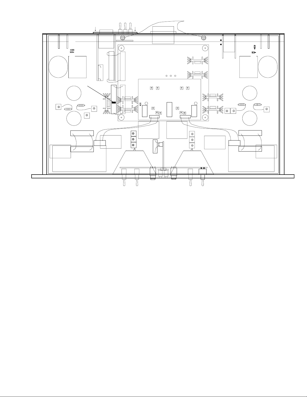
XLR
PIN 1
CIRCUIT
GND
CHASSIS
GND
TRANS
PARA
BREAK
BREAK
PARA
CHASSIS
GND
XLR
PIN 1
CIRCUIT
GND
TRANS
6414
12AT7
STEREO LINK=
LEFT SIDE(SUM)
SIDECHAIN BOARD
6414
12AT7
LED LOGIC
CONTROL BOARD T&B
CONTROL BOARD T&B
LINE AMP BIAS
LINE AMP GAIN
MIC AMP BIAS THD
OPTO GR
METER GR
ZERO
FET METER
AUDIO PEAK
FET
BIAS
BAL
GR
ZERO
METER GR
OPTO GR
MIC AMP BIAS
LINE AMP BIAS
LINE AMP GAIN
FET
FET METER
AUDIO PEAK
BIAS
BAL
GR
MIC
TRANSFORMER
FET
GR
TRANSFORMER
MIC
TRANSFORMER
3.3V D
BAL LINE OP
TRANSFORMER
30uF/200V
MULTICAP
22K
120-140VDC
140-170VDC
LINE
TRANSFORMER
TRANSFORMER
5V A
5V D
LINE
TRANSFORMER
FET
GR
-18V
+18V
+18V
-18V
300V LED
+/-18V LED
5V LED
AUDIO
SIDE CHAIN
BAL LINE OP
TRANSFORMER
30uF/200V
MULTICAP
REMOVE THESE
2 SCREWS. TOP
SLIDES BACK
22K
140-170VDC
120-140VDC
CHASSIS GND
CIRCUIT GND
ANAGRAM QUANTUM
DIGITAL CONVERTER
DAC AMPS
22K
22K
THE GUTS
REMOVE THESE
2 SCREWS. TOP
SLIDES BACK
GND
GND
PIN 1
XLR
CIRCUIT
CHASSIS
PARA
TRANS
BREAK
30uF/200V
MULTICAP
REMOVE THIS JUMPER
BEFORE INSTALLING A/D/A
BAL LINE OP
TRANSFORMER
6414
120-140VDC
MIC AMP BIAS
MIC
TRANSFORMER
CONTROL BOARD T&B
22K
12AT7
140-170VDC
22K
LINE AMP GAIN
1
1
DAC AMPS
LINE AMP BIAS
3.3V D
FET
GR
1
TRANSFORMER
ANAGRAM QUANTUM
DIGITAL CONVERTER
5V A
5V D
FET
BIAS
BAL
GR
SIDECHAIN BOARD
AUDIO PEAK
STEREO LINK=
LEFT SIDE(SUM)
ZERO
OPTO GR
LINE
TRANSFORMER
FET METER
METER GR
1
300V LED
+/-18V LED
5V LED
ZERO
LINE
TRANSFORMER
LED LOGIC
AUDIO PEAK
OPTO GR
1
FET METER
METER GR
FET
+18V
AUDIO
-18V
BIAS
BAL
GR
CHASSIS GND
CIRCUIT GND
+18V
SIDE CHAIN
-18V
FET
GR
TRANSFORMER
CHASSIS
XLR
CIRCUIT
BAL LINE OP
TRANSFORMER
6414
140-170VDC
LINE AMP BIAS
LINE AMP GAIN
22K
12AT7
1
1
1
CONTROL BOARD T&B
GND
PIN 1
GND
PARA
BREAK
TRANS
120-140VDC
22K
MIC
TRANSFORMER
30uF/200V
MULTICAP
MIC AMP BIAS THD
1) To Open: Disconnect the AC Power cable, let sit 15 minutes to allow the power supply capacitors to discharge. Remember
there are high voltages (350VDC) used in the SLAM! and that the capacitors may continue to hold a charge after AC power
and/or power supply connector is removed - Remove the two Philips Machine screws located on the perforated top cover
(towards the back). Slide the top cover out towards the back. There are 3 LEDS located towards the back and center. They
indicate capacitor charge. If one is lit , wait for full discharge and the LED to completely go out, and then it is safe.
BE CAREFUL! We suggest using gloves and/or "one hand only" when the top is off when working on tube gear.
2) Replacing Tubes: The tubes are marked as to their type 12AT7 (for voltage gain) and 6414 (for line drivers). Another
warning: Tubes get HOT. Let them cool before you attempt to touch them. Wiggle the tube back and forth as you pull it up.
If you suspect a tube, you can swap it with the other channel. If the problem follows the tube, you were right, it is that tube. If
not, try swapping another pair of tubes. It is a good idea to have a few spare tubes for emergencies as this will fix better than
90% of most problems.
3) Trim Procedures. This is best done by a trained technician with access to specialized instruments like voltmeters and
distortion analysers. Replacing a tube generally does not require a re-calibration. Without a distortion analyser, we suggest 'no
touchy' the trims marked THD and BAL. The full factory calibration procedure is on the following page.
4) Changing JUMPERS: There are 5 jumpers that allow for a little bit of user modification. The first is in the center and on
the left side of the SideChain board. With this jumper IN (factory set), when STEREO LINK is selected, only the left side
controls are active and are operating on a summed L&R (mono) signal. With no jumper here, both STEREO LINK and BOTH
& EXT use both sets of controls. This mode is a similar to previous Manley compressors, best for mastering, but inconvenient.
The second pair of jumpers is for 'Advanced Mode'. The factory sets these to connect PARA and TRANS which allows you
to plug into the 1/4" UNBALANCED OUTPUT and NOT disconnect the transformer, A to D converter and XLR output. If
the jumper is set to connect BREAK and TRANS, the 1/4" output completely bypasses the transformer, A to D and XLR output.
Then the XLR output can be used as an input to the A to D which allows you to insert an EQ (etc) between the 1/4" output and
the A to D input. A pair of 1/4" to XLR male and pair of 1/4" to XLR female will usually be the easiest way to patch this.
The third pair of jumpers are a grounding option and set whether the XLR outputs are PIN 1 grounded to Circuit Ground or
Chassis Ground. These are factory wired for Chassis Ground, so that hum current is dumped to chassis. The XLR inputs are
wired for Pin 1 = Circuit Ground because the Phantom Power return is carried on Pin 1 or ground reference.
5) Replacing Meter Bulbs: New units like this use very long-life LEDS. For older units lamps are available from Manley (12
volt Festoon) and available from Selco part number 19-29-39/12V. You remove the two small Phillips screws (back, top, center)
which allows you pull the white light cover panel away. Gently pry out the old bulb, insert the new one and screw the panel
back on. Note that a few of the very first units used 26V lamps and if in doubt, the volts are marked on the bulb.
21
Page 22

INSTALLING THE QUANTUM A/D/A MODULES
1) Unplug the power from the SLAM!, wait 10 minutes (to let power supply capacitors discharge)
2) Remove the 2 screws from the back of thetop perforated cover, slide it back and set it aside.
3) Remove the blank back panel, which requires a small Phillips screwdriver to remove the 4 screws.
4) Inside the SLAM!, there is an unused 34 pin (2 rows of 17 pins) connector that has a small red jumper across it, 7
pins back from the front. Use needle-nose pliers to pull off that jumper without bending any pins. Set it aside, but don't
lose it. It relates to the LED meters and A/D overload.
5) Carefully unpack the 2 A/D/A modules, which are static sensitive so you should be grounded and probably have
a wire wrapped on your wrist and the wire's other end connected to the SLAM!. You should have 1 medium sized board
with two Anagram modules on it, 1 module with the new back panel and 3 boards, with a ribbon cable down the middle,
and 2 x 34 way ribbon connectors, and 4 x 4/40 machine screws. Handle them gently.
6) The first thing to install is the "back panel module". Orient it so the text on the back panel is right side up and the
module should slide reasonably easily through the opening. Next use the needle-nose pliers to connect the small ribbon
cable to the pins in the main board - being careful that you have it aligned correctly and aren't about to bend any pins.
Push the connector in when it is in place.
7) Now you can re-use those 4 screws that you removed in step 3 to attach the A/D/A panel to the SLAM! back panel.
It helps to line hole to hole up before putting each screw in.
8) Notice there are 2 three pin connectors on one board and there should be two dangling wires with red Molex female
connectors already wired in the SLAM!, just waiting to be used. The PURPLE wire (L) goes to the lower 3 pins and
the GREY wire (R) goes to the upper 3 pins. Notice that there is a ridge on the Molex connectors that should face the
back panel and is the locking mechanism. These two wires carry the balanced DAC lines to the 1/4" balanced DAC
OUTPUT JACKS.
9) Now you can mount the main board with the two Anagram modules. This board will sit on 4 posts coming up from
the SLAM!'s main board so that the board sits roughly center and towards the back of the chassis. Notice there are 2
34 pin connectors along one side - These should be aligned towards Channel 1 or the LEFT side if you are looking
at the SLAM! from the front.
You can use the 4 x 4-40 machine screws to mount the board. Each screw goes thru a corner hole in the A/D/A board
and into the posts. Be a bit careful, it is easy to cross-thread the nylon stand-offs on three of the posts, the 4th one is
all metal.Locate the black cable (circuit ground cable) That has a washer solder on one end, the washer should be
covered with shrink tubing, remove the shrink tubing to expose the washer.The other end of the cable is soldered to
the main PCB.This cable might be cable tied to some other wires around the area under the VU meters.(some early
units might not have this cable. Unit will work just fine if this wire is not in your unit). Now install this washer between
the A/D/A board and the metal post (front & left if you are looking at SLAM! from the front).Now install the 4-40 screw
to secure the A/D/A board & and the cable w/washer to the metal post. This wire is a redundant ground connection.
10) Now you need to connect the 2 ribbons. The first goes from the SLAM! main board connector (the same one you
pulled the red jumper from) and goes to the A/D/A board directly above. Notice that there is a ridge on the center of
the ribbon connector and a slot on the board connectors and will physically only plug in one way. The second ribbon
goes between the back panel module and the A/D/A board. We suggest folding the excess ribbon so that it sits between
the A/D/A and the back panel module board so that it looks neat and doesn't interfere with sliding the top cover back
on.
11) Time to slide the top back on, screw it down and recoonect power and try out the A/D/A.
12) I guess you'll need to connect the AES/EBU cables, set a sample rate, and word length and probably start with the
filters set at 80K, but you know how to do all that and the panel is marked.
13) If you can, compare these converters with others and with analog tape. Play your reference CDs and especially
punchy CDs through this and your previous favorate DAC. Switch between them. The 1/4" DAC outputs are a tiny
bit cleaner than going through the tubes and XLR output. Feed a signal to your other A to D converter and the SLAM!
simultaenously. Use one DAC and switch the inputs from both A to Ds. Welcome to the world of imaging and
transients. Finally try the SLAM! A to D and back through its own D to A and compare that to the original and other
converters. We want you to be confident.
22
Page 23

SLAM FACTORY ALIGNMENT PROCEDURE
Prep:
1) +4 dBu (1.23vAC), 1kHZ Oscillator fed into XLR LINE INPUTS
2) UNBALANCED LINE OUTPUTS feed Level & Distortion Analyzer.
3) Select LINE on SOURCE, L&R LIMITERS off, Phantom OFF.
4) Set INPUT & OUTPUT LEVELS for 12:00.
5) Set ELOP LIMITER & FET LIMITER fully CW.
6) Set SC HZ to FLAT, ATTACK to .1 SECOND.
7) Set LINK to DUAL MONO (off).
8) Set LED to PEAK, VU to I/P, VU to 0dB.
Power
1) POWER UP supply toggle – verify zero AC amps on external Variac current meter.
2) POWER UP front panel POWER – spikes and settles to 0.5 amps.
VU meters lit, POWER button lit RED. 3 internal LEDs lit. LED meter dances.
3) After 30 seconds mute relay clicks.
4) VU meters should read approximately 0 VU.
5) Adjust INPUT for 0 VU, which should be close to 12:00.
Tube Circuit Trims
1) Switch VUs to O/P. Disregard the reading for now.
2) Adjust LINE AMP BIAS. The gain should SLOWLY rise and distortion should drop to below
.05% (-65) or around –70dB. It helps to set it so the plate volts are about 170vdc. As you adjust the
trim watch the distortion and when it ‘nulls’, quickly note the plate volts then it is easier to trim for
that voltage than for the distortion ‘null’ because of the slow speed of this trim.
(FET Drain/Tube Cathode about 10-11vDC and FET Source/2K resistor about 4.5-5vDC,
Plate about 160-180vdc, gate about 27mvAC and gain about 34 dB on this stage.)
Alternatively and assuming no test gear, the highest gain corresponds to the lowest distortion.
This is a broad peak though and distortion may not be truly minimized but probably OK.
3) Adjust LINE AMP GAIN trim for 0VU (+4 dBu) with OUTPUT set to 12:00.
4) Verify distortion is nulled (or trim 2 is still at maximum gain)
5) Reduce Oscillator by 34dB (24.5mvAC), SOURCE select MIC. VUs should show near zero but
won’t necessarily. (no real trim for mic pre gain). Actually the INPUT pot typical +/-20% tolerance
is worse than the gain stage errors.
6) Adjust MIC AMP BIAS trim for maximum gain & lowest distortion. This is also a slow
moving trim and THD&N should drop below .02% or –65db. It helps to set it so the plate volts are
about 170vdc.Noise and distortion may look similar in amplitude. VU should read between -2 to +2
(24.5mVAC=0VU). Boosting gain by 25db, should show smooth clipping . 400-80k noise floor
should be below –65 dB (-70 typical).
7) SOURCE SELECT = Ø. Verify Polarity does reverse (and was correct).
8) SOURCE SELECT = 100 HZ. Verify approximately 3dB down at 100 Hz.
9) Raise INPUT 16 dB (.154vAC). Change input cable to 1/4” plug and insert it fully into
INSTRUMENT. SOURCE SELECT = DI. OP should read about 0VU.
10) Pull 1/4” INPUT half way out. Signal should remain near 0VU
11) Pull 1/4” OUTPUT half way out. Signal should drop 12 dB (-10dbv)
12) SOURCE SELECT = LINE. Raise oscillator by 14dB (back to normal +4 dBu). Check
BALANCED output for level and distortion (distortion ‘null’ might drift on a new tube).
13) If using AP run a frequency Vs level test to verify flat response.
23
Page 24

Limiter Trims.
OPTO LIMITER
+4 dBu (1.23vAC), 1kHZ Oscillator fed into XLR LINE INPUTS.
1) VU select = GR. Verify reading close to 0 VU.
2) L&R LIMIT = ON.
3) Verify VU’s within 3 dB of zero. Trim ZERO VU GR on Side-chain board so that
VU = 0 with no gain reduction.
4) VU select = O/P. Set ELOP LIMIT threshold knob to 9:00 O’clock. VU’s should show some
reduction.
5) Adjust OPTO GR trim for 4 dB of limiting.
6) VU mode = GR. Adjust opto METER GR trim also for -4 dB displayed on VU’s.
7) VU mode = O/P Verify operation of STEREO LINK & BOTH&EXT
8) Run through SC HZ. Should see more GR at 100 and more at 200.
9) Return ELOP LIMIT fully CW (off), Return VU mode = O/P
FET LIMITER
+4 dBu (1.23vAC), 1kHZ Oscillator fed into XLR LINE INPUTS
1) First do LED METER TRIMS steps 1&2 ONLY !
2) Start with FET BIAS, FET BALANCE, FET LIMIT trims in center. (Main Board)
RELEASE = .1s
ATTACK = VF
FET LIMIT fully CW (off)
LED = PEAK
DUAL MONO. (no link)
2) Adjust FET BIAS for 1 dB of reduction.
3) Increase oscillator by 6 dB’s (Input = 10dBu)
4) Adjust FET LIMIT fully CCW.
5) Adjust FET BALANCE for maximum gain reduction. Usually trim will sit close to the center
position. Trim will show minimum gain reduction in both sides of the trim.
6) Return FET LIMIT fully CW (off), Decrease Oscillator by 6 dB’s (Output = +4dBu) or (VU = 0)
7) Repeat steps 2 to 6
8) Adjust FET BIAS for .1 dB ( or just at the threshold when reduction begins ).
9) FET LIMIT = 9:00 O’clock. Adjust GR for 4 dB of limiting (Output = 0 dBu )
10) LED = GR. Adjust FET METER trim (sidechain board) for 4 Yellow segments lit.
11) Increase Oscillator by 6 dB’s Verify 12 Yellow segments lit (3rd dot from top).
12) Run through RELEASE settings. Should see deeper GR at ‘2 sec’ and less at 10mS in smooth
steps with a jump at CLIP. With RELEASE at .1S, run through ATTACK settings, and should see
less GR at F and less again at M.
13) Decrease Oscillator by 6 dB’s (VU = 0), Return FET LIMIT fully CW (off),
Return VU = O/P.
24
Page 25

LED Meter Trims (This is done in MODE 2)
1) With 0VU, adjust AUDIO PEAK trim (sidechain board) for 4 segments lit. Increase oscillator by
6 dB & Be sure L&R are even. Verify 10 segments lit (4th dot from top), adjust AUDIO PEAK trim
if needed.
2) Kill oscillator verify no segments lit. Verify -20 dB in lights the first segment.
3) Set LED to GR. With FET LIMIT at 9:00 adjust for 4 Yellow segments lit. Be Sure L&R are
even.
4) Use music to verify display is nice, balanced and no segments are dead. Go through Mode 1 Peak
and GR, verify in GR both FET and OPTO are displayed. Do the same for Mode 2 Peak and GR.
5) Go to Mode 3, verify LED TRIM (front panel) changes color change point. Leave trim in middle
of range. (Factory default 3 Yellow led’s lit )
TO ADJUST :
A.- Go to mode 3 (left bar lits)
B.- Hit reset one more time fast.(left bar flashes) Adjust LED TRIM middle of range.
C.- Hit reset one more time fast.(left bar stop flashes) Adjust LED TRIM for three yellow segments
lit.
D.- Go to mode 2. (Mode 2 Factory default)
6) Go to Mode 4, verify Peak, Peak Timed and Peak Hold modes. (Mode 4 Peak Timed Factory
default)
7) Power down, hold MODE TOGGLE down, and power up to return to default settings.
Holding the toggle down as you turn power on resets the LED meter to factory defaults.
Holding the toggle down as the meter does its opening dance displays the software version. If the left
display shows 3 LEDs and the right shows 2, you have LED Meter Software Version 3.2.
Converter Trims
1) Use DAC 1/4” OUTPUT. Feed a CD or AP digital output to the XLR AES INPUT.
2) Using a test CD with 1K Digital Full Scale, adjust DAC AMP TRIMS for 4.0 volts RMS on the
Tip, and verify Ø 4.0 volts RMS on ring. Total should be 8.0 VRMS.
3) SOURCE SELECT = DAC. Verify –20 dB digital signal is approximately 0VU.
Using music, verify DAC FILTER settings or use AP for frequency response curves.
4) SOURCE SELECT = LINE. Connect AES OUTPUT to AP. Verify 0VU = XXX digital. Check
WORD, SAMPLE RATE and FILTER settings.
NOTE. Feel free to calibrate the DAC outputs to match other converters that you use or to
your own reference levels. The factory setting might seem “low” if you generally use the 1/4"
DAC outputs. It is not easy for us to come up with a generic setting that works universally.
25
Page 26

TROUBLE SHOOTING
There are a number of possible symptoms of something not quite right, some may be interfacing, others we will touch
on as well. If you suspect a problem the following paragraphs should help.
NO POWER, NO INDICATORS, NADA - Probably something to do with AC power. Is it plugged in? Check the fuse on
the back panel. A blown fuse often looks blackened inside or the little wire inside looks broken or its resistance measures
higher than 2 ohms. A very blackened fuse is a big hint that a short occured. Try replacing the fuse with a good one of the
same value and size. If it blows too, then prepare to send the unit back to the dealer or factory for repair. The fuse is a protection
device and it should blow if there is a problem. If the unit works with a new fuse, fine, it works. Sometimes fuses just blow
for unknown reasons.
LIGHTS BUT NO SOUND - First try plugging the in and out cables into each other or some other piece of gear to verify
that your wires are OK. If not fix them or replace them. Assuming that cables passed sound - it probably is still a wiring thing.
The output XLRs are transformer balanced which require both PIN 2 and PIN 3 to be connected somewhere. When driving
an unbalanced input ( inserts on some consoles) PIN 3 needs to be grounded or connected to PIN 1. Same with the unbalanced
1/4 inch jacks - if driving a balanced input you can't ignore the negative side. It needs to be connected to the sleeve of the phone
plug. Another way to do basically the same thing is join PIN 1 and PIN 3 on the XLR male at the destination. Easiest way
- Use the balanced with balanced, unbalanced with unbalanced. That is why the options are there.
LEVELS SEEM TO BE WRONG, NO BOTTOM - Several possible scenarios. Manley uses the professional standard of
+4 dBm = Zero VU = 1.23 volts AC RMS. A lot of semi-pro gear uses the hi-fi reference of -10 dBm = Zero VU. This is a
12 dB difference that will certainly look goofy and may tend to distort. The SLAM! has plenty of gain available on the INPUT
control to accomodate -10 dBv and/or one can use the INSTRUMENT input. For -10dBv outputs, use the 1/4" unbalanced
jack with the plug pulled out half way. If the loss looks close to 6 dB and it sounds thin then one half of the signal is lost. The
cause is probably wiring again. One of the two signal carrying wires (the third is ground / shield on pin 1) is not happening.
Check the cables carefully because occasionally a cable gets modified to work with a certain unit and it seems to work but
its wrong in other situations. Sometimes on XLR transformer inputs like this unit one has to connect PIN 3 to PIN 1 and this
is easy to do on the XLR cable (it happens with some unbalanced/balanced connections).
ONE SIDE WORKS FINE BUT THE OTHER SIDE IS DEAD - Let's assume this is not wiring. We are pretty sure it is
the Massivo. If it were solid state you would generally send it back for repair. Being a tube unit, you can probably find the
problem and fix it yourself in a few minutes. Not too many years ago, even your parents could "fix" their own stuff by taking
a bag of tubes down to the corner and checking the tubes on a tube tester - but these testers are hard to find today. A visual
inspection can usually spot a bad tube just as well. Be careful - there are some high voltages inside the chassis and tubes can
get pretty warm, but if you can replace a light bulb you should be able to cruise through this. Before you remove a tube, just
take a look at them powered up. They should glow a bit and they should be warm. If one is not, you have already found the
problem. The tube's filament (heater) is burnt out or broken like a dead light bulb. The other big visual symptom is a tube that
has turned milky white - that indicates air has gotten into the tube or we've joked "the vacuum leaked out". Either way replace
the tube. Manley can ship you a tested one for a reasonable price. Before you pull a tube, pull the power out, let the unit sit
and cool and discharge for a minute or two, then swap the new tube in, then power, then check. Gentle with those tubes, don't
bend the pins by trying to insert the tube not quite right. A little rocking of them as you pull them out or put them in helps.
If the problem follows the tube you found the problem - a bad tube. No soldering, no meters, one screwdriver - easy. See page
20 for a diagram of tube locations.
HUM - Once again - several possibilities - several cures. Most likely it is a ground loop. Ideally each piece of gear should
have one ground connection and only one. However, the short list of grounds include the AC mains plug, the chassis bolted
to a rack with other gear, each input and each output. The two most common procedures are: try a 3 pin to 2 pin AC adapter
(about a dollar at the hardware store).This while legal in many countries can be dangerous- We went one better; Method two
- On the back panel loosen the GROUND TERMINALS and slide the small metal ground strap to one side. This is way better
than "method one" because it is safer and removes another possible source - the chassis grounding via the rack. Method three
- cutting the shield on one end of each cable. This is done by some studios at every female XLR to "break" all ground loops.
All the other gear in the rack is "dumping" ground noise onto the ground. Try removing the SLAM! from the rack so that it
is not touching any metal. You just may have cured a non-loop hum. Some gear radiates a magnetic field and some gear
(especially if it has audio transformers or inductors) might receive that hum. A little distance was all it took. Also the remote
power supply box will radiate a 60Hz magnetic field so it should be kept 6"-24" away from gear that may be sensitive.
26
Page 27

IT MAKES NOISES WHEN THE FRONT PANEL IS TAPPED - An easy one. Some tubes become microphonic over
time. That means they start acting like a bad microphone. Vibration has caused the supports for the little parts in the tube to
loosen and now the tube is sensitive to vibration. Easy - Replace the tube. Which one? The one that makes the most noise when
you tap it. Usually this will be one of the smaller (gain stage) tubes (12AT7A) closest to the front. The SLAM! will have to
be on, connected and speakers up but not too loud for the sake of your speakers. With more gain comes more microphonics
so be real about your expectations.
IT GOT HISSY - Also easy. This is again a common tube symptom. You could swap tubes to find the bad boy, but an educated
guess is OK too. Generally the first tube in the path is the one with the most gain and dealing with the softest signals. The
usual suspect is the shorter tubes - the 12AT7A voltage amplifiers. You may find that you need to choose the quietest tube
out of several of that type - like we do at the factory.
DISTORTION - This might be a tube. Swapping is a good way to find out. It may be a wiring thing or mismatch as well.
Wiring problems usually accompany the distortion with a major loss of signal. Mismatches are a bit tougher. The SLAM!
has a high input impedance and low output impedance that can drive 600 ohm inputs of vintage "style" gear. Best place to
start is check your settings and meters. It may not be your first guess.
GETTING DISTORTION WHEN WE BOOST A LOT. No doubt. The SLAM! by itself should have enough headroom
but it has a lot of available gain. Also the VU attenuator might be at -6dB which hints that the next piece may be getting a
very hot signal. You're gonna have to turn something down, whether it is the signal feeding the SLAM!, the INPUT or
OUTPUT level or the input level of the next device. You might check that the FET RELEASE isn't set on CLIP too.
DC OR SOMETHING AT THE OUTPUT THAT IS INAUDIBLE - The 1/4" unbalanced outputs have a frequency
response that goes way down to below 1 Hz. A little very low frequency noise may be seen as speaker movement when
monitors are pushed to extreme levels. The XLRs do not exhibit this because the transformers filter below 8 Hz. Also the
unbalanced outputs do not like long cheap high capacitance cable. Occasionally a very high frequency oscillation (200 kHz
to 400 kHz) may occur in these conditions. Once again use the XLR outputs. Problem solved.
THE GAIN SEEMS OUT OF CALIBRATION - Wait a bit and see if it just needs to warm up. There are two trimmers
inside for adjusting the gain of the two channels up or down a few dB. More than that and you either have a bad cable or bad
tube. In MIC/DI modes there is a huge INPUT Level gain range and most pots do have 20% tolerance of position/value.
Once in a while we get a call from a client with a "digital studio" with confusion about levels. They usually start out by using the digital
oscillator from their workstation and finding pegged VU meters the first place they look and they know it can't be the workstation. Even
a -6 level from their system pegs the meters. Some of you know already what 's going on. That -6 level is referenced to "digital full scale"
and the converter might have 18 or 18.5 or 20 dB of headroom built in. That -6 level on the oscillator is actually a real world analog +12
or +14 and those VU meters don't really go much further than +9 attenuated. There are a few standards and plenty of exceptions. One
standard is that normal (non-broadcast) VU meters are calibrated for 0VU = +4 dBm = 1.228 volts into 600 ohms (broadcast is sometimes
+8dBm). Another standard is that CDs have a zero VU analog reference that is -14 dB from digital full scale or maximum. This allows
sufficient peak headroom for mixed material but would be a bad standard for individual tracks because they would likely distort frequently.
This is why digital workstations use higher references like +16 and +20. A VU meter hits red (0VU) at +4 dBm, a digital peak meter hits
red at about +18 dBm to +24 dBm.Peak meters and VU meters will almost never agree - they are not supposed to. A peak meter is intended
to show the maximum peak that can be recorded to a given medium. VU meters were designed to show how loud we will likely hear a sound
and 'help' set record levels to analog tape- they are slower and supposed to approximate RMS levels. By 'help', we mean that they can be
only used as a guide combined with experience. Bright percussion may want to be recorded at - 10 on a VU for analog tape to be clean
but a digital recording using a good peak meter should make the meter read as high as possible without an "over". Here is the second
confusion: There aren't many good peak meters. Almost all DATs have strange peak meters that do not agree with another company's DAT.
One cannot trust them to truly indicate peaks or overs. Outboard digital peak meters (with switchable peak hold) that indicate overs as 3
or 4 consecutive samples at either Full Scale Digital (DFS) are the best. They won't agree with VU meters or Average meters or BBC Peak
Programme (PPM) meters either. Each is a different animal for different uses. When in doubt, use the recorder's meters when recording
- they "should" be set up and proper for that medium. Also important - if your external DAC has gain trims, and these trims are "out" it
can cause distortion, confusion, and a variety of mis-matches. This is not the type of thing "phone support" is usually good at finding. We
have seen guys spend thousands on new gear only to find out a little screwdriver trim would have solved their problems. Our DAC is
calibrated for DFS = 8.0 volts RMS which is means a -16 dB DFS signal is about +1/3 dB from 0VU and 0VU is 1.228 volts RMS. SLAM!'s
A/D is similarly calibrated so that 0VU should create a -16 DFS digital output. There is no trim for that (strictly passive front end) but there
is plenty of gain range on the front panel. To compare & cal this ADC to another, while using SLAM!'s analog outputs to drive the other
ADC, tweak the other ADC to match the SLAM!'s ADC using a single meter that shows true digital levels. In normal situations, where
the SLAM! just feeds its optional internal converter, this is not an issue. Another point, is that the SLAM! LED PEAK meters are not "true
digital" types that watch the ADC. They are hybrid meters with analog inputs and watch the SLAM!'s XLR outputs, and the only thing they
see on the ADC is a clip indication of either channel and this causes a total color change.
27
Page 28

MAINS CONNECTIONS
Your SLAM! has been factory set to the correct mains voltage for your country. The voltage
setting is marked on the serial badge, located on the rear panel. Check that this complies with
your local supply.
Export units for certain markets have a moulded mains plug fitted to comply with local requirements. If your unit does not have a plug fitted the coloured wires should be connected to
the appropriate plug terminals in accordance with the following code.
GREEN/YELLOW EARTH
BLUE NEUTRAL
BROWN LIVE
As the colours of the wires in the mains lead may not correspond with the coloured marking
identifying the terminals in your plug proceed as follows;
The wire which is coloured GREEN/YELLOW must be connected to the terminal in the plug
which is marked by the letter E or by the safety earth symbol or coloured GREEN or GREEN
and YELLOW.
The wire which is coloured BLUE must be connected to the terminal in the plug which is
marked by the letter N or coloured BLACK.
The wire which is coloured BROWN must be connected to the terminal in the plug which is
marked by the letter L or coloured RED.
DO NOT CONNECT/SWITCH ON THE MAINS SUPPLY UNTIL ALL OTHER
CONNECTIONS HAVE BEEN MADE.
Note: There is a mains voltage change-over switch that allows the SLAM! to be easily
configured for 117V or 220V wall voltage. This switch is on the remote power supply and
one needs a flat head screwdriver to change it. This should only be done with the IEC
power cable removed. DO NOT set it for the wrong voltage as this could damage the unit.
Also the fuse should change when one changes the change-over switch. The SLAM! uses a
2 Amp SLO-BLO fuse for 117 volts and a 1 amp SLO-BLO fuse for 220 volts. A 2 amp
fuse for 220 volts prevents the intended protective value of a fuse. A 1 amp fuse for 117
volts will probably blow on power-up.
28
Page 29

SPECIFICATIONS
MANLEY SLAM!
MIC PRE SECTION:
Frequency Response: +/- 1 dB 10 Hz to 40 kHz
Gain range +60 to 0 (another +/- 20dB using the OUTPUT Level giving 80 dB total)
Noise Floor (150 ohm source) -85 dB (A Weight) -X 20 Hz to 20 kHz (ref to +4 dBm)
Equivalent Input Noise
Input Impedance approximately 2000 ohms
Maximum Input : 1.5% THD +20 dBm (typical headroom 20 -20K)
THD & Noise (1kHz, 30mV in, 0VU out) .1%
Instrument Input (DI) Impedance 100k ohms with jack in all the way or 10 meg with jack 1/2 way in.
(DI) Gain range +40 to -20
LINE & LIMITER SECTION:
Frequency Response ` 10 Hz to 40 kHz
THD & Noise (1kHz, +4 dBu in, +4 dBu out) .03% (no limiting)
Maximum output level +28 dBu (20 to 20K, 100K load), +24 dBm (600 ohm load)
+22 dBu (-10 dBv output)
Gain range -20 to +20 using the OUTPUT Level control
ELOP Threshold +4 to +30
FET Threshold +4 to +30
Maximum Limiting ELOP 25 dB, FET 15 dB, total 40 dB
Ratio (see following page for graph) ELOP 10:1, FET 5:1
ELOP Attack time (complex) 5 mS
ELOP Release time (complex) 500 mS (fast then slow for final 2 dB)
FET Attack times VF = .1 mS, F = 3 mS, M = 10 mS
FET Release times 10 mS to 2 sec
VU METER (large Sifam) 3 MODES, Input, Output (A/D input), Gain Reduction (GR)
3 Attenuators, 0 (+4 dBu), -3 (+7dBu) -6 (+10 dBu)
LED METER 26 multi-color LEDs per, multi-function
Shows Peak, Peak Hold, Fet GR, Opto GR, and combinations
Peak Attack time = .1 mS, Release 250 mS
29
Page 30

OPTIONAL DIGITAL CONVERTER 2 Module set that can user-fitted into any SLAM! and provide the following:
Analog to Digital Section:
Technology 128 x fS oversampling, Proprietary adaptive linear phase FIR (Sharc DSP) using 40
bit FP math. Sample rate always at 192K, "data rate" is user selectable.
Output AES/EBU 3 pin XLR male plus Word Clock / Super Clock BNC input for clock rate
Sample Rates 44.1K, 48K, 88.2K, 96K, or follows AES in or Word Clock or Super Clock input
Actual Sample Rate is ALWAYS 192K and then down-samples to any of the above data rates
Word Length 3 position toggle for 24, 20 or 16 bit data.
Dither & Noise Shaping Available for 20 or 16 bit output data, Two toggles, Dither is Triangular PDF.
Noise shaping is seventh order proprietary.
Anti-Alias Filtering 3 position toggle for 20K passive analog, 40K passive analog, or 20K Digital adaptive
FIR using 40 bit Floating Point Sharc DSP. Also uses a 90K FIR in analog modes.
Frequency response Follows above filters for -3dB points. See curves on page XYZ
Input stage Entirely passive into the A/D chip, or through tubes, limiters and transformers.
Dynamic range (passive mode) 120 dB
THD + N 96 dB (20-20K), 100 dB A Weighted
Jitter (3% TPDF injected into AES) no artifacts above -155 dB (essentially unmeasurable)
ASRC distortion & noise no artifacts above -155 dB (essentially unmeasurable)
Latency 44.1K = 190 samples = 4.3 mS = sound propagation of 4' 9" at sea level
48.0K = 195 samples = 4.1 mS = sound propagation of 4' 6" at sea level
88.2K = 251 samples = 2.8 mS = sound propagation of 3' 1" at sea level
96.0K = 262 samples = 2.7 mS = sound propagation of 3' 0" at sea level
Digital to Analog Section:
Technology 128 x fS oversampling, 64 level sigma delta architecture. DAC chip FIR filters
bypassed and instead use proprietary adaptive linear phase FIR (Sharc DSP) using 40
bit FP math. Extremely fast transient response and ultra-low jitter optimised design.
Input AES/EBU 3 pin XLR female plus Word Clock / Super Clock BNC input.
Sample Rates 44.1K, 48K, 88.2K, 96K
Actual Sample Rate is ALWAYS 192K and up-samples from any of the above data rates
Word Length Accepts 16 to 24 bit data.
Anti-Alias Filtering 3 position toggle for 20K passive analog, 40K passive analog, or 80K passive analog
Frequency response Follows above filters for -3dB points. See curves on page XYZ
Output stage fully balanced symetrical low cross-over distortion design capable of driving 50 ohm
loads without headroom loss. No capacitors (DC servos). Output is balanced +4 phone
jack and/or can be routed through tubes, limiters and transformers.
Dynamic range 115 dB
THD + N -117 dB (20-20K) @ -60, -104 at DFS
Jitter (3% TPDF injected) no artifacts above -155 dB (essentially unmeasurable)
ASRC distortion & noise no artifacts above -155 dB (essentially unmeasurable)
Latency 44.1K = 234 samples = 5.3 mS total A to D + D to A = 424 samples = 9.6 mS
48.0K = 237 samples = 4.9 mS total A to D + D to A = 432 samples = 9.0 mS
88.2K = 264 samples = 3.0 mS total A to D + D to A = 515 samples = 5.8 mS
96.0K = 269 samples = 2.8 mS total A to D + D to A = 531 samples = 5.5 mS
30
Page 31

Page intentionally left blank
will display 6 curves
Opto GR
FET GR
freq response opto filters
Freq response line to line
Freq response AD filters
Freq response DA filters
31
Page 32

ADDENDUM FOR SLAM! MASTERING VERSION
The mastering version has a number of changes compared to the regular SLAM!
1) There are no mic preamps or instrument inputs. Instead the tube sections are paralleled
for lower noise and distortion.
2) All pots are replaced with rotary switches for detented resettability and easier cal.
3) The mastering version has a true hard-wire bypass function, which is not possible on the
regular version with mic preamps, etc. What was the Left Bypass, becomes the full
Bypass (in stereo and hardwired). No separate L & R bypass buttons.
4) The right BYPASS button becomes either the DAC select if the Digital Converter Option
is installed – or – Limiter Bypass (tubes & transformers still active)
5) There are dedicated unbalanced transformerless inputs on the mastering version. What
was the Phantom Power switch on the back now selects XLR or 1/4” inputs.
6) The OPTO limiter now has 5 ratios, which may put it into the compressor/ limiter
category. The lower ratios may be better suited for complex mixes.
7) The FET limiter has 5 modes (these last two features replace the INPUT selector).
8) We calibrate/build the digital option for +14dBu =DFS rather than +16 dBu.
About item 6, the OPTO can be selected for 10:1, 5:1, 3:1, 2:1 and a new ‘AUTO HF’ mode
where high frequencies get a higher ratio and low freqs get a low ratio. This mode is the most
gentle. As with most compressors one might need to lower the threshold as one lowers the ratio,
if keeping a similar depth of gain reduction is wanted. The threshold markings are based on the
10:1 ratio and a setting of +18 is intended to help reduce DFS overs with a converter with 14 dB
of headroom over +4 dBm. Many mastering converters are set for 14 dB of headroom and the
+18 setting would be a good starting point. Of course being an Opto, it cannot be ultra-fast and
some peaks will probably get through and it generally will have the typical (puffy) sound of an
opto (because of its inherent time constants). It should be pointed out that much of that character
is reduced when used in conjunction with the FET limiter. The FET usually catches some of the
overshoots and time/gain behavior of the Vactrol and that can reduce the familiar Opto sonic
signature.
The FET limiter has some subtle enhancements, some of which will not be apparent on all
sessions. In particular, the LP LIM function will not be obvious unless the input signals are
rather hot and more than a few dB of limiting is taking place. LP LIM is meant for those jobs
that require more drastic treatments. If those conditions are met, 1) the NORM setting may be
verging on ‘crunchy’ and might seem dulled due to reduced transients, 2) the LP LIM setting can
be less crunchy, and seem to have more ‘presence’ because the FET limiter won’t be pulling
down as much mids and highs as it will lows where most of the energy is. It may also be difficult
to compare NORM and LP LIM because the change involves a 3 or 4 second time constant. At
normal levels, the two modes will be similar sounding. LP LIM seems to help in extreme cases
where loudness is the prime goal. Use the Bypass button to check how much dynamic presence
is added.
The 50% setting mixes some raw input with the post limiter signal, which is often difficult in a
mastering environment. Because the FET side-chain senses right off the output XLR, one
immediate indication is significantly deeper gain reduction shown on
32
Page 33

the LED ladder, but less apparent limiting to our ears. In some ways, it is like reducing the ratio
and threshold, maintaining a similar output level. It may sound a bit more open and may be
useful where lower level passages need to be raised without killing all transients. Another benefit
is that the raw parallel path flows through less circuitry.
The CLIP setting just introduces a soft clip circuit just below +18 dBv or about a dB shy of
where a converter set for +14 of headroom might hit DFS clipping. This could allow one more
safety valve with a bit of room for the digital filters to behave nicely. One may follow that
process with a digital limiter to lift the level a bit closer to DFS if desired.
You may notice that the ATTACK switch simulates some of the audible action we associate with
attack controls on compressors but still tends to grab most of the fast peaks. In other words, you
get some punch with slower attacks. Like other attack controls you may have to adjust the
threshold down at slower settings to maintain some clip protection, but may notice that you don’t
have to adjust the threshold as much as one might expect with a conventional attack control. This
is because there is a very fast limiter still hitting transients that are near our threshold of
identifying.
Should also point out that the OPTO side-chain filter has some level compensation built in so
that chopping off the lows, doesn’t cause a huge change in thresholds. There may be some
adjustment required depending on the spectral balance of the music though. With bright mixes
the 200 Hz may actually cause deeper limiting, plus there is a 3 dB peak above 4K to help
smooth excessive sibilance, though we don’t refer to it as a de-esser.
The hard-wire bypass function is not quite as trivial as might be expected. It is a bit more
complicated because of 2 input jacks, plus the DAC option and the 2 different outputs, one of
which doubles as an input to the A to D option, plus all the metering. Selection of either the XLR
balanced (transformer) input or 1/4” unbalanced (op-amp) is done with a “pull to toggle” switch
on the back panel. Generally either output can be used and there are internal jumpers that allow
the XLR output to be used as an input to the A/D, FET side-chain and OP metering, so that the
SLAM! can be used in a wild way with other processors (like a Massive Passive) in a complex
chain. Like many of Manley’s processors, using the 1/4” unbalanced output bypasses the final
transformer and may be a little cleaner or open sounding compared to the transformer output,
which may be a little warmer and richer or evocative of some vintage gear. Might be worth
checking out each input and output while you learn the unit. Subtle but important differences.
If the converter option is installed, and DAC is selected, it will still be available in bypass. The
XLR output will be the same as the dedicated 1/4” DAC output then. The first few units do not
pass the DAC to the 1/4” in Bypass (only). It should also be noted that in balanced mode the
DAC produces +4 dBm or 0VU @ -14 DFS to the SLAM! circuitry, but in unbalanced mode
produces –2 dBm or –6VU @ -14 DFS. This difference might be a flaw or feature, but with the
SLAM! being a level changing device, it should not be a problem. The dedicated 1/4” balanced
DAC output is –14 DFS = +4 or 0VU. There are a pair of internal trims on the DAC amplifier if
a different ‘standard’ than –14 DFS = 0VU or the consumer DFS = 2 volts RMS unbalanced is
desired.
33
Page 34

A few points inspired by some of the early comments from SLAM! users, make it into this addendum
too.
The SLAM! is designed primarily as an old school text book limiter and as such the Output Level knob
is not after the final FET limiter. The idea is to set the peak-stop threshold and adjust the incoming level,
which is why the level controls are larger. More fun is to be had adjusting the Input and Output Level
controls than the Thresholds, which can often just be thought of as ‘set and forget’ especially if the FET
Attack time tends to live in one setting. The Output level is not a ‘gain make-up’ control typical of a
compressor but consider it as another Input level before the FET and after the Opto.
Some of the skills or habits we have with soft compressors, might be less useful with a limiter. For
example, just setting it by ear, with similar input / output levels and an acceptable number of dBs of gain
reduction or approaching it as an effect might not get the best results. The approach of trying to achieve
a brick wall level and then tweaking how the unit is driven (those Input and Output knobs) usually
seems to work best. Put another way, limiters or limiting is not often a great effect in itself, but the
increased volume when it is used reasonably can be. So it is about loudness rather than a cool pumping
action, or pleasant warmth. It can do some of that, but was designed to be pretty clean for a tubed unit,
and hot aggressive colors can be dialed in with the FET limiter.
The LED Gain reduction display is 1 dB per segment. We have seen numerous people at trade shows
dial up 15-30 dB of gain reduction presumably to see a good number of LEDs flashing. It is still a
limiter and should be treated with some respect of the damage a powerful limiter in the wrong hands can
do. In other words, it can be particularly vicious. The worst-case scenario is bass-heavy mixes, fast
attack and releases, and deep limiting, where some GR modulation can happen. Though much has been
done to allow those very fast releases, which maximize loudness, it does pay to be aware that distortions
and edginess might be a side effect. Sometimes the best answer is exactly what many mastering
engineers do daily, which is use 2 or 3 compressor/limiters each doing a few dB rather than one doing
10 dB. The LED meters can be very useful in comparing peak levels, especially when used with the
Bypass button. Part of the secret to getting the most out of the SLAM!, is to learn the LED meter modes.
Everybody has a favorite display mode, but they all are rather useful and you may find yourself
changing modes more than expected. Of course, some rely too much on the meters and forget to listen
and assume that particular operating levels are important. There is a healthy range of signal levels that
are easily accommodated. We only suggest using less limiting for the first few weeks until you are
reasonably familiar with the unit. There is a learning curve and no real tricks or settings that seem to be
common. Every mix may be different.
Lastly, it is not in any way like the Variable MU and was never intended to be. Each has its own purpose
and special ‘unique talent’. The SLAM! may be easier to describe as a damn-fast transient killing secret
weapon, or a tubed, analog L-2 with amazing converters, or maybe just a serious “go-louder box” with
huge cajones. Enjoy!
34
Page 35

WARRANTY
All Manley Laboratories equipment is covered by a limited warranty against defects in materials and
workmanship for a period of 90 days from date of purchase to the original purchaser only. A further
optional limited 5 year transferrable warranty is available upon proper registration of ownership within
30 days of date of first purchase.
Proper registration is made by filling out and returning to the factory the warranty card attached to this
general warranty statement, along with a copy of the original sales receipt as proof of the original date
of purchase, or registration can be made online in the Tech Support section of www.manleylabs.com.
This warranty is provided by the dealer where the unit was purchased, and by Manley Laboratories,
Inc. Under the terms of the warranty defective parts will be repaired or replaced without charge,
excepting the cost of tubes. Vacuum tubes and meter or badge lamps are warranted for six months
provided the warranty registration is completed as outlined above.
If a Manley Laboratories product fails to meet the above warranty, then the purchaser's sole remedy
shall be to first obtain a Repair Authorisation from Manley Laboratories and return the product to
Manley Laboratories, where the defect will be repaired without charge for parts and labour. All returns
to the factory must be in the original packing, accompanied by the Repair Authorisation, and must be
shipped to Manley Laboratories via insured freight at the customer's own expense. Factory original
packaging can be ordered from Manley Labs. Customer will be charged for new factory original
packaging if customer fails to ship product to Manley Labs in the original factory packaging. After
repair, the product will then be returned to customer via prepaid, insured freight, method and carrier to
be determined solely by Manley Laboratories. Manley Laboratories will not pay for express or
overnight freight service nor will Manley Laboratories pay for shipments to locations outside the USA.
Charges for unauthorized service and transportation costs are not reimbursable under this warranty,
and all warrantees, express or implied, become null and void where the product has been damaged by
misuse, accident, neglect, modification, tampering or unauthorized alteration by anyone other than
Manley Laboratories.
The warrantor assumes no liability for property damage or any other incidental or consequental
damage whatsoever which may result from failure of this product. Any and all warrantees of
merchantability and fitness implied by law are limited to the duration of the expressed warranty. All
warrantees apply only to Manley Laboratories products purchased and used in the USA. All
warrantees apply only to Manley Laboratories products originally purchased from an authorised
Manley dealer. Warranties for Manley Laboratories products purchased outside the USA will be
covered by the Manley Importer for that specific country or region. "Grey Market" purchases are not
covered by any warranty. In the case that a Manley Laboratories product must be returned to the
factory from outside the USA, customer shall adhere to specific shipping, customs, and commercial
invoicing instructions given with the Return Authorisation as Manley Laboratories will not be
responsible for transportation costs or customs fees related to any importation or re-exportation
charges whatsoever.
Some states do not allow limitations on how long an implied warranty lasts, so the above limitations
may not apply to you. Some states do not allow the exclusion or limitation of incidental or
consequential damages, so the above exclusion may not apply to you. This warranty gives you specific
legal rights and you may also have other rights which vary from state to state.
For Tech Support and Repair Authorisation, please contact:
MANLEY LABORATORIES, INC.
13880 MAGNOLIA AVE.
CHINO, CA. 91710 USA
TEL: (909) 627-4256
FAX: (909) 628-2482
email: [email protected]
35
Page 36

WARRANTY REGISTRATION
We ask, grovel and beg that you please fill out this registration form and send the bottom half to:
MANLEY LABORATORIES
REGISTRATION DEPARTMENT
13880 MAGNOLIA AVE.
CHINO CA, 91710 USA
Or you may FAX this form in to: +1 (909) 628-2482 or you may fill in the online warranty
registration form found in the Tech Support section of our website www.manleylabs.com or you can
be really diligent and register your warranty three times to see if we get confused!
Registration entitles you to product support, full warranty benefits, and notice of product
enhancements and upgrades, even though it doesn't necessarily mean that you will get them (Just
kidding!) You MUST complete and return the following to validate your warranty and registration.
Thank you again for choosing Manley gear and reading all the way through The Owner's Manual.
(We really mean that sincerely, the bit about thanking you for choosing our gear. THANK YOU!!!)
MODEL _______________ SERIAL #__________________
PURCHASE DATE ______________ SUPPLIER ______________________
--------------------------------------------------------------------------------------------------------
PLEASE DETACH THIS PORTION AND SEND IT TO MANLEY LABORATORIES
MODEL _______________ SERIAL #__________________
PURCHASE DATE ______________ SUPPLIER ______________________
NAME OF OWNER _______________________________________________
ADDRESS ______________________________________________________
CITY, STATE, ZIP ________________________________________________
EMAIL: ________________________________________________________
TELEPHONE NUMBER___________________________________________
COMMENTS OR SUGGESTIONS?__________________________________
________________________________________________________________
36
Page 37

A few example settings
(people, please send in a few of your filled in templates, and get your
name or internet name in a Manley manual. This page is only blank
because nobody has sent in a few real world settings yet.)
37
Page 38
SecmS
.1
+17
+18
+16
+19
+15
+20
+14
+21
+22
OUT
+10
+12
2
1.5
.2
1
.5
FET
LIMITER
F
75
50
25
RELEASE
10
CLIP
VF
M
0
+1
-1
+2
-2
LP LIM
NORM
50%
.2
.1
mS Sec
75
+3
-3
BOTH
CLIP +18
1
.5
50
25
+4
+6
-6
-4
FET MODE
2
1.5
10
CLIP
ATTAC
INPUT
100
200
SC
HZ
RELEASE
F
VF
K
OUTPUT
FLAT
ELOP
LIMITER
FET
LIMITER
6
5
4
3
2.5
2
7
8
LED METER MODE............................
LED METER DEFLECTION ...............
VU METER MODE............................
VU METER ATTEN ..........................
VU METER DEFLECTION ...............
LINK 1 ..................................................
Side Chain FET....................................
LINK 2 .................................................
Side Chain ELOP..................................
0
0.5
1
1.5
CHANNEL 1 TRACK
CHANNEL 2 TRACK
Super Clock
Word ClockAES
96K88.2
48K44.1
20K80K/norm40K
+20
+19
+21
+14
+20
+14
+12
+21
+12
+22
+10
+22
+10
OUT
OUT
Dual Mono
Link: Stereo Link
Both & Ext
ADC/DAC
DAC Filter:
40K 80K/norm 20K
ADC Filter:
ADC Sample Rate:
24 20 16
ON
ON
ADC Word Length:
Dither:
Noise Shape:
ENGINEER
DATE
+18
+17
+16
+15
+19
+18
+17
+16
+15
M
TAC
+4
A
+6
+3
+2
+1
TEMPLATES FOR STORING MANLEY MASTERING SLAM! SETTINGS
0
INPUT
-1
-2
-6
-4
-3
200
5:1
10:1
3:1
2:1
ELOP MODE
AUTO
HF
K
T
3
OUTPUT
2.5
100
FLAT
SC
HZ
+18
+17
ELOP
LIMITER
+16
6
5
4
7
8
0
0.5
2
1
1.5
IN
OUT
Balanced XLR
UNBalanced 1/4"
DAC
+20
+19
+21
+22
OUT
+10
+15
+14
+12
Limit:
PATCHING
Input:
38
ADC via XLR OP
DAC Output
Balanced XLR
Unbalanced 1/4"
Output:
Photocopy this page, Do not mark up this "Master". This page inspired by Billy Bush.
Side Chain FET....................................
Side Chain ELOP..................................
NOTES
SONG
PROJECT
Page 39
.2
SecmS
.1
75
C
MI
DI
LINE
1.5
1
.5
50
10
25
Ø
MIC 100 Hz
MIC
DAC
2
RELEASE
CLIP
VF
A
INPUT
200
SOURCE
F
FET
LIMITER
20
12
26
dB
6
IN
Balanced XLR
OUT
DAC
Instrument
Instrument half out
Balanced 1/4"
Unbalanced 1/4"
ADC via XLR OP
Balanced XLR
DAC Output
Unbalanced 1/4"
half out
M
T
T
ACK
Side Chain FET....................................
Limit:
Channel 1
Input:
Output:
Side Chain ELOP..................................
OUTPUT
100
CHANNEL 1 TRACK
CHANNEL 2 TRACK
SC
HZ
FLAT
ELOP
LIMITER
48K44.
20K80K/nor40K
26
dB
6
k
o
m
m
1
Word clock
96K88.
2
AES
Super clock
20 16
Stereo Lin
5
2
.1
mS Sec
1.
.2
1
.5
RELEASE
75
50
25
10
P
F
FET
LIMITER
20 2012
12
26
dB
6
Link:
CLI
VF
ATACK
M
T
TEMPLATES FOR STORING MANLEY SLAM! SETTINGS
C
MI
Ø
MIC
INPUT
200
MIC 100 Hz
100
SC
HZ
OUTPUT
FLAT
2012
IN
26
Both & Ext
Dual Mon
OUT
Balanced XLR
40K 80K/nor 20K
ADC/DAC
DAC Filter:
ADC Filter:
ADC Sample Rate:
DAC
Instrument
Instrument half out
Balanced 1/4"
24
ADC Word Length:
Unbalanced 1/4"
half out
Unbalanced 1/4"
ADC via XLR OP
Balanced XLR
ON
ON
Noise Shape:
Dither:
DAC Output
ENGINEER
DATE
page, Do not mark up this "Master". This page inspired by Billy Bush.
Photocopy this
DI
LINE
DAC
SOURCE
ELOP
LIMITER
dB
6
Limit:
Channel 1
Input:
Output:
Side Chain FET....................................
Side Chain ELOP..................................
NOTES
SONG
PROJECT
39
 Loading...