

Main Heating Main Eco Elite Combi 25, Main Eco Elite Combi 30 User Manual
Main Eco Elite Combi
User Guide
Condensing Central Heating Boiler
25 - 30
en
United Kingdom
Please keep these instructions in a safe place.
If you move house, please hand them over to the next occupier.
2
© Baxi Heating UK Ltd 2015
Natural Gas
Main Eco Elite 25 Combi ErP
G.C.No47 467 12
Main Eco Elite 30 Combi ErP
G.C.No47 467 13
© Baxi Heating UK Ltd 2015 All rights reserved. No part of this publication may
be reproduced or transmitted in any form or by any means, or stored in any
retrieval system of any nature (including in any database), in each case whether
electronic, mechanical, recording or otherwise, without the prior written
permission of the copyright owner, except for permitted fair dealing under
Copyrights, Designs and Patents Act 1988.
Applications for the copyright owner’s permission to reproduce or make other
use of any part of this publication should be made, giving details of the proposed
use, to the following address:
The Company Secretary, Baxi Heating UK Ltd,
Brooks House, Coventry Road, Warwick. CV34 4LL
Full acknowledgement of author and source must be given.
WARNING: Any person who does any unauthorised act in relation to a
copyright work may be liable to criminal prosecution and civil claims for damages.
1.0 Quick Reference Guide 3
2.0 Troubleshooting 4
3.0 Repressurising System 6
4.0 ‘Intelligent Pre-heat’ Feature 7
5.0 Clearances 8
6.0 Care of the Boiler 9
7.0 Legislation 10
8.0 Warranty & Service 11
9.0 ErP Information 13
10.0 Emergency 17
11.0 Disposal 17
12.0 Notes 18
Section Page
Contents
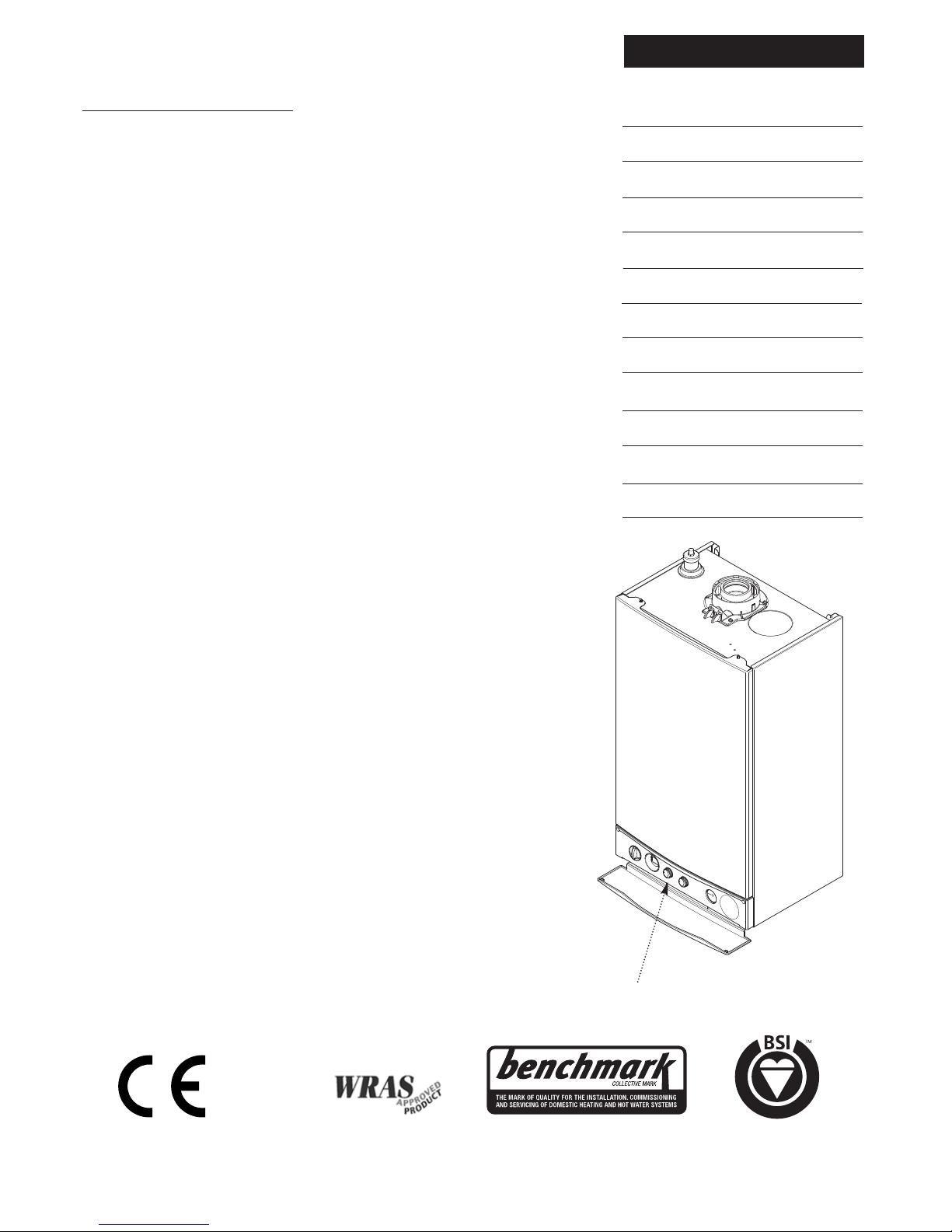
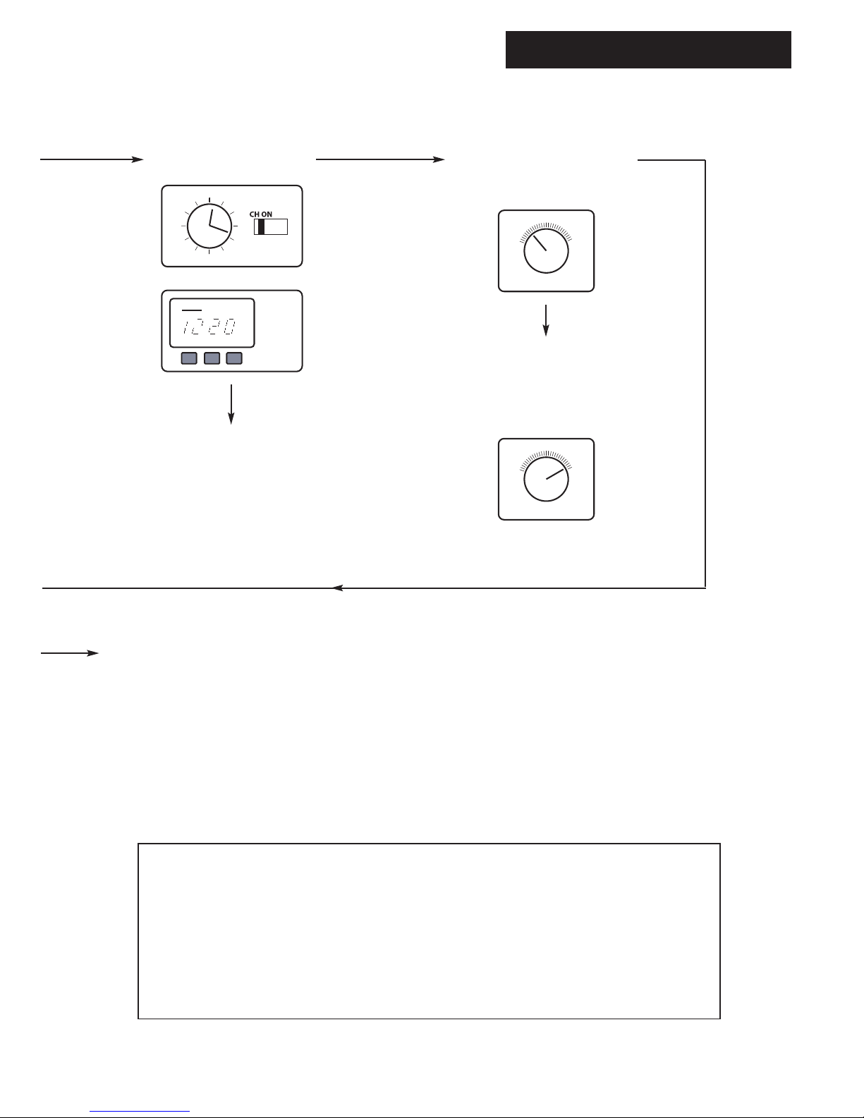
Boiler Controls - see opposite page
for Operating Quick Reference Guide
The Benchmark Scheme
Baxi Heating UK Ltd is a licensed member of the Benchmark Scheme which aims
to improve the standards of installation and commissioning of domestic heating
and hot water systems in the UK and to encourage regular servicing to optimise
safety, efficiency and performance.
Benchmark is managed and promoted by the Heating and Hotwater Industry
Council. For more information visit www.centralheating.co.uk
0086
ISO 9001
FM 00866
1.0 Quick Reference Guide
3
© Baxi Heating UK Ltd 2015
Reset
bar
0
1
2
3
4
Reset
bar
0
1
2
3
4
ON/OFF/Reset
Selector Switch
Display Central Heating
Temperature Control
Domestic Hot Water
Temperature Control
& Pre-heat Selector
System Pressure Gauge
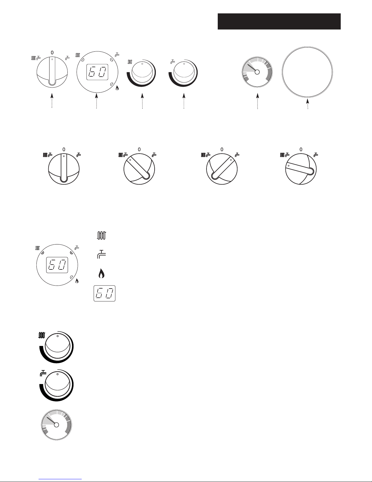
OFF Position
The boiler will not operate.
Central Heating Temperature Control
Turn the knob clockwise to increase or anticlockwise to decrease the temperature.
Range 25 - 80° C.
Domestic Hot Water Temperature Control & Pre-heat Selector
Turn the knob clockwise to increase or anticlockwise to decrease the temperature.
Range 40 - 60° C. It also activates the ‘Intelligent Pre-heat’ feature - see Section 4.0.
Central Heating Indicator - The indicator will illuminate when the boiler is in the central
heating mode.
Domestic Hot Water Indicator - The indicator will illuminate when hot water is being
supplied to a tap or shower.
Burner On Indicator - The indicator will illuminate when the burner has fired and is heating
your central heating or domestic hot water.
Boiler Output Temperature - In either the central heating or domestic hot water position
the display will illuminate showing the current boiler temperature in degrees centigrade.
Central Heating System Pressure - The normal operating water pressure is shown when the
needle is in the GREEN section of the gauge, between 1 and 2.5 bar. If the pressure exceeds 3
bar (needle in the RED section) the safety pressure valve will operate and a fault is indicated.
Contact your Installer.
Reset
Reset
Central Heating & Hot Water
Both Heating & Hot Water will operate.
Reset
Hold for approx 5 seconds and release.
Display
Position of
Timer (when fitted)
Reset
Domestic Hot Water
Hot Water will operate.
2.0 Troubleshooting
4
© Baxi Heating UK Ltd 2015
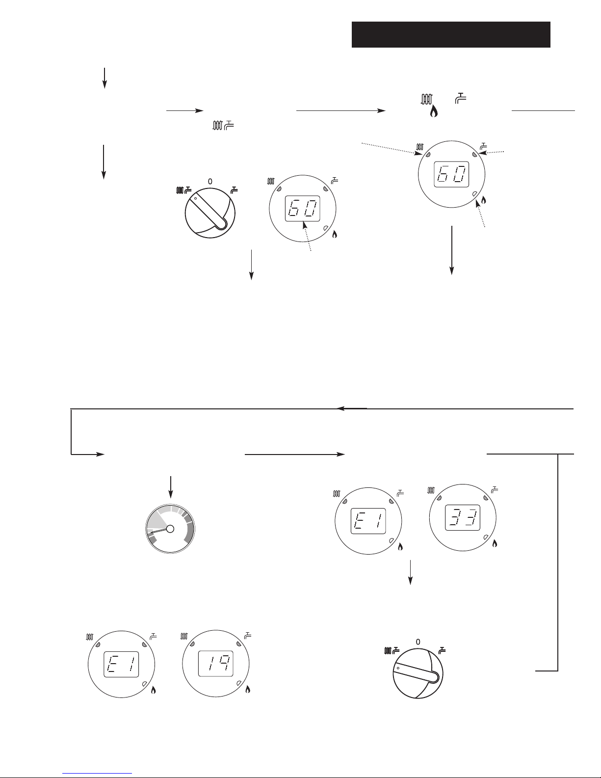
START
Make sure the gas supply is
turned ON and check if other
gas appliances are operating
(e.g. fire, cooker).
If no gas, consult your
supplier.
Is the ON/OFF/Reset
Select Switch in the
( ) position and
the display lit ?
Is the ( ) or ( ) light on
and the ( ) on ?
Check electricity to the
boiler is switched on.
Reset
Display
Central Heating
Indicator
Domestic Hot
Water Indicator
Burner On
Indicator
Boiler operating satisfactorily.
bar
0
1
2
3
4
Is the Central Heating System
Pressure needle in the GREEN
section, between 1 and 2.5 bar ?
If the reading falls below 1 bar
repressurise the system as
described in section 3.1.
Does the display show an error
code e.g. E133, E110 ?
Boiler not working
NO
NO
YES YES
YES
NO
Turn the ON/OFF/Reset
Selector Switch to Reset.
Reset
Error Code E119 showing low
pressure.
NO
YES
YES
NO
If boiler does not
Reset
2.0 Troubleshooting
5
© Baxi Heating UK Ltd 2015
Is the Timer ON and calling for
heat ?
Ensure timer is set for Central
Heating ON (see any
instructions supplied with
timer).
Is the Room Thermostat (if
fitted) set high enough ?
15
10
5
20
25
15
10
5
20
25
Turn Room Thermostat to
maximum setting (typical
example shown).
If you don’t know what you need to do to
get the boiler to light, or need help with
the system and controls, contact your
installer as soon as possible.
YES
NO
CONTACT YOUR
INSTALLER OR
SERVICE ENGINEER.
YES
12
1
2
3
4
5
6
7
8
9
10
11
CH ON
CH OFF
Typical
examples of
external timer
NO
3.0 Repressurising System
6
© Baxi Heating UK Ltd 2015
bar
0
1
2
3
4
bar
0
1
2
3
4
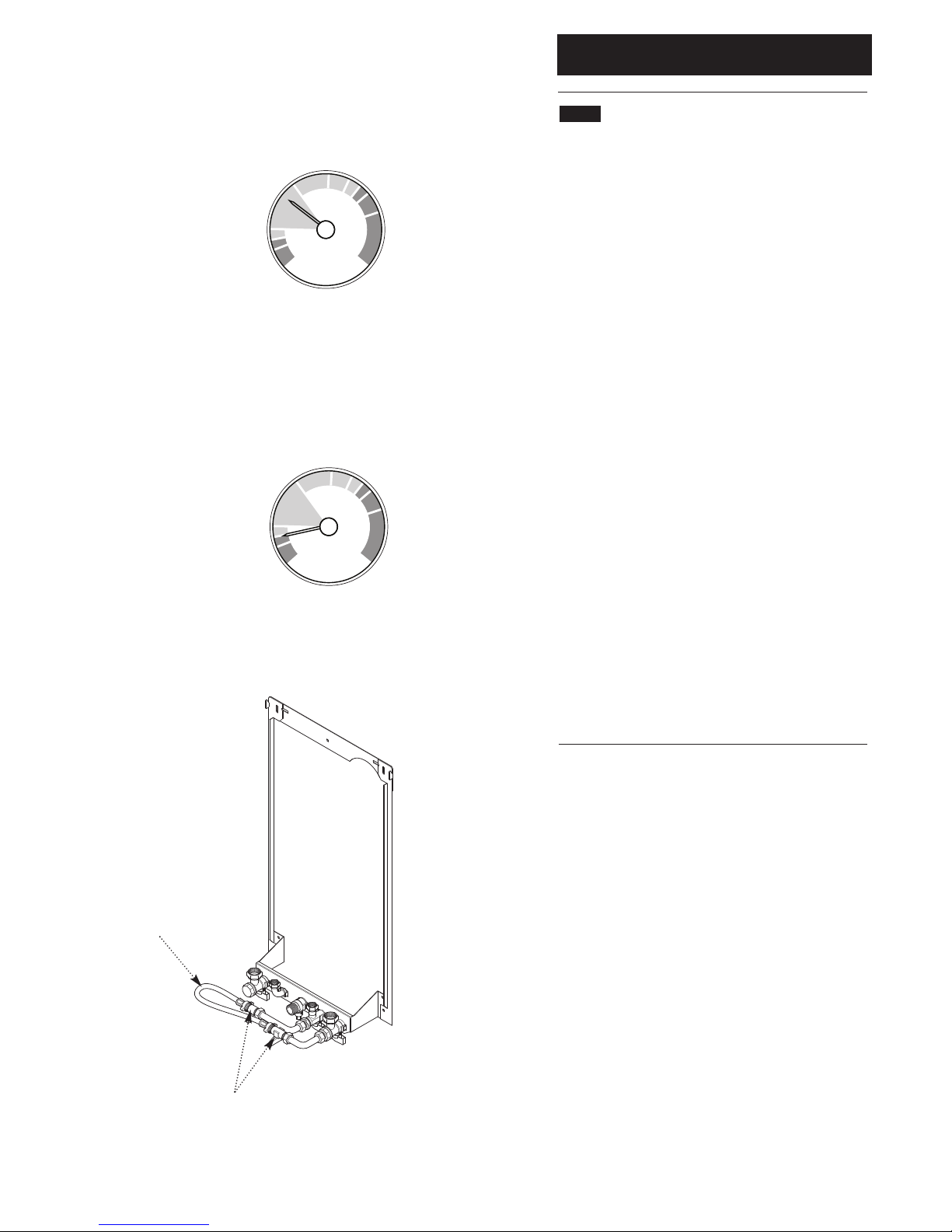
3.1 Central Heating System Pressure
1. The normal operating water pressure is when the
needle is in the GREEN section of the gauge, between 1
and 2.5 bar (Fig. 1). If the pressure exceeds 3 bar (needle
in the RED section) the safety pressure valve will operate
and a fault is indicated. Contact your installer.
2. It may be necessary to repressurise the system
occasionally (Fig. 2). The needle will be in the lower RED
section of the gauge, between 0 and 0.5.
3. A filling device (the filling loop) will be fitted on the
system. This will be on the boiler itself (Fig. 3), or on
pipework near to the boiler.
4. If you are unsure of its position, or cannot identify it,
consult the installer who fitted the boiler.
5. The filling loop consists of two taps and a separate
flexible pipe with connection fittings.
6. Only when repressurising should the flexible pipe be
connected between the two taps. Ensure that the nuts
on the pipe ends are tightened onto the taps.
7. Fully open one of the taps first, and then while
watching the pressure gauge, carefully open the second
tap.
8. When the needle on the gauge is indicating 1 or more,
in the green section of the gauge, turn both taps off.
9. Disconnect the flexible pipe from the taps (a small
amount of water may be present) and remove it. Keep
the pipe in a safe place for future use.
Fig. 1
Fig. 2
Normal Pressure
Requires
Repressurising
Flexible Hose
Taps
Fig. 3
 Loading...