

Page 1
Supplied By www.heating spares.co Tel. 0161 620 6677
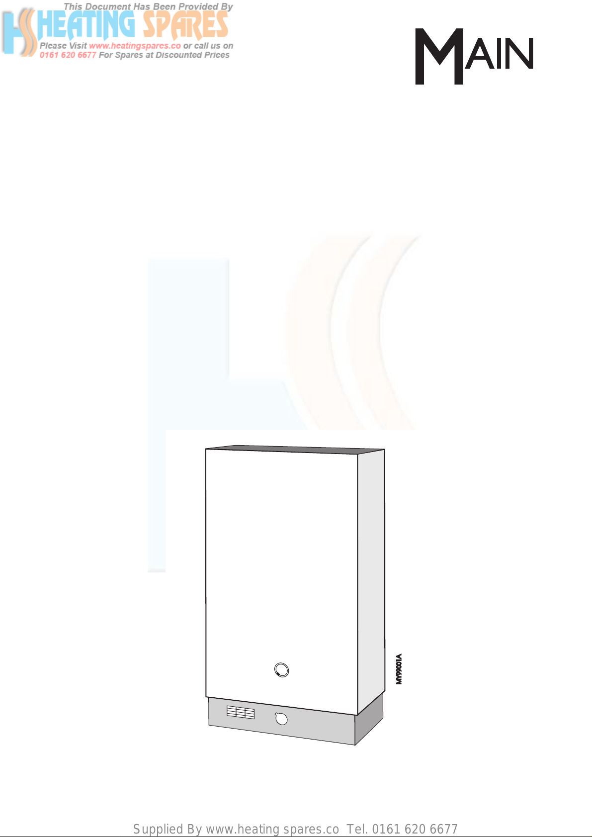
About the Heater See inside cover for models covered by these instructions.
This is a non spouted, gas fired, multipoint water heater.
For use with Natural Gas (G20) Only at 20 mbar and for use in GB/IE Only.
About Safety The Gas Safety (Installation and Use) Regulations.
‘‘ In your own interest, and that of safety, it is law that all gas appliances are installed by
competent persons, in accordance with the above regulations. Failure to install appliances
correctly could lead to prosecution.’’
Installation must be in accordance with the User, Installation & Servicing Instructions and the
rules in force.
Polythene bags used for packaging are a potential hazard to babies and young children and
MUST BE CAREFULLY DISPOSED OF IMMEDIATELY.
Leave these instructions with the user for use on future calls.
User, Installation & Service
Instructions
Multipoint
Water Heater
Page 2
Supplied By www.heating spares.co Tel. 0161 620 6677
2 Part No.5000893
Contents
Contents
User Instructions - For the User & Installer
User Information...................................................3
To Light the Pilot...................................................4
To Obtain Hot Water..............................................4
To Shut Down the PIlot.........................................4
To Alter the Settings.............................................5
Care of Y our Appliance.........................................6
Installation Instructions - For the Installer
1. Dimensions, Clearances &
Product Specificatin.............................................7
2. Installation Requirements....................................9
Codes of Practice...............................................9
Health & Safety Information...............................9
Energy Cut-Off Device.......................................9
Under Draining Board Installation......................9
Ventilation..........................................................9
Installation Conditions........................................9
Siting the Flue Terminal...................................10
3. Installation...........................................................11
3.1 Location.............................................11
3.2 Gas Connection.................................12
3.3 Water Connections.............................13
3.4 Lint Filter............................................13
4. Commissioning...................................................14
Servicing Instructions - For the Installer
5. Servicing.............................................................16
6. Replacement of Parts.........................................17
6.1 Piezo Unit...........................................18
6.2 General Access/Main Burner.............18
6.3 Thermocouple & Spar k Electrode......19
6.4 Pilot Injector.......................................19
6.5 Flame Safety Device..........................19
6.6 Pilot Viewing Glass & Seal.................20
6.7 Energy Cut-Off Device.......................20
6.8 To Drain the Appliance.......................21
6.9 Pressure Relief Valve.........................21
6.10 Water Governor..................................21
6.11 Automatic V alv e..................................23
6.12 Water Governor Venturi......................23
6.13 Thermostat Assembly - Thames.........24
6.14 Throttle Assembly - Thames...............24
6.15 Heating Unit - Thames........................25
6.16 Heating Unit - Mersey/Medway...........26
6.17 Descaling the Heating Unit.................26
7. Fault Finding.......................................................27
8. Short List of Spares............................................31
Washing Machine Information..................................33
Shower Information...................................................34
Models covered by these Instructions.
Mersey Super - G.C.No. 52 476 38
Medway Super - G.C. No.52 476 39
Thames - G.C. No. 52 476 40
Important - Installation, Commissioning, Service &
Repair
This appliance must be installed in accordance with the
manufacturer’s instructions and the regulations in
force. Read the instructions fully before installing or
using the appliance.
In GB this must be carried out by a competent person
as stated in the Gas Safety (Installation & Use)
Regulations.
Definition of competence: A person who works for a
CORGI registered company and holding current
certificates in the relevant ACS modules, or valid ACoP
equivalents, is deemed competent.
In IE this must be carried out by a competent person as
stated in I.S. 813. "Domestic Gas Installations".
Important – Failure to install and commission this
appliance to manufacturer’s instructions may invalidate
the warranty. This note does not affect your statutory
rights.
Warning - The addition of anything that may interfere
with the normal operation of the appliance without
express written permission from the manufacturer or
his agent could invalidate the appliance warr anty.In GB
this could also infringe the GAS SAFETY (Installation
and Use) REGULATIONS.
CORGI
All CORGI registered installers carry a CORGI
identification card and have a registration number. Both
should be recorded in your boiler Log Book.
You can check your installer is registered by
telephoning +44 (0) 1256 372300 or writing to:-
CORGI. 1 Elmwood, Chineham Business Park,
Crockford Lane, Basingstoke, RG24 8WG.
Page 3
Supplied By www.heating spares.co Tel. 0161 620 6677
3
Part No.5000893
Introduction & User Information
Introduction and User Information
• Samples of the Main multipoint water heaters have
been examined by Advantica Technologies Limited, a
United Kingdom Notified Body. The range is certified
to comply with the essential requirements of the Gas
Appliance Directive 90/396/EEC and are therefore
permitted to carry the CE Mar k.
• This appliance is not suitable for use with a swivel
spout.
• This appliance is room sealed instantaneous water
heater designed to supply hot water to several taps
which may be situated in different rooms, but not
necessarily at the same time.
• The pilot is lit by a piezo spark igniter; batteries or
electricity are not required.
• The main burners will automatically light when a
domestic hot water tap is turned on and go out when
the tap is turned off.
• Ensure that the clearances shown in (Page 7,
Installers section) are maintained at all times.
• Please take time to read through these
instructions to familiarise yourself with the water
heater.
• This appliance contains an energy cut-off device that
will shut down the gas supply to the appliance if the
water in the heat exchanger exceeds the anticipated
temperature limit.Although intended to guard against
an internal fault, it may be triggered inadvertently by
other causes, especially during the summer months
when the inlet water temperature is unusually high.
Allow the appliance to cool before re-lighting.
WARNING:
If the energy cut-off device is reacting to an
internal fault, the shut down ma y be accompanied
by noises from the heat exchanger and pipe work,
and it is possible that STEAM will come out of the
hot tap when turned on. If this occurs,arrange for
the appliance to be serviced.
Your installer/engineer will recommend
replacement of the Pressure Relief Valve
Assembly to ensure continued safety.
• Running Costs.To work out the approximate running
costs per hour for this fire, perform the following
calculation:-
Heat Input in kW x Cost Per kWh
= Running Cost Per Hour
Heat inputs for the various settings are shown in the
Technical Data & Costs per kWh are shown on your
gas bill.
• Washing Machines
Information regarding the use of washing machines
with this appliance is shown at the rear of these
instructions.
• Shower Systems
Information regarding the use of shower systems
with this appliance is shown at the rear of these
instructions. In hard water areas, shower roses may
require regular cleaning as scale my form and restrict
the flow of water.
The Mersey Super is Not suitable for use
with a shower system.
• WARNING:
The Outer Case of this Appliance MUST BE
CORRECTLY positioned and secured in
place before any attempt is made to light the
burners. If in doubt, call your Installer.
• IMPORTANT:
If it is known or suspected that a fault exists
on the appliance, it must not be used until
the fault has been corrected by a competent
person.
• REPLACEMENT PARTS:
WARNING:The use of replacement parts on
this appliance which are not recommended
by Potterton may affect the product safety,
performance and warranty.
We recommend that replacement parts be
obtained only from Curzon branches or
other recognised Potterton spares outlets.
Page 4
Supplied By www.heating spares.co Tel. 0161 620 6677
4 Part No.5000893
Read Through Before Lighting or Operating
Light the Pilot
Fig. 2
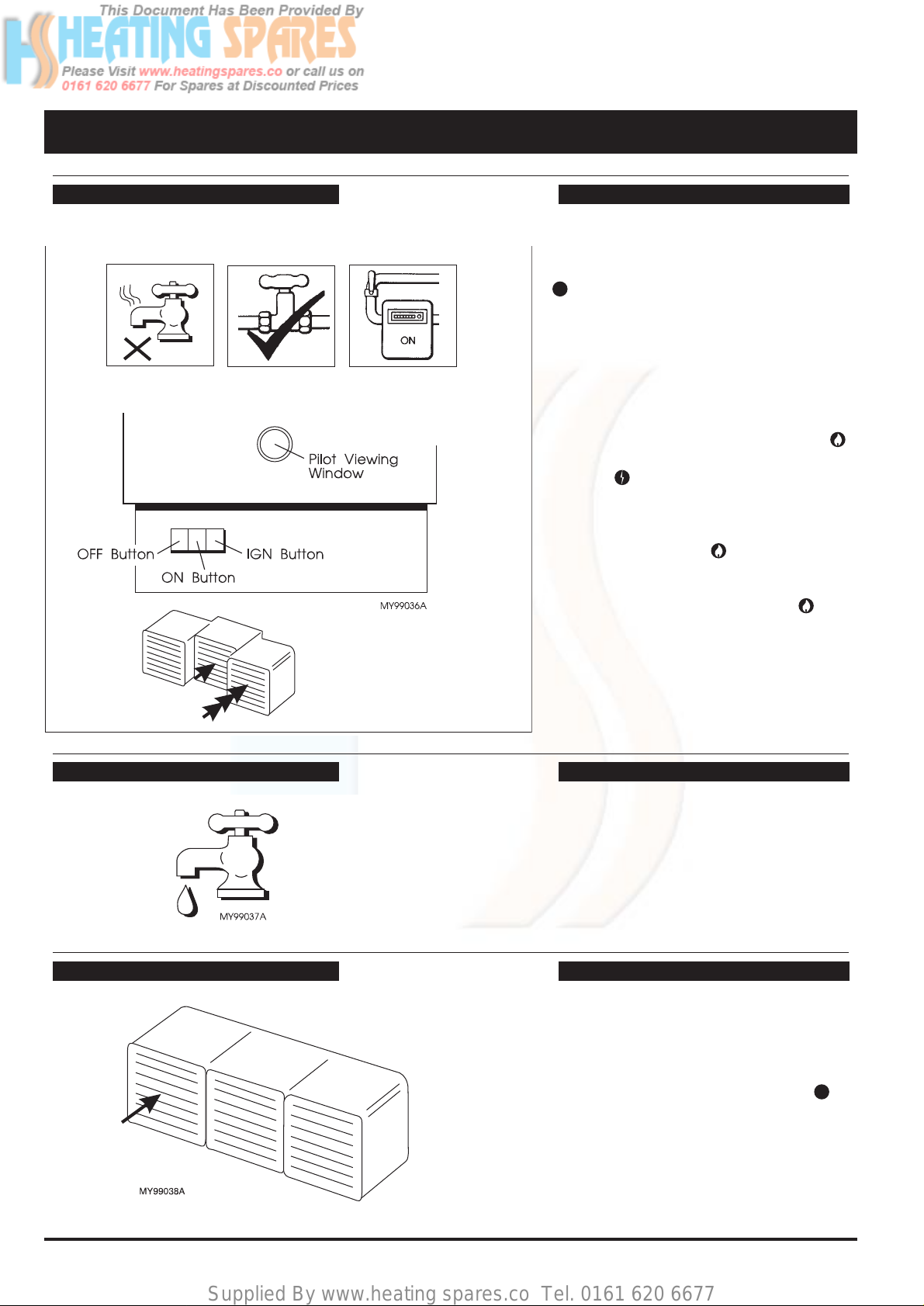
To Light The Pilot
Fig. 1
CAUTION: Should the pilot flame ever be
found to hav e gone out, press the OFF button
and wait at least 5 minutes for any
residual gas to dissipate before relighting the
pilot.
1.Ensure that the gas and water supplies are
turned ON, that all domestic hot water taps
are turned OFF.
2. Fully depress and hold the ON button
and repeatedly press and release the IGN
button until the pilot is lit.The pilot flame
can be observed through the pilot viewing
window.
3. Hold the ON button in for a further 10
seconds after the pilot is lit, then release.If
the pilot goes out, repeat the lighting
operation keeping the ON button
depressed a little longer.
• Once the pilot is lit and the appliance is in
the working position, hot water will be
obtained by turning on any of the hot taps.
Obtain Hot Water
• If the heater is in regular use the pilot may
be left alight.
• If the heater is not going to be used for
long periods press the OFF button .
The gas supply to both the pilot and main
burner will now be shut off.
• Check through the pilot viewing window
that the pilot flame is extinguished.
Shut Down the Pilot
Fig. 3
Page 5
Supplied By www.heating spares.co Tel. 0161 620 6677
5
Part No.5000893
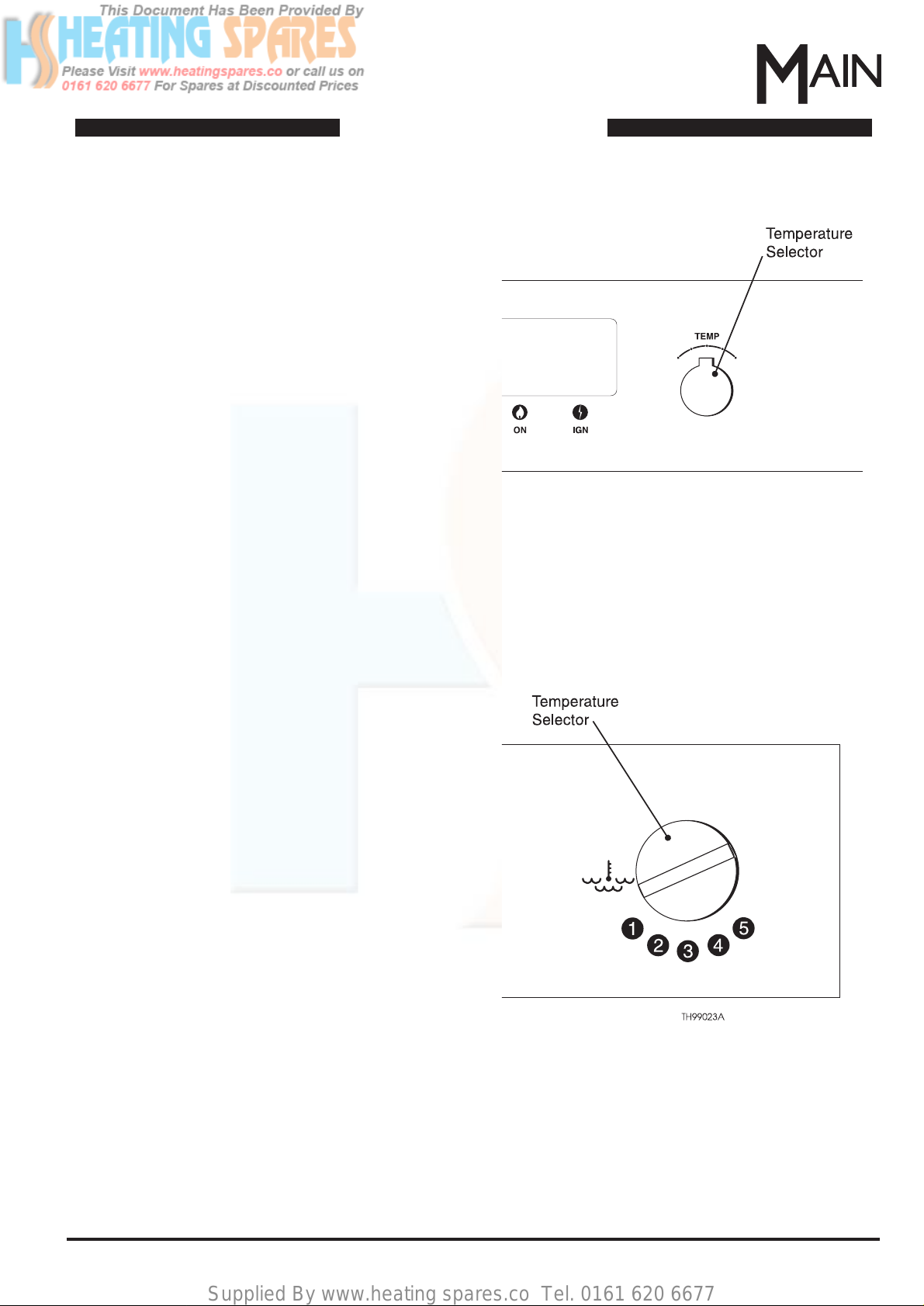
To Alter the Settings
Fig. 4
Fig. 5
To Alter The Settings
Medway Super
The temperature selector fitted to this appliance gives
access to a wide range of outlet temperatures.
Because the temperature of the water in the mains
supply varies with the seasons, the selector can be
used to compensate for this and the effect it has upon
the temperature of the water delivered to the hot taps.
In hard water areas, temperatures above 60 °C
encourage rapid scale formation and the selector
should be used to keep the water below this
temperature.
By turning the selector between '+' and '-', you can
draw water from the hot taps that ranges from very hot
to hand warm, howev er, when using a shower supplied
with water from this appliance, the selector should be
set in a high position and the shower mixer itself be
used to achieve a comfortable temperature.This
ensures that the control of the shower temperature is
at the point of use, and that the selector could not
accidentally be turned up, causing discomfort to the
shower user.
Thames
This appliance has a temperature selector with the
widest adjustment range of any Main Instantaneous
Water Heater. The actual temperature selected in the
lower part of the range will be subjected to the effect of
seasonal temperature variations in the mains supply.
This means that the lowest setting will give an
obviously lower temperature in winter than in the
summer.
The appliance has an integral thermostat which
automatically comes into operation to guard against
the selection of excessively high temperatures.There
are two benefits here, the first being safety, the second
is hard water scale. In hard water areas, temperatures
above 60 °C encourage rapid scale for mation and the
thermostat helps to avoid this.
By turning the selector between ' 5 ' and ' 1 ' , you can
draw water from the hot taps that ranges from very hot
to hand warm, however when using a shower supplied
with water from this appliance, the selector should be
set in a high position and the shower mixer itself be
used to achieve a comfortable temperature.This
ensures that the control of the shower temperature is
at the point of use, and that the selector could not
accidentally be turned up, causing discomfort to the
shower user.
Page 6

Supplied By www.heating spares.co Tel. 0161 620 6677
6 Part No.5000893
Care of your Appliance
This is the end of the User Instructions,
Page 7 onwards are for the Installers use only.
Care of Your Appliance
Servicing
As with all gas appliances, to ensure long life and saf e , troub le free operation, y our appliance m ust be inspected and
serviced at regular intervals by a competent person.
This should include a check to ensure continued clearance of combustion products and that there is no excessive
build up of scale on the heat exchanger in hard water areas.
The frequency of servicing will depend upon the particular installation conditions and usage but in general, once per
year should be adequate.
If service or spare parts are required, always quote the Appliance Identification Number and G.C.Number shown on
the Identification Badge.
The Identification Badge is brightly coloured and located underneath the controls tray at the front of the appliance
and will be visible after removal of the bottom cover.
Cleaning
The outer casing is stoved enamel and should be cleaned with warm, soapy water.DO NOT USE ABRASIVE
POWDERS SINCE THEY WILL SCRATCH THE ENAMEL SURFACE.
Frost Precaution
In frosty weather the pilot should be left alight. If the house is to be unoccupied for several days the heater should
be drained. Place a suitable receptacle below the appliance.
IMPORTANT
Check that the water service cock is fitted
correctly. The arrow on the service cock must
point towards the appliance.
If it points the other way DO NOT attempt to
drain the appliance and contact your Installer.
1. Turn OFF the gas at the gas service cock - A.
2. Turn OFF the water at the water service cock
- B.
3. Turn ON a domestic hot water tap to release
the pressure - C.
4. Remove the drain screw in the water service
cock , drain the appliance and refit the drain
screw - D.
5. Turn OFF the domestic hot water tap - E.
Fig. 6
Page 7
Supplied By www.heating spares.co Tel. 0161 620 6677
7
Part No.5000893
1. Dimensions, Clearances & Product Specification
Dimensions, Clearances & Product Specification
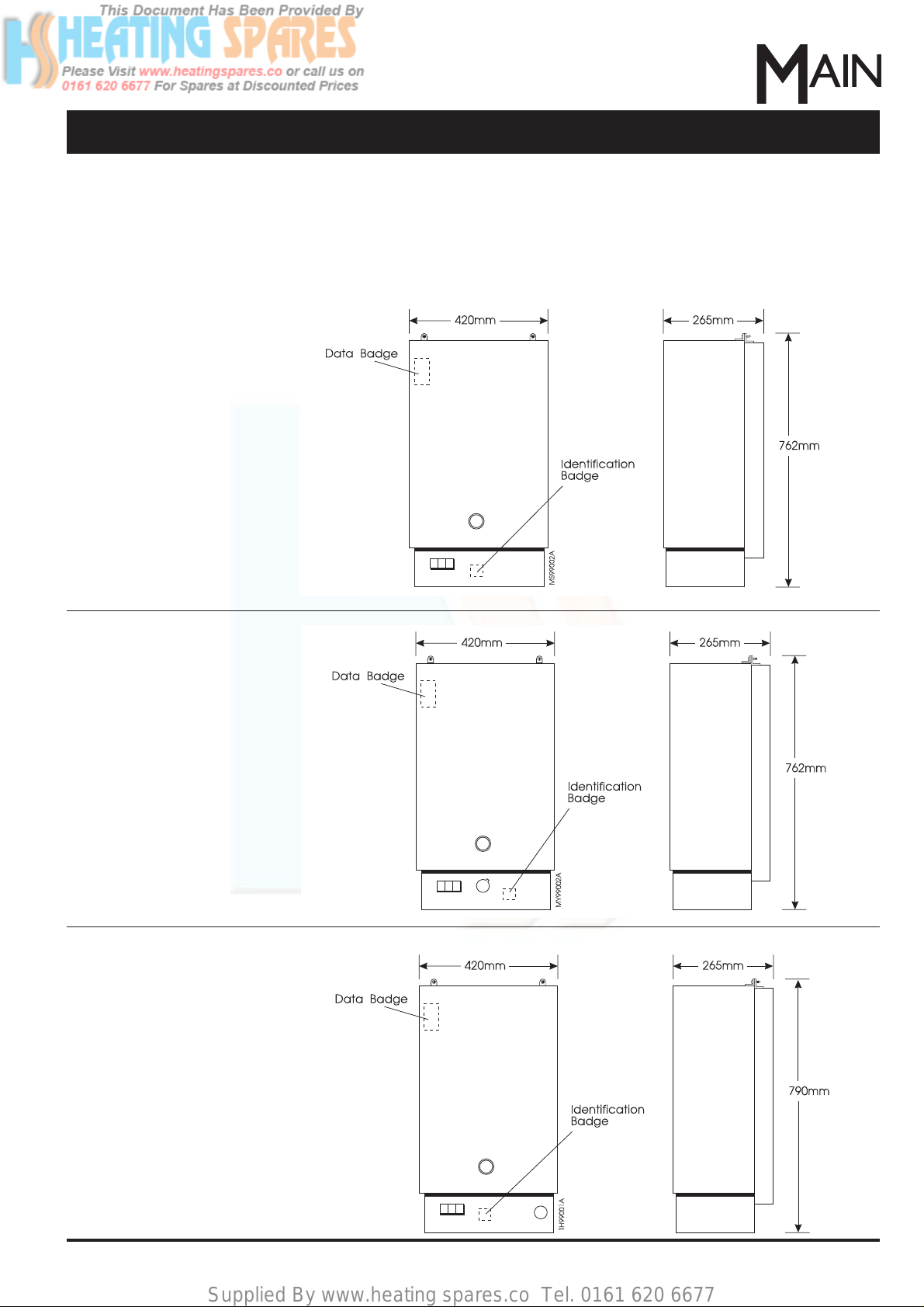
Minimum Clearances
For ease of servicing, allow as much clearance as possible below the appliance.
If the appliance is to be installed in a cupboard, DO NOT USE THE CUPBOARD FOR STORAGE.
Mersey Super
Medway Super
Thames
Fig. 7
Note: All models - the data
badge will be visible after
removing the outer case.The
identification badge will be
visible after removing the
bottom cover.
Clearance for All Appliances:
Above: 60mm (from case)
Below: 75mm
Sides: 5mm (each)
Front: A clearance of 220mm is
required in front of the appliance
for access during servicing. The
front clearance can be reduced
to 10mm providing the
door/cover installed can be
removed to expose the entire
case front.
Page 8
Supplied By www.heating spares.co Tel. 0161 620 6677
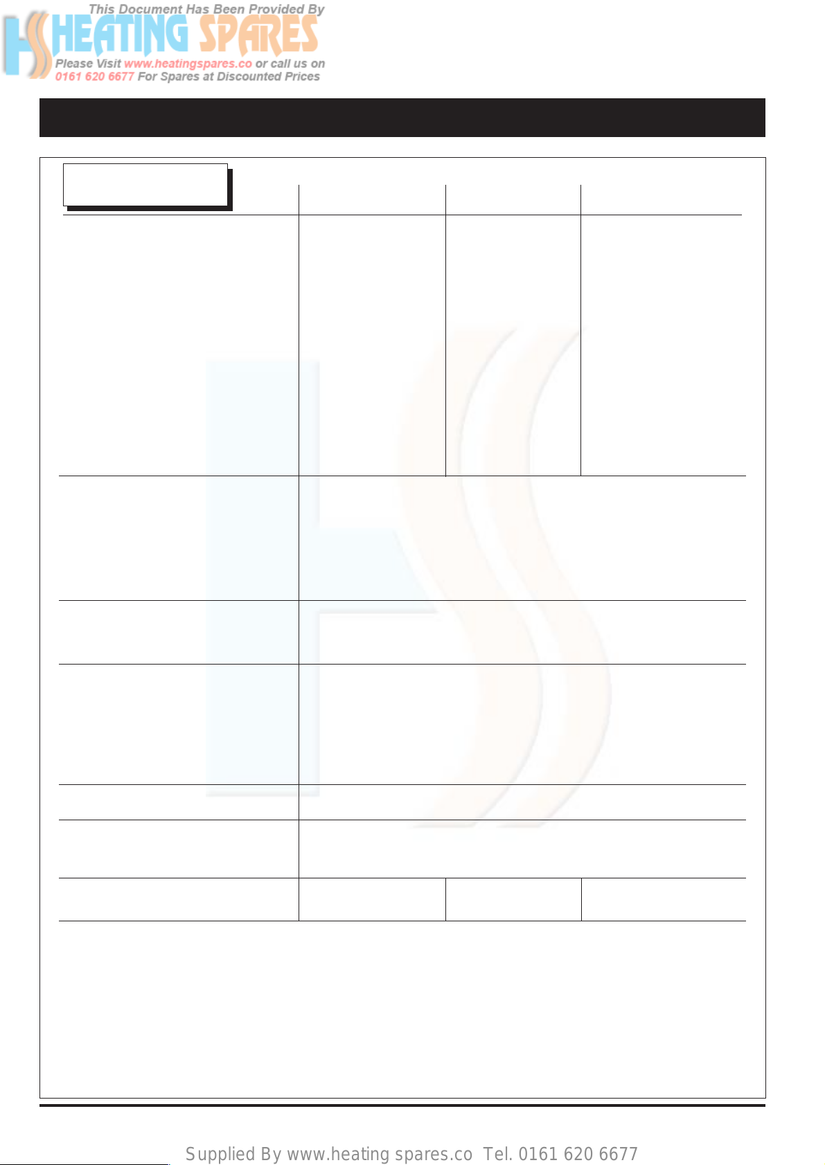
8 Part No.5000893Dimensions, Clearances & Product Specification
Models
Mersey Super Medway Super Thames
Output kW 22.7 23.3 23.3
Input kW 30.3 30.3 30.3
Gas rate m∆/h 2.91 2.91 2.91
Burner Pressure** mbar 12.5 12.5 12.5
Burner Injector Size mm 1.2 1.2 1.2
Pilot Injector Size mm 0.27 0.27 0.27
Appliance Weight
Installed with Water kg 18.6 18.6 18.5
Water Capacity litre 0.75 0.75 0.75
Flow Rate l/min 6.5 (at 50 °C rise)
Maximum Pressure Head bar 13
Minimum Pressure
Head Requirement at
Water Heater bar 1 (Under Flow Conditions)
Connections - Gas mm 15 (Copper Tail)
- Water mm 15 (Compression)
Telescopic Flue Kits mm (in) 100 - 150 (4 - 6) Sales Code 31/10321
150 - 230 (6 - 9) Sales Code 31/10322
230 - 380 (9 - 15) Sales Code 31/10323
380 - 610 (15 - 24) Sales Code 31/10324
SeDuct Flue Kit Sales Code 31/12968
Finish White stoved paint with contrasting chassis
Classifications CAT 1 2H
C11, C21,
CE Pin No. 87AP121 87AP125 87AP124
Notes:
* Additional external pipework and fittings may affect the resistance and must be taken into account on
installation.
** The nominal burner pressure should be 12.5 mbar and will only be obtained if the appliance inlet pressure
is correct at 20 mbar even when the appliance is running at full heat input.The meter should be capable of
passing 3 m∆/h of natural gas plus the requirements of any other gas appliances.See also Section 3.2, page
12.
Conversions:kW to Btu/h = kW x 3412.14, m∆/h to ft∆/h = m∆/h x 35.31, mbar to in wg = mbar x 0.4
Product Specification
Heat Input figures are
quoted as gross.
Page 9

Supplied By www.heating spares.co Tel. 0161 620 6677
9
Part No.5000893
2. Installation Requirements
• Codes of Practice
The appliance is suitable only for installation in GB and
IE and should be installed in accordance with the rules
in force.In GB, the installation must be carried out by
a CORGI Registered Installer.It must be carried out in
accordance with the relevant requirements of the:
• Gas Safety (Installation & Use) Regulations.
• The appropriate Building Regulations either The
Building Regulations, The Building Regulations
(Scotland), Building Regulations (Northern Ireland).
• The Water Fittings Regulations or Water byelaws in
Scotland.
Where no specific instructions are given, reference
should be made to the relevant British Standard Codes
of Practice.
In IE, the installation must be carried out by a Competent
Person and installed in accordance with the current
edition of I.S. 813 "Domestic Gas Installations" and the
current Building Regulations.
• Health and Safety Information
Under the Consumer Protection Act 1987 and Section
6 of the Health and Safety at Wor k Act 1974, we are
required to provide information on substances
hazardous to health. Small quantities of adhesives and
sealants used in the product are cured and present no
known hazards.The following substances are also
present.
Important: Later products are fitted with heat exchangers
that have a painted coating (in place of
lead/tin) and
present no known hazards.
Insulation and Seals
Material - Man Made Mineral Fibre.
Description - Boards, Ropes, Gaskets.
Known Hazards - Some people can suffer reddening and
itching of the skin.Fibre entry into the eye will cause foreign
body irritation which can cause severe irritation to people
wearing contact lenses. Irritation to respirator y tract.
Precautions - Dust goggles will protect eyes. People with a
history of skin complaints may be particularly susceptible to
irritation. High dust levels are only likely to arise following
harsh abrasion. In general, normal handling and use will
not present high risk, follow good hygiene practices, wash
hands before, touching eyes, consuming food, drinking or
using the toilet.
First Aid - Medical attention must be sought following eye
contact or prolonged reddening of the skin.
Heat Exchanger
Material - Copper with lead/tin coating.
Description - Finned copper tube.
Known Hazards - Inhalation or ingestion of lead dust or
fumes may cause headache and nausea.
Precautions - Unused heat exchangers present minimal
Installation Requirements
risk to health other than normal hygiene practices would
demand regarding washing before eating etc. Deposits
found on or below a heat exchanger that has been in use
could contain lead oxide. Avoid inhalation by using a
vacuum cleaner in conjunction with other cleaning tools
when servicing the boiler.
• Energy Cut-Off Device
This appliance contains an Energy Cut-Off Device that
will shut down the gas supply to the appliance if the water
in the heat exchanger exceeds the anticipated
temperature.
• Under Draining Board Installations
This appliance can be installed under a draining board,
a kit (Sales Code 22/18276) is available that contains
connection bends and a sheet showing recommended
pipework layouts.
• Ventilation
It is not necessary to have a purpose provided air vent in
the room or internal space in which the Water Heater is
installed. If the Water Heater is to be installed in a
cupboard or compartment, permanent air vents are not
required. Detail recommendations for air supply are given
in BS 5440:2.
• Installation
IMPORTANT: The area of wall covered by the appliance
must be flat.
The clearances required around the Flue Terminal are
shown on the Flue Template supplied with the Terminal
Pack.
The appliance must be fitted on an external wall to allow
the Flue Terminal to pass directly through the wall to the
outside air.
The Water Heater is suitable for installation against a
combustible wall e.g.wood cladding, provided the flue
duct is not closer than 25mm to combustible material. A
non-combustible sleeve should be installed to surround
the flue duct to provide a 25mm annular space.Further
guidence is given in BS5440:1
If the water heater is to be fitted into a building of
timber frame construction then reference must be
made to the current edition of Institution of Gas Engineers
Publication IGE/UP/7/ (Gas Installation in Timber Framed
Housing).
If the appliance is to be installed into a ‘‘SEDUCT’’ the
minimum duct required is 228 mm (9 in.) deep, 349 mm
(15fi in.) wide.
This appliance may take the place of an existing
appliance and will mount onto the original flue terminal
of any of the following:AVON, BRISTOL, MEDINA,
MEDINA D/L, MEDWAY, MERSEY, SEVERN 3,
SEVERN 4, SEVERN 5 and TRENT.
Page 10
Supplied By www.heating spares.co Tel. 0161 620 6677
10 Part No.5000893Installation Requirements
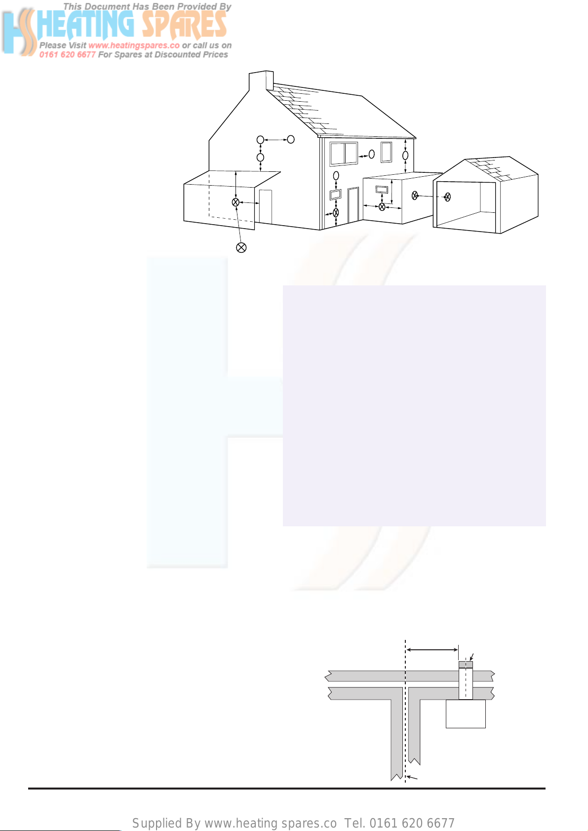
Fig. 8
• Siting the Flue Terminal
The following guidelines indicate the general
requirements for siting balanced flue terminals.
For GB recommendations are given in BS 5440 Pt.1.
For IE recommendations are given in the current
edition of I.S. 813 "Domestic Gas Installations".
The terminal must be positioned such that the
combustion products can disperse freely at all times.
In certain weather conditions a terminal may steam and
positions where this could cause a nuisance should be
avoided.
If a terminal is less than 2m above a balcony, above
ground, or above a flat roof to which people have
access, then a suitable terminal guard must be fitted.A
terminal guard is available (Part No. 205792), this
should be fitted centrally about the terminal.
If the terminal discharges onto a pathway or
passageway, check that the combustion products will
not cause a nuisance and that the terminal will not
obstruct the passageway.
If the flue terminal is fitted within 1 metre of a plastic
gutter, within 500 mm of a painted eave or a painted
gutter, an aluminium shield of at least 1 metre long,
should be fitted to the underside of the gutter or painted
surface. An air space of 5 mm should be left between
shield and gutter.
IMPORTANT: It is absolutely ESSENTIAL, to ensure
that products of combustion discharging from the
terminal cannot re-enter the building, or any other
adjacent building, through ventilators, windows, doors,
natural air infiltration, or forced ventilation/air
conditioning. If products of combustion are found to be
re-entering any building, the appliance MUST be
turned OFF IMMEDIATELY.
The distance from a natural draught appliance terminal installed parallel to
a boundary may not be less than 600 mm in accordance with the diagram
below.
Terminal
Assembly
Property Boundary Line
Natural Draught
600 min.
T op View
FLU0006A
N
I
I
G
L
F
M
I
A
A
F
H
J,K
D,E
H
Likely flue positions requiring
a flue terminal guard
B
C
FLU0001A
Natural Draught Balanced Flue
AaDirectly below an opening, air brick,
opening windows, etc.
B
a
Above an opening, air brick, opening window, etc.
C
a
Horizontally to an opening, air brick,
opening window, etc.
D Below gutters, soil pipes or drain pipes.
E Below eaves.
F Below balconies or car por t roof.
G From a vertical drain pipe or soil pipe.
H From an internal or external corner.
I Above ground, roof or balcony level.
J From a surface facing a terminal.
K From a terminal facing the terminal.
L From an opening in a carport (e.g. door, window)
into the dwelling.
M Vertically from a terminal on the same wall.
N Horizontally from a terminal on the same wall.
Terminal Position with Minimum Distance (mm)
For IE, refer to I.S. 813 "Domestic Gas Installation".
1500
300
600
300
300
600
300
600
300
600
600
1200
1500
300
a
In addition, the terminal should not be nearer than 300 mm to an opening
in the building fabric formed for the purpose of accommodating a built-in
element such as a window frame.See BS 5440 Pt. 1.
Page 11
Supplied By www.heating spares.co Tel. 0161 620 6677
11
Part No.5000893
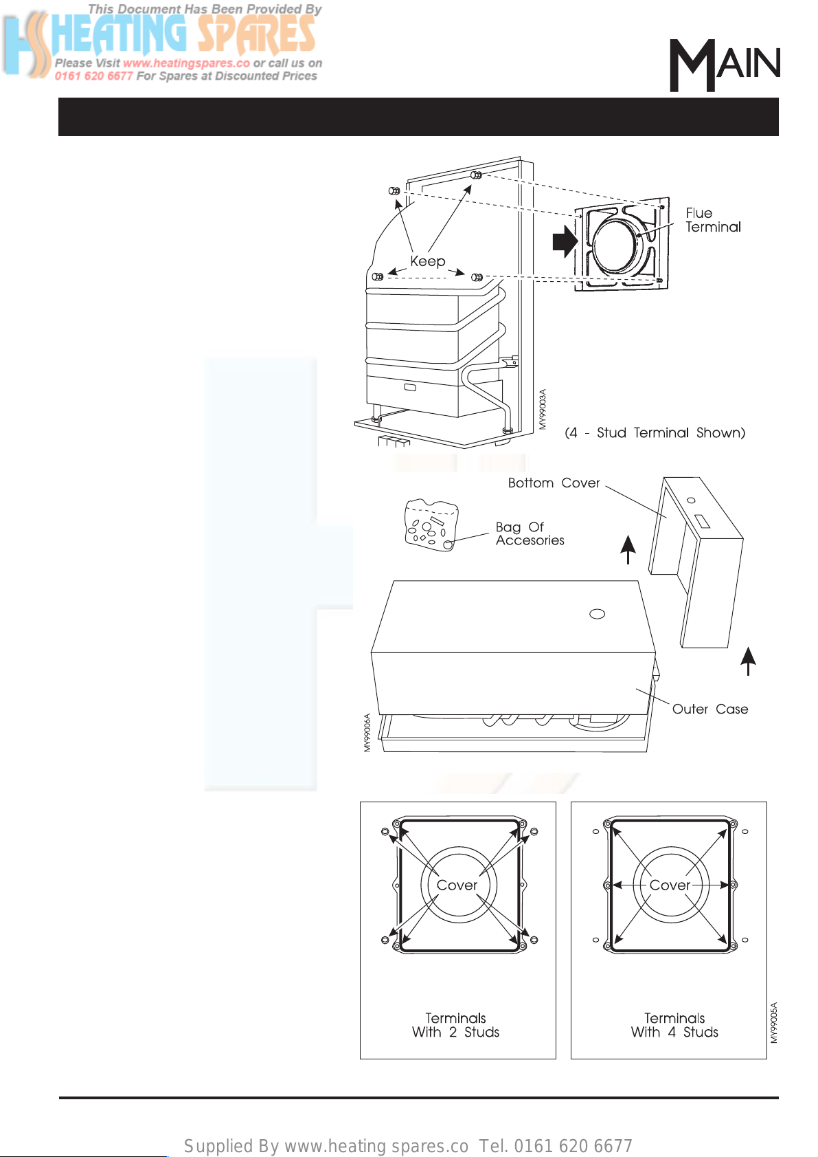
Installation
Fig. 11
3. Installation
3.1 Location
1. If the appliance is to be fixed to a suitable
existing terminal first isolate and remove
the old appliance.Leave the flue terminal
in place. Retain the fixing nuts and
washers. Make good any damage to the
brickwork or plaster around the terminal.
Cut off the existing pipework at a
convenient point below the appliance.
Important: Refer to the template
supplied with the flue for the positions of
the new water inlet, water outlet and gas
pipes.
2. If installing a new flue terminal, guidance
is given on the template sheet supplied
with the terminal pack.
Note: Where the appliance is to be
installed into a SEDUCT the minimum
duct required is 228mm (9in) deep,
349mm (15fi in) wide.
3. Where the building regulations require it,
a flue terminal guard should be fitted
symmetrically around the outer part of
the flue terminal.
4. Unpack the water heater. Find the bags
of accessories before discarding the
packaging.
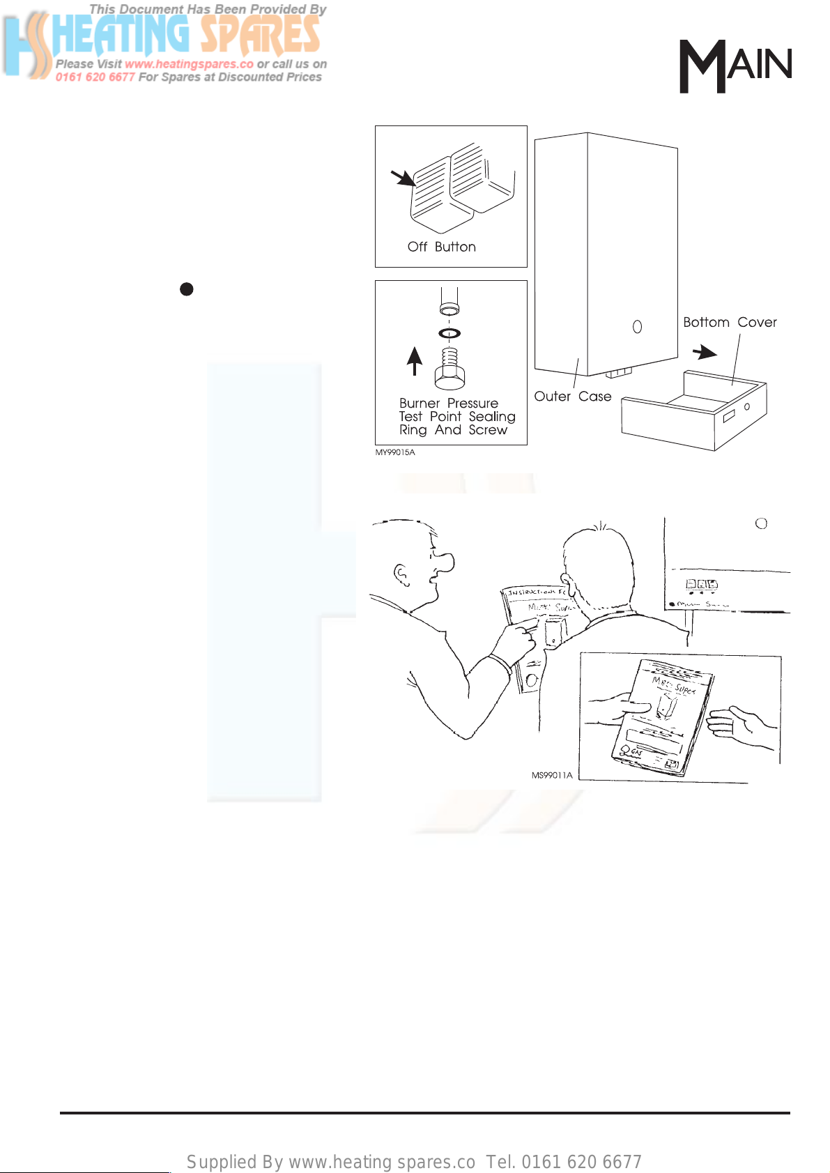
5. Slide off the bottom cover then remove
the three screws securing the outer case
and carefully lift it off.
6. Use the self adhesive discs supplied to
cover the unwanted fixing holes in the
back of the new appliance as shown.
Fig. 9
Fig. 10
Page 12
Supplied By www.heating spares.co Tel. 0161 620 6677
Securing Nuts &
12 Part No.5000893Installation
Fig. 13
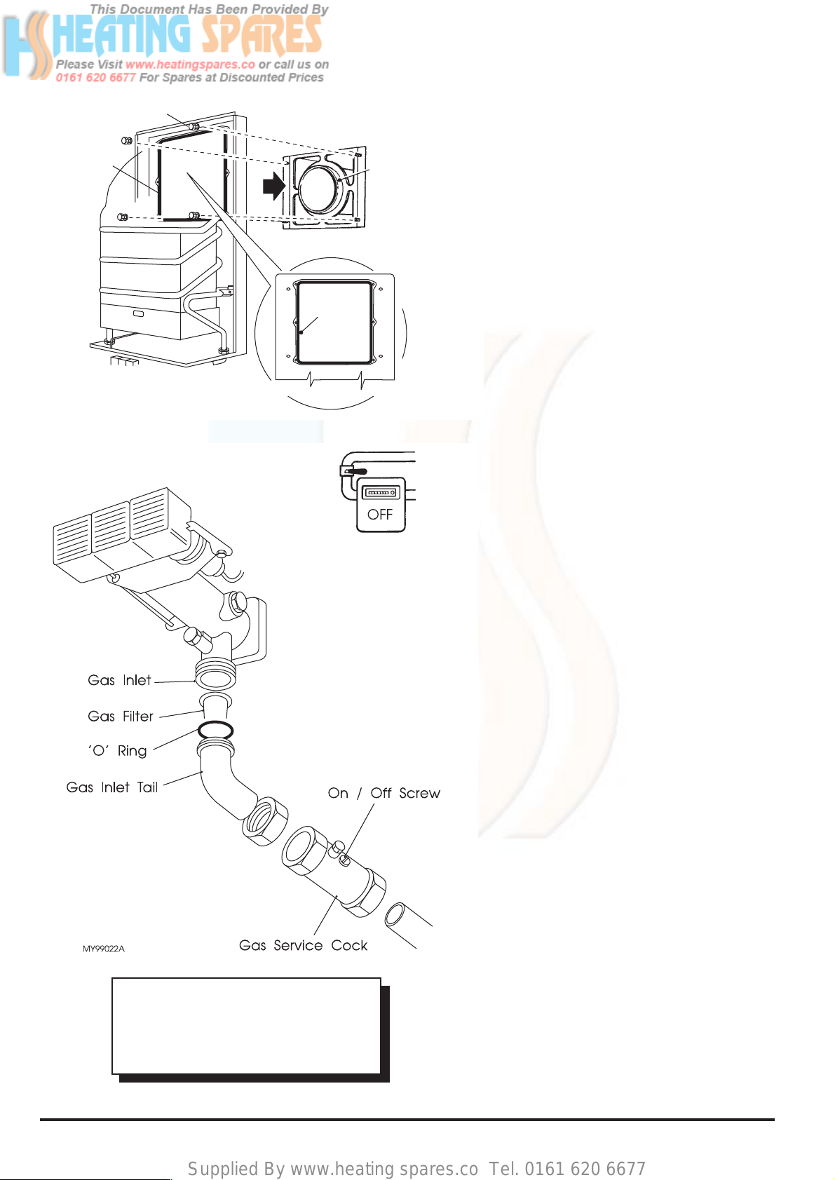
7. Fit the flue terminal sealing strip (packed
separately in the carton) into the recess
around the flue aperture in the back of
the appliance.
8. Lift the appliance into position, locating
the flue outlet into the circular duct on the
flue terminal.
9. Secure with the appropriate nuts and
washers.
3.2 Gas Connection
The meter and supply pipes must be capable
of delivering this quantity of gas in addition to
the demand from any other appliances in the
house and must be governed at the meter.
The pipe diameter required will depend on
the distance from the gas meter and the
number of bends used.
The gas installation should be in accordance
with the relevant standards. In GB this is BS
6891. In IE this is the current edition of I.S.
813 "Domestic Gas Installations".
1. Assemble the filter, ‘O’ ring and inlet tail
to the gas inlet.
2. Depending on whether the main supply
pipe is to be routed vertically or
horizontally to the appliance, connect the
gas service cock (stamped 'GAS') either
directly to the gas inlet tail or within the
supply pipe.
Note: The service cock should be as
close to the appliance as possible and
the ON/OFF screw in an accessible
position.
3. Ensure that the gas supply is isolated.
4. Connect to the gas supply.
5. Turn the gas supply on and purge
according to;in GB BS 6891 and in IE the
current edition of I.S.813 “Domestic Gas
Installations”.
IMPORTANT: DO NOT TRY TO LIGHT
THE APPLIANCE AT THIS STAGE. TO
ALLOW THE MAIN BURNER TO
IGNITE WITHOUT THE OUTER CASE
SECURED IN POSITION IS A HAZARD.
Fig. 12
Washers
Sealing
Strip
MY99004A
Sealing
Strip
Flue
Terminal
Rear View
Of Water
Heater
Page 13
Supplied By www.heating spares.co Tel. 0161 620 6677
13
Part No.5000893
Installation
Fig. 14
Fig. 15
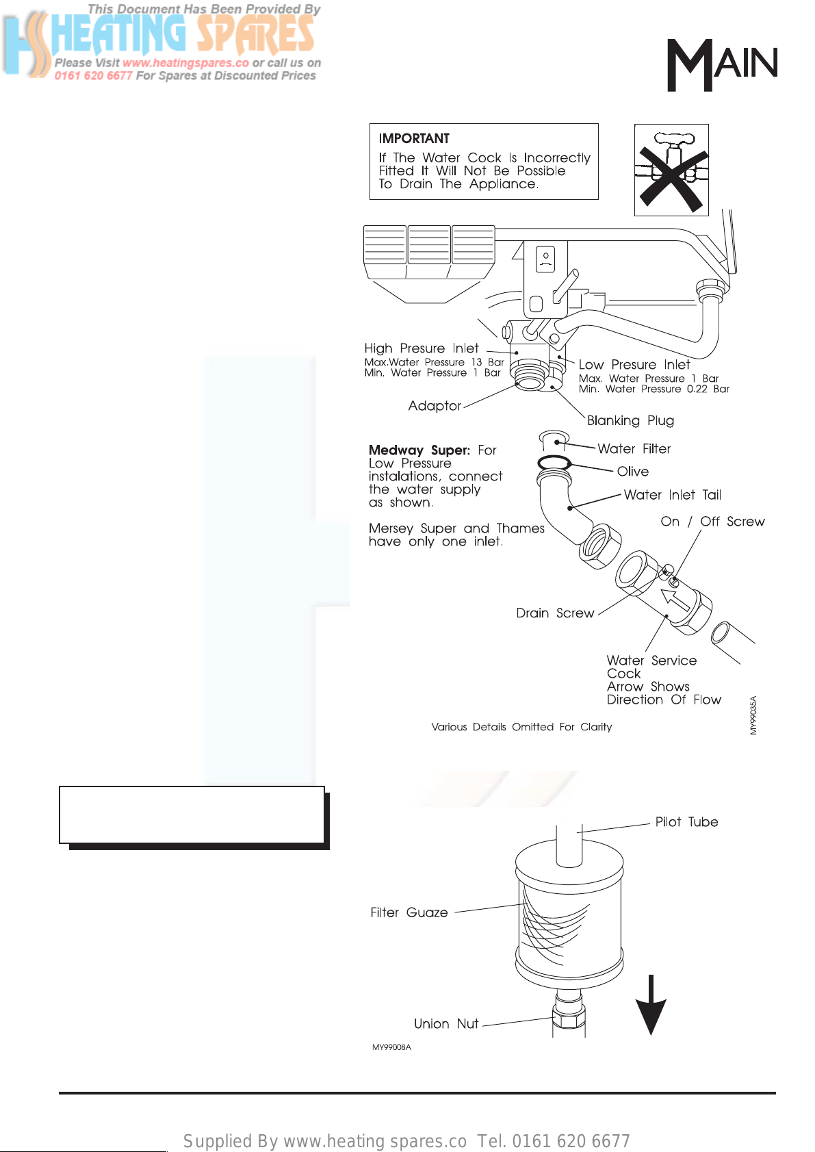
3.3 Water Connections
IMPORTANT: Flush out all foreign matter
from the supply pipe before connecting to the
service cock.
1. Assemble the filter, olive and inlet tail to
the water inlet. Note: The inlet tail need
not be used as a vertical supply can be
routed directly onto the water inlet.
2. Depending on whether the main supply
pipe is to be routed vertically or
horizontally to the appliance, connect the
water service cock either directly to the
water inlet tail or within the supply pipe.
Note: The service cock should be as
close to the appliance as possible and
the ON/OFF screw in an accessible
position.
3. Ensure that the mains water supply is
turned OFF.
IMPORTANT: When routing the supply pipe
to the appliance, ensure that it can be
lowered by approx. 25 mm to allow for
disconnection when servicing.
4. Connect the hot water supply pipes to the
water outlet - 15 mm compression.
5. Turn ON the mains water supply, turn ON
the water service cock and open all the
hot water outlets to allow water to flow.
Purge the air from the system by closing
the hot water outlets starting with the
lowest level and ending with the outlet at
the highest level.
6. Check for water leaks and remedy if
found.
IMPORTANT: DO NOT TRY TO
LIGHT THE APPLIANCE AT THIS
STAGE.
3.4 Lint Filter
This appliance has a lint filter fitted around
the base of the pilot tube.
Ensure that the filter gauze is located inside
both end caps and that the complete
assembly is correctly seated over the union
nut at the base of the pilot tube.
Page 14
Supplied By www.heating spares.co Tel. 0161 620 6677
14 Part No.5000893
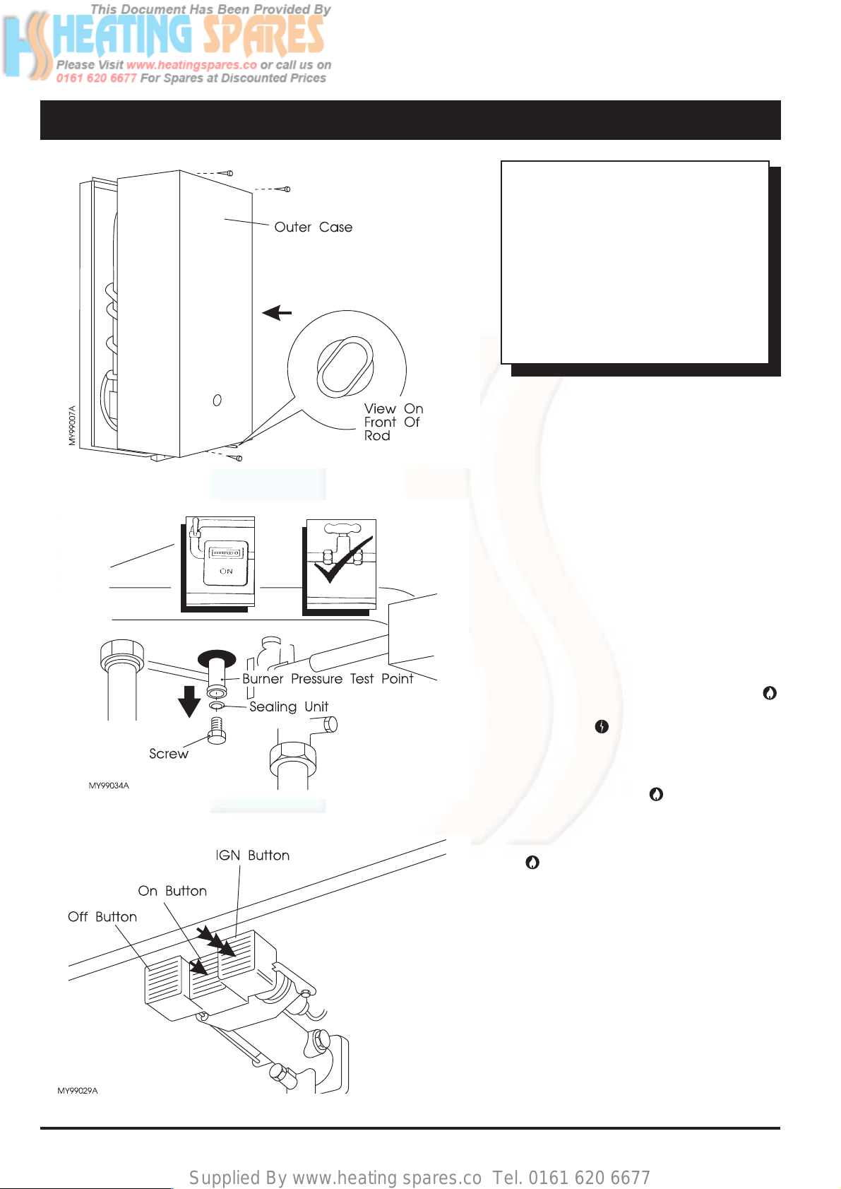
4. Commissioning
Complete the Installation
Fig. 16
WARNING:
The outer case of this appliance is not
merely a cosmetic device.It is a
functioning component in the air supply
to the burner and MUST BE replaced
with great care NOW, before any
attempt is made to light the burners.
TO ALLOW THE MAIN BURNER TO
IGNITE WITHOUT THE CASE IN
POSITION IS A HAZARD.
1. Refit the outer case ensuring it is
correctly seated then secure (3 screws).
Ensure that the temperature selector
control rod (if fitted) is set at its maximum
setting.
2. Ensure that the gas and water supplies
are turned ON.
3. Ensure that all hot water outlets are
closed.
4. Remove the screw and sealing ring from
the burner pressure test point and attach
a pressure gauge.
5. Fully depress and hold the ON button
and repeatedly press and release the
IGN button until the pilot is lit.The pilot
flame can be observed through the pilot
viewing window.
6. Hold the ON button in for a further
10 seconds after the pilot is lit, then
release. If the pilot goes out, repeat the
lighting operation keeping the ON button
depressed a little longer.
7. Test for gas soundness using a suitable
leak detection fluid on all external gas
joints.
8. Open a hot water outlet and the burner
will ignite.Allow the water to run for a few
minutes then check the burner pressure it should be 12.5 mbar (5 in w.g.), if the
pressure is not correct see the FAULT
FINDING section.
Fig. 17
Fig. 18
Page 15
Supplied By www.heating spares.co Tel. 0161 620 6677
15
Part No.5000893
Commissioning
Fig. 20
Note: Check the gas rate check, the gas
consumption after 3 minutes running should
be approximately 2.91 m
3
/hr (102.8 ft3/hr).
9. Turn the temperature selector spindle (if
fitted) from right to left , there will be a
noticeable change in the outlet
temperature.Turn the rod back to the
right (maximum).
10. Turn OFF the hot water outlet and press
the OFF button on the appliance.
Remove the pressure gauge and replace
the screw and sealing ring.
11. Relight the pilot. Tur n ON a hot water
outlet and check for gas soundness at
the pressure test point.
12. Turn OFF the hot water outlet.Slide the
bottom cover onto the appliance. Ensure
that the temperature selector spindle is
aligned with the selector knob, push the
bottom cover and with slight adjustment
the selector will positively locate on the
spindle.
• Explain to the user how to operate the
appliance.
• Show the user the position of the
Identification Badge.
• Advise the User that to ensure long life
and safe, trouble free operation, the
appliance must be inspected and
serviced at regular intervals by a
competent person.
• Leave these Instructions with the User
future use.
Fig. 19
Page 16
Supplied By www.heating spares.co Tel. 0161 620 6677
16 Part No.5000893Servicing
5. Servicing
Note: In hard water areas, scale may build
up on the push rod, seals and on the
underside of the diaphragm housing. They
may require regular descaling and
regreasing.
Operate the appliance noting any faults in the
component units.
Carry out the servicing procedure then
correct any other faults by reference to
'Replacement of Parts', in which section you
will find details of how to dismantle and
reassemble the following detailed
components.
Check that the burner ignition is smooth and
quiet when a hot tap is opened. The burner
ignition has been factory set and should not
need adjustment. However, if adjustment is
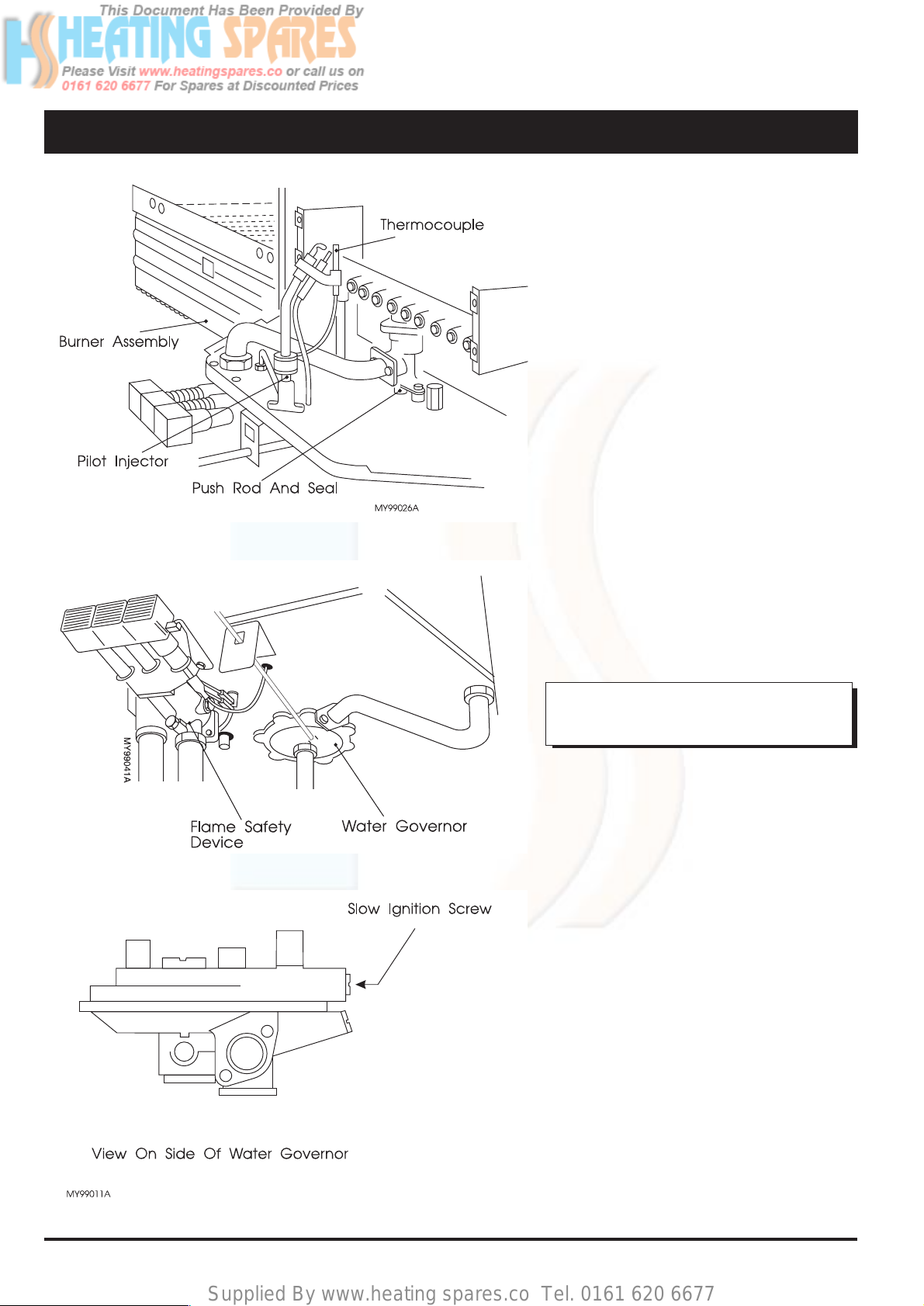
required a slow ignition screw is fitted to the
appliance and is situated above the cap
screw in the water governor body (Fig.23).
The screw is factory set 2 full turns out (anticlockwise) from the fully in position. Tur ning
the screw clockwise delays the ignition, anticlockwise advances the ignition.
WARNING:
NEVER OPERATE THIS APPLIANCE
WITH THE OUTER CASE REMOVED.
1. Check the piezo unit, flame safety device
and thermocouple, clean or replace if
necessary.
2. Remove the burner assembly and clean
using a soft brush or vacuum cleaner.
3. Check the pilot injector and clean or
replace if necessary. Also clean the lint
filter.
4. Remove the water gover nor assembly
complete with push rod. Replace the
seals if necessary. Descale and regrease
the push rod, washers and diaphragm
housing using Dow Corning 111 silicone
grease.
5. Check for water and gas soundness.
Replace 'O' rings, sealing washers and
gaskets where required.
6. Clean any deposits off the heating unit by
washing or brushing.Descale the heating
unit if required.
Fig. 21
Fig. 22
Fig. 23
Page 17
Supplied By www.heating spares.co Tel. 0161 620 6677
17
Part No.5000893
Replacement Of Parts
6. Replacement of Parts
1. When refilling, if water has been
drained from the system, turn on
all hot taps to purge air from the
system.Tur n them off in
sequence starting with the tap
at the lowest level.
2. When replacing parts, reassemble in reverse order
unless otherwise stated.
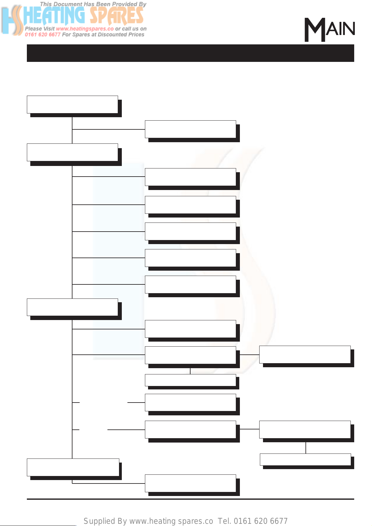
This chart shows the steps to be
taken in order access a specific part
or perform a particular function. Use
this chart in conjunction with the
detailed procedures on the following
pages.
Start
Descale Heating Unit - 6.17
Remove Piezo Unit - 6.1
General Access/Main Burner -
6.2
Thermocouple & Electrode - 6.3
Pilot Injector - 6.4
Flame Failure Device - 6.5
Pilot Viewing Glass
& Seal - 6.6
Energy Cut-Off Device - 6.7
Pressure Relief Valve - 6.9
Remove Heating Unit - 6.15/6.16
Water Governor Venturi - 6.12
Descale & Regrease
Water Governor &
Push Rod - 6.10
Automatic Valve & Burner
Manifold Complete - 6.11
Thermostat Assembly - 6.13
Throttle Assembly - 6.14
Descale & Regrease
Mersey/Medway
Thames
IMPORTANT:THE FOLLOWING WORK SHOULD ONLY BE CARRIED OUT BY A COMPETENT PERSON.
Drain the Appliance - 6.8
Page 18
Supplied By www.heating spares.co Tel. 0161 620 6677
18 Part No.5000893
6.1 Piezo Unit
It will NOT be necessary to remove the outer
case.
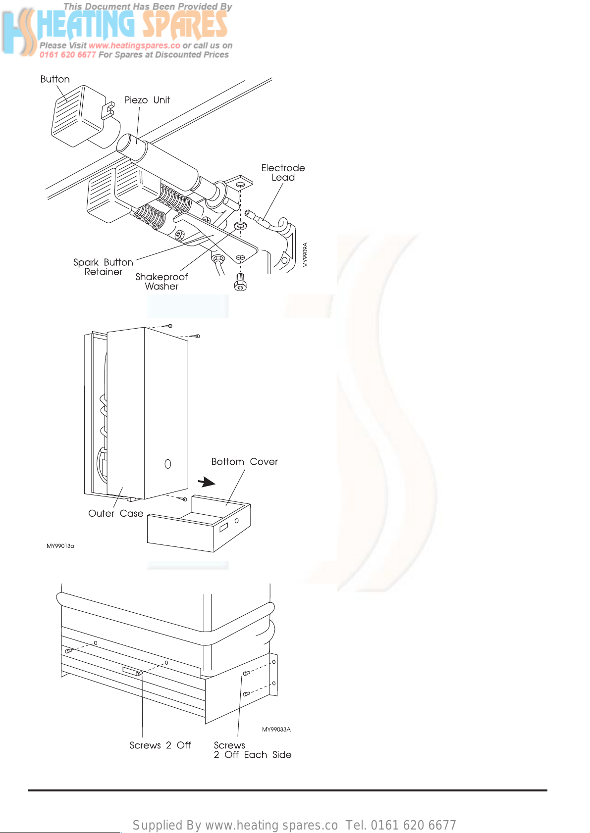
a. Slide out the bottom cover.
b. Disengage the electrode lead from the
piezo unit.
c. Remove or loosen and pull aside the
spark button retainer, taking care not to
lose the shakeproof washer.
d. Pull off the button and unscrew (anti-
clockwise) the piezo from its housing.
Note: When refitting the bottom cover,
ensure the temperature selector spindle (if
fitted) is aligned with the selector. Push the
bottom cover and with slight adjustment, the
selector will positively locate on the spindle.
6.2 General Access/Main Burner
a. Turn OFF the gas and water supplies at
the service cocks.
b. Slide out the bottom cover.
c. Remove the 3 fixing screws and pull off
the outer case.
d. Remove 4 fixing screws from the burner
assembly (2 each side).
e. Remove 2 screws securing the front to
the heating unit.
f. Pull the burner assembly slightly
forwards to clear the injectors, then pull
apart and withdraw taking care not to
snag the pilot assembly.
Note: If required, the burner assembly can
be dismantled and the burner bars replaced
individually. On re-assembly ensure that the
burner inlets locate in the 14 holes.
Note: On re-assembly of the burner
assembly take care not to snag the pilot
assembly. Ensure the front face of the
assembly has located on the two studs on
the heating unit. Re-fit the bottom cover as
outlined in Section 6.1.
Fig. 24
Fig. 25
Fig. 26
Replacement Of Parts
Page 19
Supplied By www.heating spares.co Tel. 0161 620 6677
19
Part No.5000893
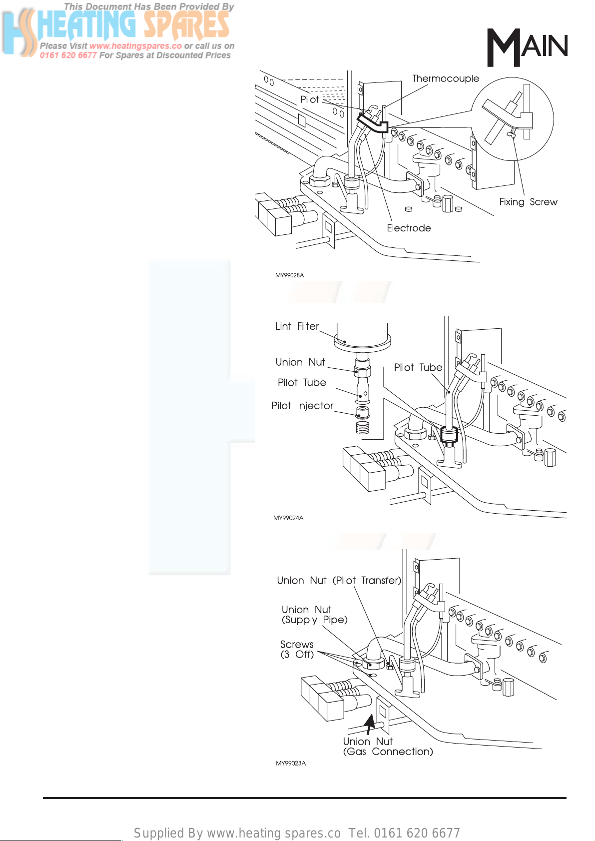
6.3 Thermocouple & Spark
Electrode
a. Gain general access - See 6.2.
b. Disconnect the nut securing the
thermocouple to the interrupter at the
chassis base.
c. Disconnect the electrode lead from the
back of the piezo unit, pull the lead up
through the grommet and remove.
d. Remove the fixing screw and bracket
then lower the spark electrode.
e. On re-assembly, ensure that the pilot
tube bends towards the rear of the
appliance. (The ther mocouple will be
vertical and nearest the burner manifold).
The thermocouple connection need only
be finger tight and a ⁄ turn.
6.4 Pilot Injector
a. Gain general access - See 6.2.
b. Lift up the lint filter, disconnect the union
nut and carefully lift up the pilot tube
taking care not to lose the pilot injector.
c. On re-assembly ensure the pilot injector
is correctly seated (taper side down) and
that the lint filter is correctly assembled
and located on the union nut.
Note: The lint filter can be cleaned if
required.
6.5 Flame Safety Device
a. Gain general access - See 6.2.
b. Disengage the electrode lead from the
piezo unit.
c. Release the ther mocouple from the back
of the flame safety device.
d. Release the union nuts above and below
the flame safety device.
e. Release the union nut securing the pilot
transfer tube to the flame safety device.
f. Remove the 3 screws securing the flame
safety device to the chassis base and
carefully withdraw the unit.
g. Re-assemble in reverse order.The
thermocouple connection need only be
finger tight and a ⁄ turn.
Fig. 27
Fig. 28
Fig. 29
Replacement Of Parts
Page 20
Supplied By www.heating spares.co Tel. 0161 620 6677
20 Part No.5000893
h. Test for gas soundness as follows:-
- Ensure the water service cock is in the
OFF position.This will ensure water
cannot flow and open the automatic
valve.
- Turn ON the gas, purge and light the
pilot, this will pressurise the burner
supply pipe.
- Test the gas supply to flame safety
device and burner supply pipe above the
flame safety device for gas soundness
using leak detection fluid.
j. Re-assemble remaining par ts and
ensure the water service cock is in the
ON position.
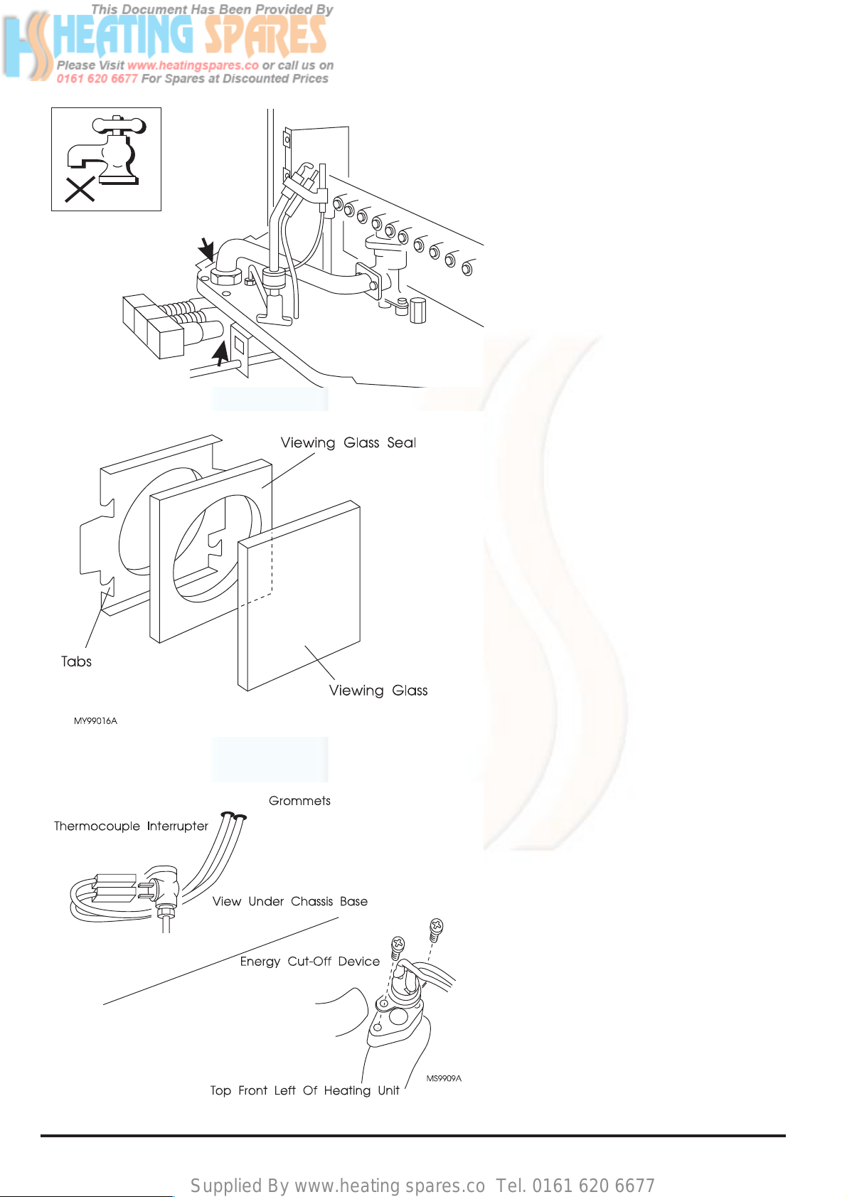
6.6 Pilot Viewing Glass & Seal
a. Complete steps a., b.and c. of Section
6.2.
b. The viewing glass and seal are fixed to
the inside of the outer case by 2 metal
tabs. Bend back the tabs and remove
the glass and seal. Secure the new
glass and seal to the outer case by
bending over the 2 spare straight tabs.
6.7 Energy Cut-Off Device
a. Gain general access - See 6.2.
b. Disconnect the energy cut-off leads
from the interrupter located on the
underside of the chassis.
c. Remove the 2 screws securing the
energy cut-off device to the heating unit
(located top front left).
d. Pull the leads complete with grommets
up through the chassis base.
e. Fit the new energy cut-off device which
comes complete with grommets.
Replacement Of Parts
Fig. 30
Fig. 31
Fig. 32
Page 21
Supplied By www.heating spares.co Tel. 0161 620 6677
21
Part No.5000893
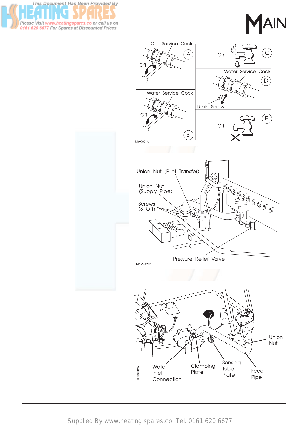
6.9 Pressure Relief Valve
a. Gain general access - See 6.2.
b. Drain the appliance - See 6.8.
c. Unscrew the valve and discard.
d. Screw in new valve.
6.8 To Drain the Appliance
a. Ensure that the gas service cock is
turned OFF.
b. Ensure that the water service cock is
turned OFF.
c. Open a hot water outlet.
d. Have a suitable container to hand .
Remove the drain screw from the water
service cock and allow the water to drain.
e. Close the hot water outlet.
6.10 Water Governor
a. Gain general access - See 6.2.
b. Drain the appliance - See 6.8.
c. Release the inlet water connection and
lower the pipework to clear the inlet.
d. Release the union nut and clamping plate
then remove the feed pipe. Replace the
'O' ring.
e. Remove the screw and plate securing the
sensing tube to the water governor.
Replace the 'O' ring.
Replacement Of Parts
Fig. 33
Fig. 34
Fig. 35
Page 22
Supplied By www.heating spares.co Tel. 0161 620 6677
22 Part No.5000893Replacement Of Parts
Fig. 38
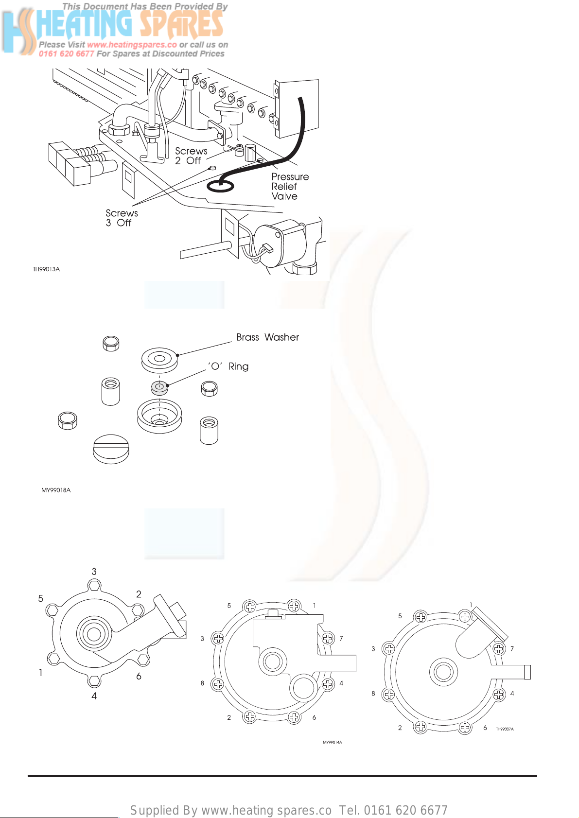
f. Remove 2 screws above the chassis
base securing the governor to the
automatic valve.
g. Remove 3 screws above the chassis
base securing the governor to the
chassis base.
h. Carefully withdraw the governor
complete with pressure relief valve, TAKE
CARE NOT TO BEND THE PUSH ROD.
IF THE ROD IS BENT, A NEW ONE
MUST BE FITTED.
j. Remove the push rod.
k. Remove 8 screws Medway/Thames, 6
screws Mersey and separate the two
halves of the water governor.
Descale & Regrease
l. Remove both the brass washer and 'O'
ring from the top opening. Clean the
washer.
m. Clean the top opening then pack with a
silicone grease such as Dow Corning
111. Fit a new 'O' ring and re-fit the brass
washer.
n. Hold the thrust plate, remove the fixing
nut and lift out the diaphragm assembly.
Clean or renew as required. On reassembly, tighten the fixing nut finger
tight plus a ⁄ turn only.
p. Check and if necessary replace the
transfer port 'O' ring.
q. Ensure the diaphragm assembly is
correctly seated then re-assemble the
two halves of the governor. Inser t the 8
screws and secure finger tight. Fully
tighten all 8 screws in the order shown.
r. Clean, regrease and re-fit the push rod or
replace with a new one.
Fig. 36
Fig. 37
Mersey Super
Medway Super
Thames
Page 23
Supplied By www.heating spares.co Tel. 0161 620 6677
23
Part No.5000893
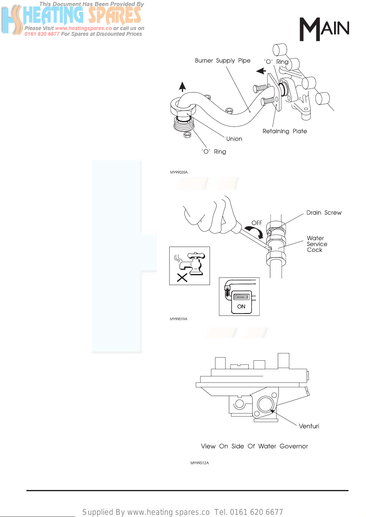
6.11 Automatic Valve and Burner
Manifold Complete
a. Gain general access - see 6.2.
b. Drain the appliance - see 6.8.
c. Remove the water governor - see 6.10.
d. Release the union above the flame safety
device.Do not lose the 'O' ring.
e. Release the retaining plate (2 screws)
and remove the burner supply pipe.Do
not lose the 'O' ring.
f. Prise the manifold location brackets apart
and carefully lift out the complete
assembly.
IMPORTANT: The automatic valve and
burner manifold are only available as a
combined assembly. Retain all screws and
'O' rings from the old assembly or renew.
Note: On re-assembly slide the pressure test
point extension tube through the grommet
before locating the manifold against the
location brackets.
g. Re-fit the water governor.
h. Re-connect the burner supply pipe.
j. Test for gas soundness as follows:-
- Ensure the water service cock is in the
OFF position, this will ensure that water
CANNOT flow and open the automatic
valve.
-Turn ON the gas, purge and light the
pilot, this will pressurise the burner supply
pipe.
-Test the burner supply pipe joints for gas
soundness using leak detection fluid.
k. Re-assemble remaining parts and ensure
the water service cock is in the ON
position.
IMPORTANT: If the automatic valve and
burner manifold complete is dismantled, it
can only be tested for gas soundness under
pressure AFTER blanking off all the
injectors.
6.12 Water Governor Venturi
a. Gain general access - See 6.2.
b. Drain the appliance - See 6.8.
c. Release the union nut and clamping plate
then remove the feed pipe.
d. Using a large flat bladed screwdriver that
will engage both slots, remove the
venturi.
e. Clean and re-fit.
Replacement Of Parts
Fig. 39
Fig. 40
Fig. 41
Page 24
Supplied By www.heating spares.co Tel. 0161 620 6677
24 Part No.5000893
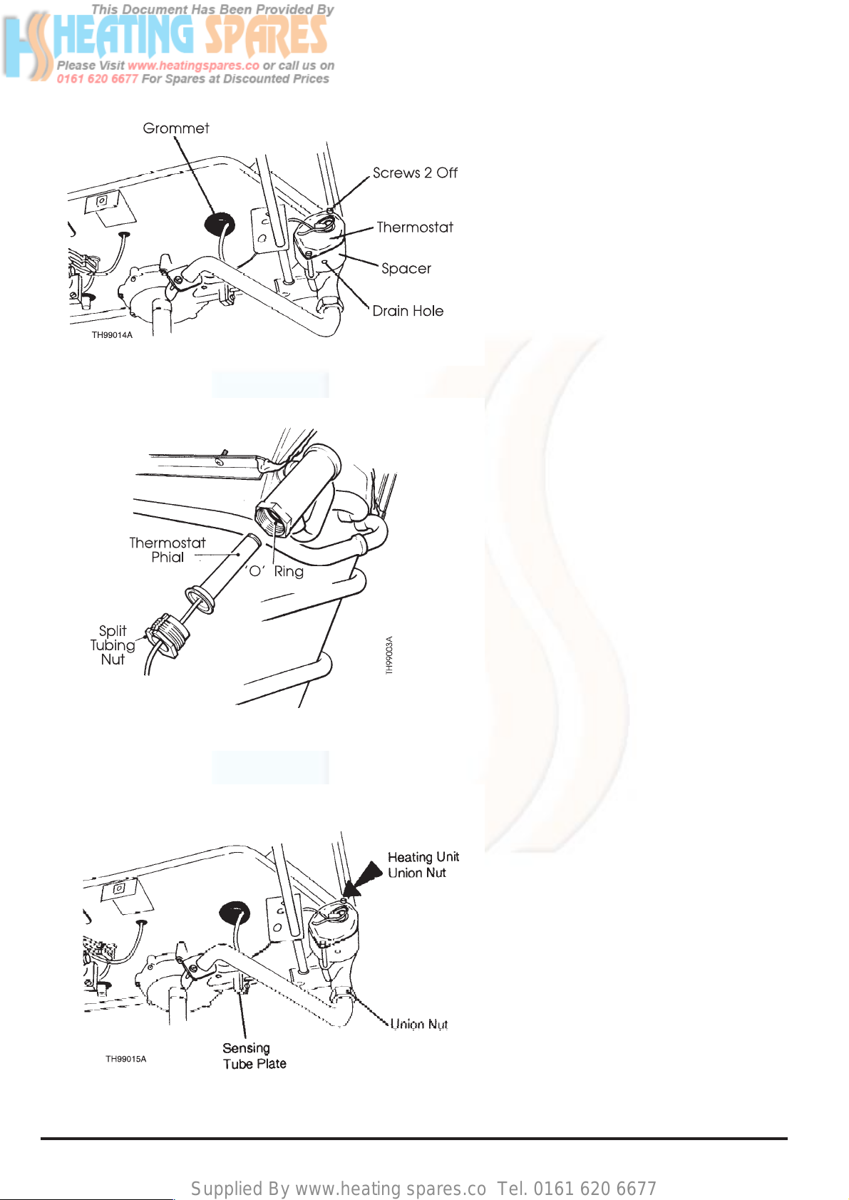
6.13 Thermostat Assembly Thames
a. Gain general access - see 6.2.
b. Drain the appliance - see 6.8.
c. Remove the thermostat phial from its
pocket.
CAUTION:To prevent possible damage to
the heating unit, release the split tubing
nut with a suitable spanner whilst
supporting the phial housing hexagon
boss with a second spanner.
d. Remove the 2 long screws to detach the
thermostat assembly and spacer from the
throttle body.
e. Remove the rubber grommet from around
the capillary tube in the chassis base then
pull the thermostat phial down through the
hole.
Re-Assemble as Follows:-
f. Feed the thermostat phial through the
hole in the chassis base. Re-fit the
thermostat assembly and spacer to the
throttle body, ensure that the spacer is
correctly located between the thermostat
flange and the retaining plate and that the
drain hole in the spacer is at the bottom
when relative to the whole appliance.
g. Ensure the 'O' r ing is correctly seated
within the thermostat phial housing,
carefully insert the phial taking care not to
disturb the 'O' ring. Re-fit the rubber
grommet around the capillary tube in the
chassis base.
6.14 Throttle Assembly - Thames
a. Gain general access - see 6.2.
b. Drain the appliance - see 6.8.
c. Remove the thermostat assembly - see
6.13.
d. Release the feed pipe union nut.
e. Release the screw and plate securing the
sensing tube to the water governor.
f. Release the union nut securing the
heating unit to the throttle at the chassis
base.
Note: When removing the throttle
assembly, the temperature selector
spindle will disconnect itself from the
throttle body. On re-assembly the rod
must be positioned before the throttle is
secured in place.
g. Remove the 2 screws securing the throttle
to the chassis base then remove the
throttle.
Replacement Of Parts
Fig. 42
Fig. 43
Fig. 44
Page 25
Supplied By www.heating spares.co Tel. 0161 620 6677
25
Part No.5000893
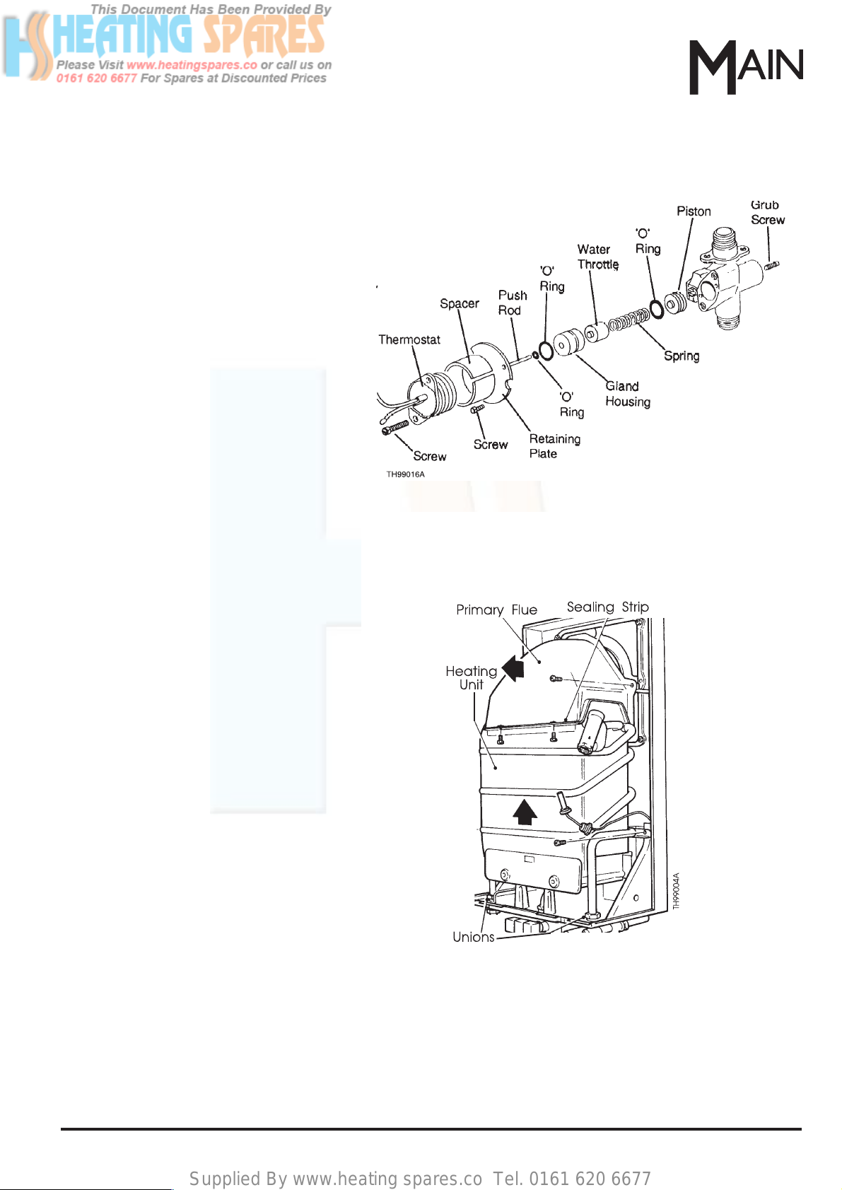
Descale/Regrease & Recalibrate
h. Remove the 2 screws securing the r
etaining plate to the throttle body.
i. Str ip down the throttle assembly, descale
and regrease using a silicone grease
such as Dow Corning 111. Replace 'O'
rings as necessary.
NOTE: Removal of the internal parts may
be difficult due to scaling etc, if
necessary, remove the grub screw from
the rear of the throttle body and screw in
one of the long thermostat screws.This
will force the internal parts out. KEEP
AWAY FROM FACE AND EYES.
j. On re-assembly, recalibrate the
thermostat as follows:Re-fit the grub screw.
Turn temperature selector to '5'.
Open a hot water outlet.
Adjust the grub screw until water
temperature is between 55° - 58° C.
WARNING:Keep the throttle body pointing a way from your face
and body when you turn the screw. The spring adjuster, spring
and gland housing will eject from the body with a lot of force.
TAKE GREAT CARE.
6.15 Heating Unit - Thames
a. Gain general access - see 6.2.
b. Drain the appliance - see 6.8.
c. Remove the 2 screws securing the energy
cut-off device to the heating unit (located
top front left).
d. Remove the thermostat phial from its
pocket - See 6.13.c.
e. Disconnect the 2 unions.
f. Remove 4 screws securing the unit to the
chassis.
g. Carefully pull the unit from the top and lift.
DO NOT lose the 'O' rings and washers.
h. Remove the primary flue, secured by 4
screws (2 front, 2 rear).
Note: On re-assembly, ensure that the 'O'
ring is carefully seated within the thermostat
phial housing and that the thermostat phial is
inserted carefully to avoid disturbing the 'O'
ring.
Replacement Of Parts
Fig. 45
Fig. 46
Page 26
Supplied By www.heating spares.co Tel. 0161 620 6677
26 Part No.5000893
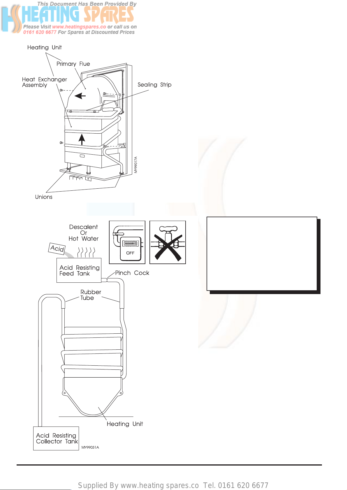
6.17 Descaling the Heating Unit
6.16 Heating Unit - Mersey/Medway
a. Gain general access - See 6.2.
b. Drain the appliance - See 6.8.
c. Remove the 2 screws securing the
energy cut-off device to the heating unit
(located top front left).
d. Disconnect the 2 unions.
e. Remove 4 screws securing the unit to the
chassis.
f. Carefully pull the unit from the top and lift.
DO NOT lose the 'O' rings and washers.
g. Remove the primary flue, secured by 4
screws (2 front, 2 rear).
a. Gain general access - See 6.2.
b. Drain the appliance - See 6.8.
c. Remove the heating unit - See 6.16.
Note: On the Thames model it will be
necessary to blank off the thermostat
phial housing with a suitable plug.
d. Invert the heating unit on a suitable
bench or table.
e. Using rubber tube and acid resisting
tanks, assemble as shown in Fig.48.
f. Fill the upper container with a proprietary
brand of descalent or a solution of 10
parts water to 1 part hydrochloric acid.
The water should preferably be hot, then
add ACID to WATER, not water to acid.
g. Adjust the pinch cock and allow the fluid
to slowly pass through the heating unit
into the collecting tank.
h. Continue the process until the fluid
ceases to bubble.It may be necessary to
replenise the solution.
i. Disconnect and thoroughly wash out the
heating unit with clean water.
WARNING: ACID/WATER SOLUTION
MUST BE USED WITH EXTREME
CAUTION.TAKE CARE NOT T O SPLASH
ONTO SKIN OR INTO THE EYES.WASH
ANY AFFECTED AREAS WITH LARGE
AMOUNTS OF COLD WATER AND
SEEK MEDICAL ADVICE. CARRY OUT
THE FOLLOWING OPERATION OUT OF
DOORS. ACID/WATER SOLUTION CAN
DAMAGE FURNISHINGS ETC.
Replacement Of Parts
Fig. 47
Fig. 48
Page 27
Supplied By www.heating spares.co Tel. 0161 620 6677
27
Part No.5000893
Fault Finding
SYMPTOM POSSIBLE CAUSE SOLUTION
1. Turn on the gas at the gas
service cock and/or the main
gas line.
2. Purge the air line by depressing
and holding the centre ON
button, this may take 2-3 mins.
3. Follow the lighting instructions
located on the bottom cover or
refer to these Instructions.
4. Re-connect the electrode lead.
5. The gap between the electrode
tip and the pilot hood should be
3-4mm.
6. Check the electrode lead is
routed clear of all metal parts.
7. Clear injector by blowing
through or replace with pilot
injector Part No. 19/12690. Also
clean the lint filter located at the
base of pilot tube.
8. Replace any faulty components
found. Piezo Unit - Part No.
10/11935. Electrode Assembly Part No.10/17493.
9. Call in your local gas supplier.
1. Gas not tur ned on.
2. Air in gas line.
3. Incorrect pilot lighting
procedure.
4. Electrode lead not connected
to the rear of the spark igniter.
5. Incorrect spar k gap.
6. Current tracking to ear th.
7. Pilot injector blocked.
8. Faulty components.
9. No gas to the appliance.
PILOT WILL NOT LIGHT
1. Tighten the connections.
2. Pilot injector partially blocked,
clear by blowing through or
replace. Check the gas inlet
pressure is correct - 20 mbar.
Also clean the lint filter located
at the base of the pilot tube.
3. Replace the ther mocouple Part No.10/17461.
4. Replace flame safety device Part No.10/13477.
5. Tighten connections.
6. Check for continuity and replace
if necessary - Part No.
10/17792.
PILOT LIGHTS BUT WILL NOT
REMAIN ALIGHT
1. Ther mocouple connections
loose.
2. Pilot flame 'soft' or too small to
heat the thermocouple tip.
3. Ther mocouple wor n out or
damaged.
4. Faulty magnet unit in the flame
safety device.
5. Energy cut-off device
connections loose.
6. Energy cut-off device may be
faulty.
5. Fault Finding
Page 28
Supplied By www.heating spares.co Tel. 0161 620 6677
28 Part No.5000893
SOLUTIONPOSSIBLE CAUSESYMPTOM
PILOT LIT BUT MAIN BURNER
WILL NOT LIGHT ON WATER
FLOW
1. Gas inlet pressure low.
2. Low water flow caused by
blocked water filter.
3. Faulty diaphragm.Will also
cause a high water rate.
4. Automatic gas valve push rod
jammed. May also cause a high
water rate.
5. Slow ignition screw incorrectly
set.Will also cause a high water
rate.
6. Ther mostat throttle stuck in the
open position. Will also cause a
high water rate.
1. Call in your local gas supplier
2. Clean the debr is from the filter.
3. Replace the Diaphragm
Assembly - Part No.10/17572.
4. Dismantle clean and regrease
using Dow Corning 111 silicone
grease. Handle the push rod
with care, do not bend.
5. See Fig.23 for the position of the
screw.Turning the screw
clockwise delays the ignition,
anti- clockwise advances the
ignition.The screw should be
set 2 full turns out (anticlockwise) from the fully in
position.When correct the
burner ignition should be
smooth and quiet when a hot
water outlet is opened.
6. Descale, regrease and replace
'O' rings as necessary.
NO OR LOW WATER FLOW RATE 1. Blocked water filter.
2. Heat exchanger blocked with
lime.
3. Loss of ser vice water main
pressure.
1. Clean the debr is from the filter.
2. Descale or replace - Part No.
10/17558.
3. Contact your Local Water
Authority.
HIGH WATER FLOW RATE
See
LOW WA TER TEMPERATURE
HIGH WATER TEMPERA TURE 1. Automatic gas valve push rod
sticking.Water rate will be
normal.
2. Ther mostat bellows perforated.
1. Dismantle clean and regrease
using Dow Corning 111 silicone
grease. Handle the push rod
with care, do not bend.
2. Replace ther mostat assembly Part No.10/13486.
LOW W ATER TEMPERA TURE 1. Temperature selector set to '1'/'-'.
2. Gas pressure too low.
1. Turn selector to '5'/'+'.
2. Check and clean gas filter, also
check gas inlet pressure.
Fault Finding
Page 29
Supplied By www.heating spares.co Tel. 0161 620 6677
29
Part No.5000893
SYMPTOM
POSSIBLE CAUSE SOLUTION
3. Faulty diaphragm.Will also
cause a high water rate.
4. Automatic gas valve push rod
sticking. May also cause a high
water rate.
5. Slow ignition screw incorrectly
set.Will also cause a high water
rate.
6. Frost damage to thermostat
bulb, recognised as a crushed
bulb.
7. Ther mostat throttle stuck in the
open position. Will also cause a
high water rate.
3. Replace the Diaphragm
Assembly - Part No.10/17534.
4. Dismantle clean and regrease
using Dow Corning 111 silicone
grease. Handle the push rod
with care, do not bend.
5. See Fig.23 for the position of the
screw.Turning the screw
clockwise delays the ignition,
anti-clockwise advances the
ignition.The screw should be
set 2 full turns out (anticlockwise) from the fully in
position.When correct th burner
ignition should be smooth and
quiet when a hot water outlet is
opened.
6. Replace ther mostat assembly Part No.10/13486.
7. Descale, regrease and replace
'O' rings as necessary.
LOW W ATER TEMPERA TURE CONT
1. Descale or replace - Part No.
10/17558.
2. See Fig.23 for the position of the
screw.Turning the screw
clockwise delays the ignition,
anti-clockwise advances the
ignition.The screw should be
set 2 full turns out (anticlockwise) from the fully in
position.When correct the
burner ignition should be
smooth and quiet when a hot
water outlet is opened.
3. Clear injector by blowing
through or replace with pilot
injector Part No. 19/12690. Also
clean the lint filter located at the
base of pilot tube.
4. Carefully clean the burners with
a vacuum cleaner.
1. Heat exchanger scaled.
Ultimately this will cause the
heat exchanger fins to discolour
and buckle.
2. Noisy ignition could be caused
by incorrect setting of the slow
ignition screw.
3. Reduced pilot rate caused by
dirt.
4. Bur ner aeration ports and main
flame ports blocked.
NOISY HEATER
Fault Finding
Page 30
Supplied By www.heating spares.co Tel. 0161 620 6677
30 Part No.5000893
SYMPTOM
POSSIBLE CAUSE SOLUTION
SYMPTOM
UNEXPLAINED SHUTDOWN OF THE APPLIANCE
This appliance contains an Energy Cut-Off Device which reacts when the water in the heat exchanger exceeds the
anticipated temperature limit. Although it is intended to guard against failure of the automatic gas valve, it may be
triggered inadvertently by other causes, especially during the summer months when the inlet water temperature is
unusually high.
SMELL OF COMBUSTION
PRODUCTS
1. Faulty case or terminal seal.
2. Failure to follow Instructions
with regards to openable
windows and doors.
1. Check that the outer case seal Part No.10/17501and terminal
seal - Part No. 31/12299 are in
good condition, replace if
necessary. Ensure the outer
case is correctly positioned.
2. Re-site the appliance.
IMPORTANT NOTE
To ensure continued safe operation, we recommend that if the
pressure relief valve has operated, it should be replaced immediately
However, if the energy cut-off device reacts to a slowly closing automatic gas valve, the shut down of the appliance may
be accompanied by noises from the heat exchanger and pipework.The pressure relief valve located on top of the water
governor may also have vented water into the case. In this situation it is possible that STEAM will come out of the hot
water tap when turned on.
POSSIBLE CAUSE
Excessive resistance of push rod.
SOLUTION
Exchange push rod and seals. Lubricate with Dow
Corning III silicone grease and ensure free movement.
POSSIBLE CAUSE
Failure of appliance thermostat.
SOLUTION
Repair or replace.
Fault Finding
Page 31
Supplied By www.heating spares.co Tel. 0161 620 6677
31
Part No.5000893
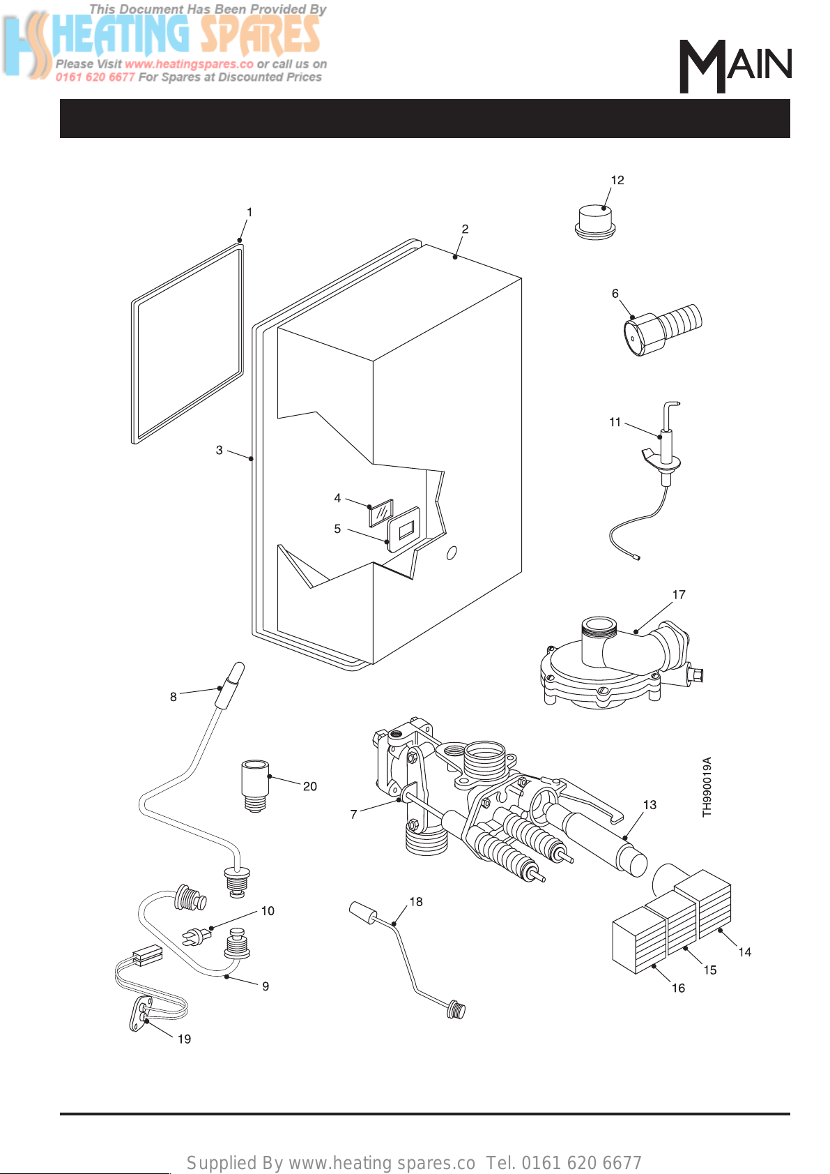
Short List of Spares
6. Shor t List Of Spares
Fig. 49
Page 32
Supplied By www.heating spares.co Tel. 0161 620 6677
32 Part No.5000893
Short List of Spares
Drg. Ref. G.C.Part No. Descr iption. No.Off. Makers Part No.
1
2
3
4
5
6
7
8
9
10
11
12
13
14
15
16
17
18
19
20
284 957
285 907
285 910
285 908
285 909
285 513
285 678
285 930
285 929
397 688
285 931
285 679
393 492
285 934
285 935
285 936
285 691
285 937
285 942
285 956
Seal Pack - Chassis to Flue Terminal
Case Assembly
Case Seal - Self Adhesive Rubber
Viewing Aperture Seal
Viewing Aperture Glass
Injector N.G. 1.2mm
Flame Safety Device Assembly
Thermocouple - Special
Thermocouple Connection - Special
Interrupter Insert
Electrode Assembly
Pilot Injector - Special
Piezo Unit - RV 1174
Igniter 'IGN' Button
Starter 'ON' Button Assembly
Stop 'OFF' Button Assembly
Water Governor Assembly - Mersey Super
Water Governor Assembly - Medway Super
Water Governor Assembly - Thames
Thermostat Assembly - Thames
Energy Cut-Off Device Assembly - includes grommets
Pressure Relief Valve Assembly - Medway Super/Thames
Pressure Relief Valve Assembly - Mersey Super
1
1
1
1
1
14
1
1
1
1
1
1
1
1
1
1
1
1
1
1
1
1
1
31/12299
10/17543
10/17501
10/17499
10/17500
19/12196
10/13477
10/17461
10/17790
10/13846
10/17493
19/12690
10/11935
10/17507
10/17540
10/17541
10/18920
10/18907
10/18900
10/13486
10/17792
10/17866
10/17865
Page 33

Supplied By www.heating spares.co Tel. 0161 620 6677
33
Part No.5000893
Washing Machine Information
This Mersey Super , Medway Super and Thames
will work in conjunction with most automatic
washing machines (pressure filled type).
1. The washing machine must incorporate a
pressure level switch to control the amount of
water required during the washing cycle and
an independent heating element, to boost the
washing temperature for certain washing
programmes above the normal 60 °C (140 °F)
temperatures produced by this instantaneous
water heater. Most modern machines use
these types of controls.
2.Washing machines which use a “TIMED FILL”
cycle are NOT suitable for use with
instantaneous water heaters.
3. Washing machines which use a “MIXING
THERMOSTAT” which attempts to mix both
hot and cold water supplies to obtain a predetermined temperature are NOT suitable for
use with instantaneous water heaters.
4. The cold water supply pressure must be at
least 1.7 bar.
5. Where a restrictor washer is fitted to the hot
water inlet of the washing machine this MUST
be removed in all cases.
6. Cold fill only type washing machines are not
affected at all by instantaneous water heaters
and may be used in the same household,
provided it is NOT connected to the hot water
supply.
INSTALLATION DIAGRAM FOR
WASHING MACHINES
Instantaneous Water Heater
Hot Outlet
to Other Taps
Isolating Taps
Cold Water Supply
1.7 bar (25 p.s.i.)
Min Pressure
Washing Machine Information
Fig. 50
Page 34
Supplied By www.heating spares.co Tel. 0161 620 6677
34 Part No.5000893
Shower Information
The Medway Super and Thames will work in conjunction
with many modern showers or bath/shower mixers. The
Mersey Super is not suitable for use with a shower
system.
Shower systems fed with an instantaneous water heater
may result in a decreased temperature range and
adjustment facility when compared with shower systems
fed from storage systems although in general a
satisfactory shower can be obtained with both manual
and thermostatic type mixer valves.
Some manufacturers supply shower systems suitab le for
use with instantaneous water heaters and give specific
instructions for installation and use. In these instances
preference should be given to the sho w er manufacturers
instructions.
For further information regarding shower systems
contact the following manufacturers quoting the make
1. Most instantaneous water heaters are
capable of supplying several outlets, but not
necessarily at the same time.
2. To obtain the best results from the shower
system the Dereve Water (Pressure)
Governor type 7052/4 should be installed to
govern the cold supply to the shower.
For local suppliers of the governor contact:
Dereve (Flow Controls) Limited,
Park Lane,
Handsworth,
Birmingham. B21 8LE.
Tel: +44 (0)121 553 7021.
Some mixer valves may not require the
fitting of a water governor, advice must be
sought from the shower manufacturer.
3. The nearer the shower is to the water heater ,
the more satisfactory will be the shower,
particularly ease of temperature selection.
4. Ideally the cold water pipes on the delivery
(outlet) side of the water governor to the
shower should not serve any other draw-off
when the shower is in use.
5. If the shower is permanently too cold
unscrew the water governor slightly, if the
shower is permanently too hot screw the
governor in slightly until a reasonable range
is achieved.
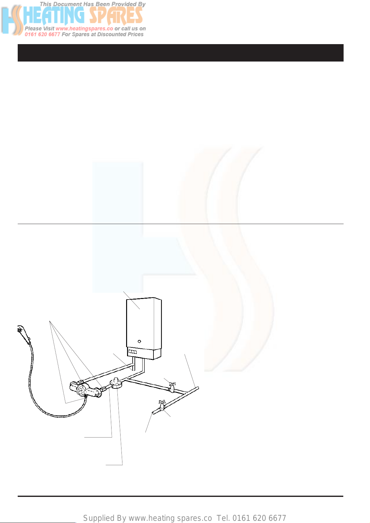
INSTALLATION DIAGRAM FOR
SHOWER SYSTEMS
Instantaneous
Water Heater
Check Valves - 3 off
(See Water Supply
Byelaws Guide)
Hot Water
Supply to
Other
Outlets
Cold Water
Supply to
Other
Outlets
Isolating
Stopcock
Mains
Stopcock
Cold Water
Mains Supply
Cold Water to
Mixing V alv e
Dereve W ater (Pressure)
Governor Type 7052/4
and model of instantaneous water heater to be used with
the shower system.
Kohler Mira Limited [www.mirashowers.com]
Cromwell Road
Cheltenham
Gloucestershire. GL52 5EP.
Tel: (0870) 2410888.
Aqualisa Products Limited [www.aqualisa.co.uk]
The Flyers Way
London Road
Westerham
Kent.TN16 1DE.
Tel: +44 (0)1959 560000
In the absence of shower manufacturers specific
instructions, the following is a general method of
installation and adjustment for shower systems:-
Shower Information
Fig. 51
Page 35

Supplied By www.heating spares.co Tel. 0161 620 6677
35
Part No.5000893
WARNING:DO NOT ATTEMPT TO AL TER THE
TEMPERATURE BY ADJUSTING THE WATER
HEATER TEMPERATURE SELECTOR - THIS
MUST ALWAYS BE SET AT ITS HOTTEST
POSITION WHEN THE SHOWER IS IN USE.
6. When non-thermostatic type mixer valves
are set with the temperature control at the
maximum hot position the water temperature
can rise to the full output of the water heater
i.e. approximately 60 °C (140 °F).
It is therefore recommended that before
stepping under the shower when operating
this type of control set the mixer to a mid
position and then gradually increase to the
desired temperature.
7. Flexible shower hoses and rigid pipes
between the mixer valve and shower head
must have a minimum bore of 3/8 in.
8. Push on type shower mixers are NOT
suitable.
9. The shower head must be of a low pressure
type and be capable of passing
approximately 13.6 l/min (3.0 gal/min) of
mixed water.
10. Flow isolation should be provided on the
supplies to the shower system to facilitate
servicing.
ADJUSTING THE SYSTEM
Two methods are suggested for setting the system depending
on whether a thermostatic or non-thermostatic shower mixer
is used.
NON-THERMOSTATIC SHOWER MIXERS
1.Turn off the cold water supply to the water heater using the
service tap supplied.
2.Tur n the mixer temperature control to the mid position.
3.Tur n the mixer flow control to maximum.
4. Turn on the cold supply to the mixer and adjust the water
governor so that the cold flow from the shower head is 7.3
l/min (1.6 gal/min) This flow can be checked using a
graduated container.The time taken for collecting 4.5 litres
(1 gallon) should be 37 - 39 seconds.
5. Turn on the cold supply to the water heater and check the
shower temperature. It should now be possible to obtain
the desired shower temperature using the controls on the
mixer.
THERMOSTATIC SHOWER MIXERS
1.Turn on both the hot and cold water supplies to the shower
mixer.
2. Turn the mixer control to the maximum position or if
graduated in degrees centigrade to 45 °C.
3. Turn the mixer flow control to maximum and adjust the
water governor so that the temperature from the shower
head is at 45 °C.
Shower Information
Page 36

Supplied By www.heating spares.co Tel. 0161 620 6677
Mersey Super - Medway Super Thames
All loose items have been packed by
the Packer identified below
Packers Stamp No.
Baxi Potterton
Brownedge Road, Bamber Bridge
Preston, Lancashire. PR5 6SN
www.potterton.co.uk
Publication No. 5000893 - Iss. 06 (01/2003)
All descriptions and illustrations provided in this leaflet have been
carefully prepared but we reserve the right to make changes and
improvements in our products which may affect the accuracy of the
information contained in this leaflet.All goods are sold subject to our
standard Conditions of Sale which are available on request.
General Enquiries (GB)
Tel. 08706 060 780
Technical (GB)
Tel. 08706 049 049
Service (GB)
Tel. 08706 096 096
Fax. 01926 410 006
Literature Request (GB)
Tel. 08706 060 623
Technical (IE)
Tel. 1850 560570
 Loading...