

®
BOOK NO, 22104
Straight
with
Flexi-Ban~d
Knife
(Mode/A)
SABRE900
SABRE800
SABRE700
Instructions
and
Parts
I
I
Cutting
Sharpener
List
Machine
iti'Jo
·~
©
1982
H.
MAIMIN
SAFETY
1.
BE SURE
operator
2,
USE
U.S.A. only I phase: Use AWG 16/3 SJ, SJT
INTERNATIONAL
3. KEEP
4. AVOID DANGEROUS ENVlRONMENT. Do
5. KEEP VISITORS AWAY. They should be kept at a safe distance from the,cutting area.
STORE
6.
7. MAINTAIN
instructions for lubricating.
8.
ALWAYS DISCONNECT MACHINE when not in use, before servicing, and when changing blades.
9.
REMOVE KNIFE KEY AND WRENCHES. The knife
starting motor.
10. AVOID ACCIDENTAL STARTING. Disconnect electrical cord before carrying machine.
connecting
I
~~·
~EEP
~KEEP
CO.,
INC.
INSTRUCTIONS
MACHINE
from electrical shock. Use a Maimin Grounded Connector (#458B,
CORRECTELECTRICAL
.
CUTTING
MACHINE
MACHINE
cord.
GUARDS IN PLACE AND
HANDS AWAY FROM CUTTING BLADE.
IS PROPERLY GROUNDED. The cutting machine should be grounded while in use to protect the
WIRING
3 phase: Use AWG 16/4 SJ,
1P
+ N +
1:
Use 3x
l,
0
3P+
J_:
~
Use
AREA
CLEAN. A cluttered table can cause accidents.
PROPERLY. When not in use, the machine should be stored in a dry location.
WITH CARE. Keep machine clean and blade sharp for best and safest performance. Follow
IN
rtJ.m'
4x
1,
0 rnm' CEE(2)61'
not
WORKING ORDER.
SJT
CEE(2)6l
use machine in a
key
and other wrenches must be removed from machine before
damp
or
#458A for 3 phase machine).
or
wet location. The work area should be well lit.
Be
sure switch
is
off
before
H. MAIMIN CO., INC.,
P.O.
Box
549 ~ Route
341,
Kent, Connecticut
06757,
U.S.A.
I.
DESCRIPTION
1.1
GENERAL
Your new Maimin Sabre straight knife machine
It
is
ready for operation.
electrical outlet
ting. The straight knife machine can
of
types
machine. However, for best results, it
minimum height
cutting blade
No. A403) acts as a protective guard for the operator so
be
should
on top
of
from vibrating.
of
materials from a
of
at
its highest position. The Presserfoot Leg
down
at
the lay when cutting in order to prevent the material
merely necessary
the correct voltage, oil it, and then begin cut-
few
the
lay be no lower than the
all times. The Presserfoot should lie lightly
be
used for cutting various
ply to the full capacity
is
recommended
is
delivered
to
connect it to an
that
bottom
of
of
(Key
that
the
the
the
1.2 FLEXIBANDS AVAILABLE
Three different grits
ening the blade:
Coarse - For hard
Medium -
Fine -
(Part
For
(Part
For
(Part
of
"FlexiBands" are available for sharp-
or
coarse materials
1450-
fine woolens, synthetics and cottons
1451
sheer fabrics, very soft materials
1452-
Box
- Box
Box
of
of
of
100)
100)
100)
1.3 BLADES AVAILABLE
The blades come in three grades and in different shapes for cutting unusual
are:
ZK-
retaining its cutting edge for a long time.
BK-
the ZK blade
TK
_:._
well. Used only for hard
glass
See back cover for complete list
cording to size, grade, shape, and quantity.
or
difficult materials. The three grades available
High Speed Steel
Carbon Alloy Steel
Treated High Speed Steel . . . Retains cutting edge very
or
heavy denim as
but
less costly.
...
Most popular blade as it wears well
...
A quality blade less durable than
or
abrasive materials such as fiber-
it
is
very expensive.
of
part numbers
of
blades ac-
II.
OPERATION
2.1
UNPACKING A NEW MACHINE
During shipment oil may have flowed onto Pulley A303 which
can cause sharpener to traverse slowly. Sharpener cycle time
1.5
seconds.
oil, disconnect power, remove Brake A342, wipe oil from
Pulley and Crank
paragraph 2-11.
If
longer, oil
is
causing Pulley to slip.
A505. Replace Brake as described in
To
is
remove
2.2 TO START
it
Fill oil cup. Attach Connector
Move switch
(International).
Caution: 3 phase
viewed from rear.
A550 from
motor
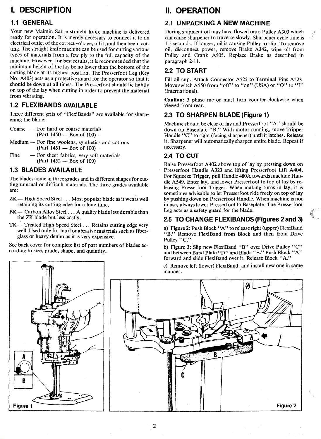
2.3 TO SHARPEN BLADE (Figure
Machine should be clear
down
on
Handle
it. Sharpener will automatically sharpen entire blade. Repeat
necessary.
Baseplate
"C"
"B."
to right (facing sharpener) until it latches. Release
A525
to Terminal Pins A523.
"off"
to
"on"
(USA)
or
"0"
to
must turn counter-clockwise when
1)
oflay
and Presserfoot
With motor running, move Tripper
"A"
should be
"I"
if
2.4 TO CUT
Raise Presserfoot A402 above top
Presserfoot Handle A323 and lifting Presserfoot Lift A404.
For Squeeze Trigger, pull Handle 480A towards machine Handle A549. Enter
leasing Presserfoot Trigger. When making turns in lay,
sometimes advisable to let Presserfoot ride freely on
by pushing down
in use, always lower Presserfoot
Leg acts as a safety guard for the blade.
Jay,
and lower Presserfoot
on
Presserfoot Handle. When machine
2.5 TO CHANGE FLEXIBANDS (Figures 2 and
a) Figure
"B."
Pulley
b) Figure
and between Band Plate
forward and slide FlexiBand over it. Release Block
c)
manner.
2:
Push Block
Remove FlexiBand from Block and then from Drive
"C."
3:
Slip new FlexiBand
Remove left (lower) FlexiBand,and install new one in same
"A"
"D"
of
lay by pressing down
to
top
of
lay by re-
top
to
Baseplate. The Presserfoot
to
release right (upper) FlexiBand
"B"
and Blade
over Drive Pulley
"E.''
Push Block
"A."
of
is
"C"
"A"
on
it
lay
not
3)
is
c
Figure
1
2
Figure 2
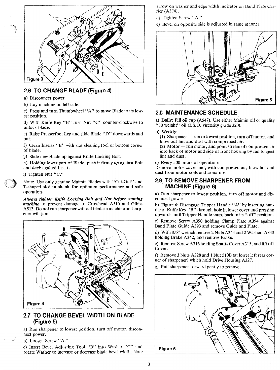
ctrrow
on
rier (A374).
d)
e)
washer and edge width indicator on Band Plate Car-
Tighten Screw
Bevel on opposite side
"A."
is
adjusted in same manner.
2.6 TO CHANGE BLADE (Figure
a) Disconnect power
b) Lay machine
c)
Press
est position.
d) With Knife Key
unlock blade.
e)
out.
f)
of
g)
h) Holding lower part
and
i) Tighten
Note: Use only genuine Maimin Blades with
T -shaped slot in shank for optimum performance and safe
operation.
Always
machine
A513. Do
ener
and
Raise Presserfoot Leg
Clean Inserts
blade.
Slide new Blade up against Knife Locking Bolt.
back against Inserts.
tighten Knife Locking
will
jam.
on
left side.
turn
Thumbwheel
"B"
"E"
with slot cleaning tool
of
Nut
"C."
to
prevent damage to Crosshead A510 and Gibbs
not
run
sharpener without blade in machine
"A"
turn
Nut
and
slide Blade
Blade, push it firmly
Bolt
4)
to
move Blade
"C"
counter-clockwise
"D"
or
"Cut-Out"
and
Nut
to
its low-
to
downwards and
bottom corner
up
against Bolt
and
before running
or
sharp-
Figure
5
2.C
MAINTENANCE SCHEDULE
a) Daily: Fill oil cup (A547). Use either Maimin oil or quality
"30
weight" oil (I.S.O. viscosity grade 320).
b)
Weekly:
(1) Sharpener -
out
blow
(2)
Motor-
into back
and
lint
c) Every
Remove
dust from
dust.
500 hours
motor
motor
lint
run
to
and
run
of
motor
cover and, with compressed air, blow lint and
coils and armature.
lowest position, turn
dust with compressed air.
motor,
and
and side
of
operation:
point stream
of
front housing by fan to eject
off
motor, and
of
compressed air
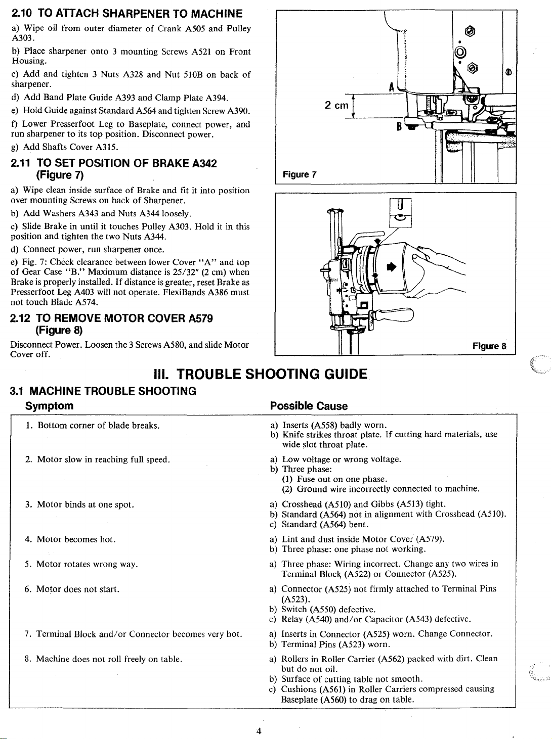
2.9 TO REMOVE SHARPENER FROM
MACHINE
a) Run sharpener
connect power.
b) Figure 6: Disengage Tripper Handle
dle
of
Knife Key
upwards until Tripper Handle snaps back to its
c)
Remove Screw A390 holding Clamp Plate A394 against
Band Plate Guide A393 and remove Guide and Plate.
d) With
holding Brake A342, and remove Brake.
e)
Cover.
f)
ner
g)
3/8"
Remove Screw A316 holding Shafts Cover A315, and lift
Remove 3 Nuts A328 and 1
of
sharpener) which hold Drive Housing A327.
Pull sharpener forward gently
(Figure
to
"B"
wrench remove 2 Nuts A344 and 2 Washers A343
6)
lowest position, turn
through hole in lower cover
Nut
SlOB
to
off
motor
"N'
by inserting han-
"off"
(at lower left rear cor-
remove.
and
position.
and dis-
pressing
off
Figure 4
2.7
TO
CHANGE
(Figure
a) Run sharpener to lowest position, turn
nect power.
b) Loosen Screw
c)
Insert Bevel Adjusting Tool
rotate Washer
to
5)
"A."
increase
BEVEL
WIDTH
"B"
or
decrease blade bevel width. Note
ON
off
motor, discon-
into Washer
BLADE
"C"
and
3
Figure 6
2.10 TO ATTACH SHARPENER TO
a) Wipe oil from outer diameter
A303.
b) Place sharpener onto 3 mounting Screws
Housing.
c) Add and tighten 3 Nuts A328 and
sharpener.
d) Add Band Plate Guide A393
e) Hold Guide against Standard A564 and tighten Screw
f)
Lower Presserfoot Leg to Baseplate, connect power, and
run sharpener
g)
Add Shafts Cover A315.
2.11
a) Wipe clean inside surface
over mounting Screws on back
b) Add Washers A343 and Nuts A344loosely.
c) Slide Brake in until it touches Pulley A303. Hold it in this
position and tighten the two Nuts A344.
d) Connect power,
e) Fig. 7: Check clearance between lower Cover
of
Gear Case
is
Brake
Presserfoot Leg
not
touch Blade A574.
to
its
top
position. Disconnect power.
TO SET POSITION
(Figure
properly installed.
7)
run
sharpener once.
"B."
Maximum distance
A403 will
not
of
Crank A505 and Pulley
and
Clamp Plate A394.
OF
BRAKE A342
of
Brake and fit it into position
of
Sharpener.
If
distance
is
operate. FlexiBands A386 must
MACHINE
A521
on
Front
Nut
510B
on
back
A390.
"A"
and
is
25/32"
(2
greater, reset Brake as
top
em) when
2.12 TO REMOVE MOTOR COVER A579
(Figure
Disconnect Power. Loosen the 3 Screws A580, and slide
Cover off.
8)
Motor
of
Figure 7
Figure 8
3.1
MACHINE
TROUBLE SHOOTING
Symptom
1.
Bottom corner
2.
Motor
slow in reaching full speed.
3.
Motor
binds
Motor
4.
5.
6.
7.
8.
becomes hot.
Motor rotates wrong way.
Motor
does
Terminal Block
Machine does not roll freely on table.
of
at
one spot.
not
start.
and/or
blade breaks.
Ill. TROUBLE SHOOTING GUIDE
Possible
a) Inserts (A558) badly worn.
b) Knife strikes throat plate.
wide slot throat plate.
a) Low voltage
b) Three phase:
(1)
Fuse
(2)
Ground
a) Crosshead
b) Standard (A564)
c)
Standard (A564) bent.
and
a) Lint
b) Three phase: one phase not working.
a) Three phase: Wiring incorrect. Change any two wires
Terminal
a) Connector (A525) not firmly attached to Terminal Pins
(A523).
Connector becomes very hot.
b) Switch
c)
a) Inserts in Connector (A525) worn. Change Connector.
b) Terminal Pins (A523) worn.
a) Rollers in Roller Carrier (A562) packed with dirt. Clean
b) Surface
c)
(A550) defective.
Relay (A540)
but do
not
Cushions (A561) in Roller Carriers compressed causing
Baseplate
of
Cause
If
cutting hard materials, use
or
wrong voltage.
out
on one phase.
wire incorrectly connected to machine.
(A510) and Gibbs (A513) tight.
not
in alignment with Crosshead (A510).
dust inside
Bloc~
oil.
cutting table
(A560)
Motor
Cover (A579).
(A522)
or
Connector (A525).
and/or
Capacitor (A543) defective.
not
smooth.
to
drag on table.
in
4

3.2 SHARPENER TROUBLE SHOOTING
Symptom
I.
No bevel on one side
2. Bevel
3. Sharpener runs
4.
5.
6. Band cut
7. Block (A397) falls
8. Block (A397) pivots, twisting band.
9.
10.
II.
12.
13.
14.
15. Presserfoot Leg does
16.
not
high enough
Sharpener does
Sharpener does
off
by blade.
Sharpener runs slowly.
Sharpener overruns
Sharpener runs continuously.
Sharpener runs only when tripper handle
Sharpener jams.
Presserfoot Leg (A403) does not move freely.
Safety
not
working.
but
not
not
bands
run
run
off
top
of
blade.
on
but
and
during
position.
not
hold.
blade.
do
not rotate.
bands rotate.
bands
do
not
band
changing.
rotate.
is
held.
Possible
a) Idler Pulley (A396) needs oil.
b) Broken Torsion
c)
Band Plates (A381, A387)
d) Bands
(A381, A387).
a) Cam (A515, A516) out
Square Shaft Gear (A336) broken.
a)
b) Retaining Ring
c)
Clamp (A364)
d) Cluster Gear
a) Keeper
b) Boat
a) Presserfoot Leg
Oil
b)
c) Retaining Ring (A320) missing.
d) Cluster Gear
e)
Worm (A311) broken.
a) Band Plate
a) Retaining Ring
.Stud (A383) broken.
a)
a)
Oil
b) Band Plate Guide (A393)
(A564).
a)
Brake (A342)
b) Screw (A363)
Screw (A363)
a)
(A367).
b) Screw (A363) missing.
c)
Retaining Ring (A345) missing.
Spring (A341) broken.
d)
a)
Spring (A357) broken.
Spring Pin (A359, A313) broken.
b)
a) Sharpener run without knife in machine.
b) Boat
c) Diamond
Sharpener
a)
b) Dirt
c) Brake (A342)
a) Lock
b)
Trigger Spring (A322) broken.
a) Leg Guide
b)
Safety Pin (A347) missing.
c)
Screw
Cause
Spring (A382, A388).
do
not
cross due
(A338) missing.
out
of
(A332) broken.
Plate
(A334) loose.
(A333) worn.
on
Crank
(A505)
(A332) broken.
(A387) defective.
on
Crank
(A505)
too
too
too
(A333) broken.
Shaft (A356) bent.
not
or
oil in Leg Guide (A354).
too
(A330) loose
(A354) broken.
and
Nut (327A) loose
position.
(A403)
and/or
(A398) missing.
and/or
far from Pulley (A303).
low.
low - less than
at
top
position.
close to Pulley.
on
Shaft (A325).
do
not
rotate freely.
to
interference
of
position.
not
down completely.
Pulley (A303).
Pulley (A303).
too
tight against
1"
or
missing.
above
of
Band Plates
Standard
Gear
Case
5

A315B
MODEL A SHARPENER
A315A
'309A:3QB
A307A306
OS\
~
A305
A301
~
A304
A30~~
~
~~
A302
342
A
01
A:3QO
A377
A378~
A403
A391A
·~b::
481J
·~~
490481F~~r
480G
480H
481A
A379~
6

PARTS
LIST
1
r
~-~
KEY PART
NO.
A300
A301
A302
A303
A304 23235
A305
A306
A307 23232
A308
A309
A310
A311
A312
A313
A314
A314A
A315
A315A
A315B
A316
A317
A318
A319
A320
A321
A322
A323
A324
A325
A326
A327
A327A
A328
A329
A330
A331
A332
A333
A334
A335
A336
A337
A338
A339
A340
A341
A342
A343
A344
A345
A346
A346A
A347
A348
A349
A350
A351
A352
A353
A354
A355
A356
A356A
A356B
A357
A358
A359
A360
NO.
838N
1499D
1498A
1498
23196
23231
839W
23234
23066
23067
23036
23267
23005
402BK
23229A
23229B
23229C
23229D
402BF
402BJ
23056
481F
23192
23193
23017
23219
23233
492
23047
490
23049
23053
23274
510A
510B
23252
23271
23050
23243
23189
23119
23120
23259
23203
23273
1277
23251
23019
23031
23200
23007
510B
23016
23284
23289
23283
23011
23013
23190
23054
23205
23258
23207
23122
23093A·W Diamond
23286
23287
23008
23007
23267
23211A
23211B
23211C
23211 D
DESCRIPTION
1/4-20 Hex
Nut,
Washer, 1/4 x 9/16 x 3/64
Clamp
only
Pulley
Bushing
Worm
Shaft
Bearing, flanged .314 x .439 x 3/4
End Cap
Washer, .32 x
Retaining Ring,
Spring Pin,
Worm
Push
Rod
Spring Pin, 1/16 x 3/8
Cam
Tapered Plug #12
Shafts
Cover,
Shafts
Cover,
Shafts
Cover,
Shafts
Cover.
Tapered Plug #9
Tapered Plug
Screw,
Screw, 1/4 x 3/8
Cartridge w/Worm
Cartridge
Spring
Retaining Ring,
Bearing .314 x .44 x 1/2
Trigger
Presserfoot Handle
Screw,
Shaft
Tripper Handle
Housing
Drive
Screw, 10
Nut, 10·32 Hex
10·32
Nut,
Screw, 8 x 5/8
Lock
Cup
Cluster
Boat
Keeper Plate
Screw, 6 x 1/4
Square
Block
Gear
Retaining Ring,
Screw,
Screw,
Spring
Brake
Washer, 13/64 x 7/16 x 1/32
Nut,
10·32 Hex
Retaining Ring, 5144·25
Link
Assembly
Washer, .257 x
Safety Pin
Pin
Spring Pin,
Tripper
Screw,
Leg Keeper
Screw, 4 x 5/16
Leq
Guide
Screw, 6 x
Screw,
11" & 14" Machines Only
Washer, Nylon,
11"
& 14" Machines Only
Spring
Washer, 13/64 x 7/16 x 1/32
Spring Pin, 1/16 x 3/8
Square Shaft,
Square Shaft,
Square Shaft,
Square Shaft,
1/2
x 1/32
5100-31
7164
x 1/2
5" -8"
9"
11
"
14"
#"16
1/4 x 1/2
Spring
5/16 x 3/8 Set
Gear
Shaft
10
6 x 5/8 Socket Cap
6 x 1/8
10 x 1/2
Always
Socket
Cap
Shoulder
only
x
Socket
x 3/4
1/4
Shaft
& Pulley
5555·23
with
Bushings
1/2
Socket Set Cup
(3)
Socket
Hd. Cap
(2)
Gear
with
Bushings
5100-50
Slot
Set Flat Pt.
(2)
w/23283
9116 x 1132
3/32 x 5/16
Socket
Set Cup
(2)
Button Hd. Socket Cap
Assy
(give size & stroke)
Button Hd. Soc. Cap
.191 x 17132
5"-
8"
9"
11"
14"
Give
Machine
Order
By
(2)
(2)
(2)
x 3/16
PART
(4)
SERIAL
NUMBER-
KEY PART
NO.
A360A
A361
A362 23226
A363 23290
A364
A365 824T
A366
A367
A368 23086
A369
A370 23210
A371
A372
A373
A374
A375
A376 23084
A377 23098
A378
A379
A380
A381
A382
A383
A384 23116
A385 23117
A386
A387
-
A388 23109
A389 23223
A390
A391
A391A
A392
A393
A394
A395
A396
A397
A398
A399
A400
A401
A402
A403
A404
A405
NUMBER
Not
NO.
23277 Screw, 6 x 3/8 Knurled Nylon
23244 Cover
23212 Clamp w/23263
23263
510B
23275
23091A
23086
23208
23209
23276
23261
23099
23097
23227
23165
23110
23115
1450
1451
1452
23164
23019
23122
402BH Tapered
23225
23250
23272
23282
23249
23114
23293
23111
23288
23112
23172
23116
23040
23040A Presserfoot,
23040B
23039A
23039B
23039C
23039D
23039E
23039F
23039G
824
23122
323PJ
480A
48QD
480E
480G
480H
480Y
481A
481B
481C
481J
481H
481F
490
1256
23292 Ball,
When
Key
Number
SQUEEZE TRIGGER ASSEMBLY
Ordering
DESCRIPTION
Screw, 6 x
Screw,
Screw, 10 x
Screw, 6 x 3/8 Socket Cap
Nut, 10-32 Hex
Gear Case
Bearing, flanged .252 x .377 x 1/4
Bearing, flanged .252 x .377 x 1/2
Drive Gear
Bearing, flanged .252 x .377 x
Driven Gear,
Driven Gear, right
Band
Washer, 3/16 x
Screw,
Rubber Tire
Drive Pulley
Screw,
Retaining Ring
Band
Spring,
Stud,
Spring Pin, 3/32 x 1/4
Spring
FlexiBand,
FlexiBand,
FlexiBand,
Band Plate,
Spring,
Eccentric
Screw,
Screw, 6 x 1/4
Washer(2)
Band Plate Guide,
Band
Band
Clamp
Stud,
Pulley, Idler, w/Bushing
Block
Retaining Ring,
Screw, 8 x 1/2
Screw, 4 x 1/4 Socket Hd. Cap
Spring Pin, 3/32 x 1/4
Presserfoot,
Presserfoot, 14"
Presserfoot Leg -
Presserfoot Leg,.--
Presserfoot Leg -
Presserfoot Leg -
Presserfoot Leg -
Presserfoot Leg -
Presserfoot Leg -
Presserfoot
Sere','/, 6 x
Pin
Handle
Bracket
Screw,
Collar w/481A and 480H
Spring
Squeeze
Screw, 6 x
Cam
Cam
Presserfoot Lever
Presserfoot Lever
Screw, 1/4 x 3/8 Shoulder
Screw,
Spring Pin, 3/32 x 1/2
Parts.
1/4
10
x 1·1/2 Fillister Hd.
1/2
with
left
Plate Carrier
10 x 1/2
(2)
(2)
4 x
118
Soc. Set
Plate,
right
Torsion, right
118
X 1-1/8
(2)
CoarseMediumFine-
left
Torsion,
Stud
6 x 5/8 Socket Cap
Plate Guide,
Plate Guide,
Plate ·
Idler
(2)
wl
5/8
(2)
Button
Plug
#14
Pulley
Button
5"9" & 11
Lift
114
Button
Assembly
10
x 5/8 Socket Cap
Trigger
1/8
Round Hd.
480E and 323PJ
5/16 x 3/8 Set
Socket Hd. Cap
Slot
Set
Flat
(4)
Bushings
w/Bushings
112
x 3/64
Socket Hd. Cap
Flat
(2)
(2)
100/box
100/box
Hd
(2)
8"
11"
(2)
(2)
Hd.
(2)
(2)
"
Hd.
(2)
Pt.
5100-25
(4)
100/box
left
5"9",
14"
(2)
5144-12
8"
"
5"
6"
7"
8"
9"
11
14"
Assy w/4800 and
w/490
(2)
Pt.
1/4
(2)
;)J7
ot/tfi?
481
J
30·"
...
7
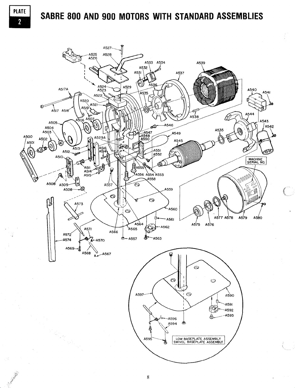
SABRE
800
AND
900
MOTORS
WITH
STANDARD
ASSEMBLIES
~
~/
A572:N
A574
A56
.~A570
!:\
A568
~A567
8

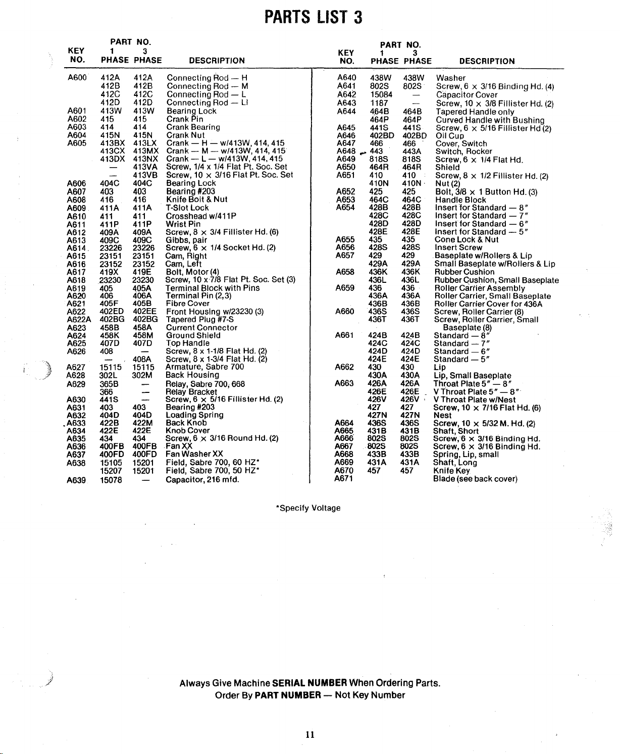
PARTS
LIST
2
KEY
NO. PHASE PHASE
A500
A501
A502
A503
A504 415N 415N Crank
A505
A506 404C
A507 403
A508 416
A509
A510
A511
A512 409A 409A
A513 409C 409C
A514 23226
A515 23151 23151
A516 23152
A517 419Z 419Z
A517A 419R
A518 402W
A519
A520 402L 402L
A521
A522 405
A523 406
A524
r·
I
A525 458B
A526 458K 458M
A527
A528
A529 402CC
A529A 402BG
A531
A532
A533
A534
A535 497P
A536
A537
A538
A539
A540 365G
A541 802S
A542 824S
A543
A544
A545
A546
PART NO.
1 3
412A
412B
412C
4120
413W
415
414
413BX 413LX
413CX 413MX Crank w/413W, 414, 415-M
4130X
413EX
411A
411
411P
419ZB
802S
23230 23230
405F 405B
408A
4070
468J
468C 468C
4680
468A
468S
400J
3020C
30200
15097 A 15202A Stator, Sabre 800, 60 HZ*
15211
15222 Stator,
15226 Stator, Sabre 900,
365E
3650
365H
15079
15076
3020A
15223
15224
441S 441S
412A
412B
412C
4120
413W
415 Crank Pin
414 Crank Bearing
413NX Crank w/413W,
413RX Crank w/413W, 414,
413VA Screw, 1/4 x
413VB Screw,
404C
403
416
411A T-Siot
411
411P
23226 Screw, 6
23152
419ZB Bolt,
419R Washer,
402W
802S
405A
406A
458A
408B Screw, 8 x 2 Flat Hd.
4070
402CO
402BG
468J
4680
468A
468S
497P
400J
3020C
30200
15202A Stator, Sabre 800, 50 HZ* A574 Blade (see back cover)
483
3020B
15223
DESCRIPTION
Connecting
Connecting
Connecting
Connecting
Bearing
Crank w/413W,
Bearing
Bearing #203
Knife
Crosshead w/411 P
Wrist
Screw, 8 x 3/4
Gibbs, pair
Cam, Right
Cam, Left
Bolt,
Windguard
Screw, 6 x 3/16
Guard 424B 424B Standard -
Oil
Screw,
Terminal
Terminal Pin (2,3)
Fibre Cover
Current
Ground
Screw, 8 x 1-3/4 Flat Hd.
Top Handle
Front Housing w/23230
Tapered Plug
Thumbwheel w/Shaft
Spring 427 427
Thumbwheel
Thumbwheel
Screw, 6 x 7/8 Socket Hd.
Support
Fan
Adaptor
Spring Pin, 5 x 20
Relay, Sabre
220/50/1, 110/50/1
Relay, Sabre
Relay, Sabre 900,
Relay, Sabre
Voltage Change Panel,
Screw, 6 x 3/16
Screw,
Capacitor
Capacitor
Spider
Armature Assembly, Sabre
Armature Assembly, Sabre
Screw, 6 x 5/16
Rod-
H
Rod-
M
Rod - L
Rod-~
Lock
Nut
10
x 3/16 Flat Pt. Soc. Set
Lock
Bolt
&Nut
Lock
Pin
x
1/4
10
x 3-1/2, Sabre 800
10
x 3-3/4, Sabre 900
.200 x 3/8 x .036 A562 436 436
10
x·
718
Block
Connector
Shield
Washer
Ring
Sabre 900,
6 x 3/8
161
270
Ll
414,
415-H
414,
415-L
415-LI
1/4
Flat
Pt.
Fillister
Socket Hd.
Flat Pt. Soc. Set
#7-S
Support
Assembly
800,
800, 703 ·-220/60/1
900,
Binding
mfdmfd-
Hd.
Binding
with
Pins
(3)
mm
(4)
6.0
HZ*
50
HZ*
692-
716
- 60 HZ A580 23122 23122 Screw, 6 x
710.'-
Binding
Hd.
Sabre800 440M 440M
Sabre 900
Fillister
KEY
NO.
A547
A548
A549
A550 442G
A551
A552
Soc. Set
(6)
(2)
(4)
(4)
Hd.
(2)
(3)
(2)
120/60/1, A577
50' HZ
50
HZ .
Hd.
(2)
800
900 A596 433B 433B Spring, Lip, small
Hd.
(2)
A553
A554
A555 464C
A556
A557 435 435 Cone
A558 428A 428A Insert
A559 428S
A560
A561
A563
A564
A565 430 430
A566
A567
A568 431B 431B
A569
A570
A571
A572
A573 457 457
A575
A576
A578
A579
A590
A591
A592 436E
A593 340 340
A594
A595
A597 430B 430B Lip,
PART NO.
1 3
PHASE PHASE DESCRIPTION
Oil
402BO 402BO
466E
466B
464B 464B
464P
443
464R 464R
818S
410 410
410N
425
428B 428B
428C
4280
428E
428H
428M 428M
429
436K 436K Rubber
436S 436S Screw,
424A
424C 424C
4240 4240
424E 424E
424H 424H
424M
426A 426A
426B 426B
426C 426C
426E 426E V Throat
426F 426F V Throat
426V
427N 427N
436S 436S Screw, 10 x 5/32 M Hd.
802S
802S
433B
431A
403 403 Bearing #203
4040
404E
404F
3020B
429B
440A
436L
431C
802S
466E Cover,
464P
442G
818S
410N
464C
425
428C
4280
428E
428H
428S
429
424A
424M
426V
802S
802S Screw, 6 x 3/16
433B
431A
4040
404E
404F
3020B
429B
440A Swivel Baseolate
436L Cushion,
'436E
431C Axle
802S
Cup
Switch,
USA-120V)
Switch,
Cover,
(USA-120V)
Tapered Handle
Curved
Switch,
Switch,
(USA-120V)
Shield
Screw, 6 x
Screw, 8 x 1/2
Nut
(2)
Handle
Bolt, 3/8
Lock & Nut
for
Insert
for
Insert
for
Insert
for
Insert
for
Insert
for
Insert
for
Insert
Screw
Baseplate
Cushion
Roller Carrier
10 x 5/32 M Hd.
StandardStandard-
StandardStandardStandard StandardLip
Throat
Plate -
Throat
Plate -
Plate, Wide
Throat
V Throat Plate w/Nest
10 x 7/16 Flat Hd.
Screw,
Nest
Shaft,
Short
Screw, 6 x 3/16
Spring,
Up,
Shaft, Long
Knife
Key
Loading
Retaining
Lock
Screw
Motor
Cover
Low
Baseplate
Roller Carrier, Low
Swivel Roller Assembly (rear)
Screw, 10 x 1/8 M Hd.
Screw, 6 x 3/16
Low
Sabre 800 (except
Sabre 900 & Sabre 800
w/Bushing
1/4
Flat Hd.
Fillister
x 1
Button
Standard Standard Standard StandardStandard StandardStandard-
with
Rollers & Lip
Assembly
9"
8"
7"
6"
5"
11
"
14"
5" -8"
9"
Binding
Binding
Small
Ring-
114
Button
with
BindingHd.
only
Hd.
Slot-
5"-
9"-
5008-156
Rollers &
with
1-:landle
Sabre 800 (except USA-120V)
Sabre 900 & Sabre 800
Block
PlatePlate-
Spring
Small
Hd.
(2)
(3)
9"
8"
7"
6"
5"
11"
14"
5"-
8"
14"
Hd.
Hd.
Hd.
(3)
Lip
Rollers &
8"
Lip
Always Gi\te
Order By PART
Machine
*Specify
SERIAL NUMBER When Ordering Parts.
Voltage
NUMBER-
9
Not
Key
Number

SABRE
A623
700
MOTOR
A626--J'i
A625~-
A624
--:~I
I
~
~
'
,,
" •
U
I
L
WITH
STANDARD
ASSEMBLY.
1-tL
A633 A634
A600
A671
10
PARTS
LIST
3
KEY
NO.
ASOO
A601 413W 413W Bearing Lock
A602
A603 414 414 Crank Bearing
A604 415N 415N Crank
A605 413BX 413LX
A606
A607 403
A608
A609 411A
A610
A611
A612
A613 409C
A614. 23226
A615 23151
A616 23152
A617 419X
A618
A619
A620
A621
A622
A622A
A623 458B
A624 458K
A625
A626
A627 15115 15115
A628
A629 365B
A630
A631
A632
.A633
A634
A635
A636
A637
A638
A639
PART NO.
1
PHASE PHASE
412A 412A
412B
412C 412C
4120
415 415
413CX 413MX
4130X
404C
416
411
411P
409A
23230 23230
405
406
405F 405B Fibre Cover
402EO
402BG 402BG
4070
408
302L
366
441S
403
4040
422B 422M
422E
434 434
400FB
400FO 400FO
15105 15201
15207 15201
15078
3
DESCRIPTION
412B
4120
413NX
413VA
413VB
404C
403
416
411A
411
411P
409A
409C
23226
23151 Cam, Right
23152
419E
405A
406A
402EE
458A Current
458M Ground
4070
408A
302M
403
4040
422E
400FB
Connecting
Connecting
Connecting
Connecting
Crank
Pin
Nut
CrankCrankCrank-
Screw,
1/4 x
Screw,
10
Bearing
Bearing #203
Knife
T·Siot
Crosshead w/411 P
Wrist
Screw,
Gibbs,
Screw, 6 x 1/4
Cam,
Bolt,
Screw, 10 x·7/8
Terminal
Terminal Pin (2,3) 436A 436A
Front Housing w/23230
Tapered Plug #7-S 436T 436T
Top Handle 424C
Screw,
Screw,
Armature,
Back
Relay,
Relay Bracket
Screw,
Bearing #203
Loading Spring
Back
Knob
Screw, 6
Fan
Fan
Field, Sabre 700,
Field, Sabre 700, 50
Capacitor, 216
Lock
Bolt & Nut
Lock
Pin
8 x 3/4
pair
Left
Motor
Connector
Shield
8 x 1-1/8 Flat Hd.
8 x 1-3/4 Flat Hd.
Housing
Sabre 700; 668
6 x 5/16
Knob
Cover
XX
Washer
HML-
Block
.x
KEY 1 3
NO. PHASE PHASE
Rod - H
Rod - M
Rod - L A642 15084
Rod - Ll
w/413W, 414,415
w/413W, 414,415
w/413W, 414,415
1/4
Flat Pt. Soc. Set
x 3/16
Flat
Pt. Soc. Set
Fillister
Socket
(4)
Flat Pt. Soc. Set
with
Sabre 700
3/16 Round Hd.
XX
mfd.
Pins
.
Fillister
60HZ*
HZ*
Hd.
Hd.
(3)
(2)
(2)
Hd.
(6)
(2)
(3)
(2)
(2)
A640
A641
A643 1187
A644
A645
A646 402BO 402BO Oil
A647 466
A648
A649
A650
A651
A652 425
A653 464C 464C Handle
A654 428B 428B
A655 435
A656 428S 428S
A657 429 429
A658 436K
A659 436
A660 436S
A661
A662 430
A663 426A 426A
A664 436S
A665 431B 431B
A666
A667 -802S
A668
A669 431A 431A Shaft, Long
A670
A671
438W 438W
802S
4,64B
464P 464P
441S 441S
... 443
818S 818S
464R 464R
410
410N
428C 428C
4280
428E 428E
429A 429A
436L
436B 436B
424B
4240
424E
430A
426E
426V
427 427
427N 427N
802S 802S Screw,
4338
457
PART NO.
802S Sc;rew,
464B
466 Cover,
443A
410
410N ·
425
4280
435
436K Rubber Cushion
436L
436
436S Screw, Roller
424B
424C Standard -
4240
424E
430
430A
426E
426V ·
436S Screw, 10
802S
4338 Spring, Lip, small
457
Washer
Capacitor
Screw, 10 x 3/8
Tapered Handle
Curved Handle
Screw,
Cup
Switch, Rocker
Screw,
Shield
Screw,
Nut(2)
Bolt, 3/8
Insert
Insert
lnsertfor
Insert
Cone
Insert
Baseplate
Small
Rubber Gush ion, Small Baseplate
Roller
Roller
Roller Carrier Cover
Screw, Roller Carrier, Small
Baseplate
Standard Standard-
Standard-
Lip
Lip, Small Baseplate
Throat
V
Throat
Throat
V
Screw, 10 x 7/16
Nest
Shaft,
Screw, 6 x 3/16
Knife
Blade (see back cover)
DESCRIPTION
6 x 3/16
6 x 5/16
Switch
6 x 1/4
8 x 1/2
Block
·for Standard for
for
Lock & Nut
Screw
Baseplate
Carrier
Carrier, Small Baseplate
Plate
Short
6 x 3/16
Key
Binding
Cover
Fillister
only
with
Fillister
Flat
Fillister
x 1
Button
StandardStandardStandard -
w/Rollers &
w/Rollers & Lip
Assembly
Carrier
(8)
8"
7"
6"
5"
5"-
Plate
Plate
8"
5" -8"
w/Nest
Flat
x 5/32 M. Hd.
Binding
Binding
Hd.
Hd.
Bushing
Hd
Hd.
Hd.
Hd.
(3)
8"
7"
6"
5"
Lip
for
436A
(8)
Hd.
(6)
(2)
Hd.
Hd.
(4)
(2)
(2)
(2)
*Specify
j
Always Give Machine SERIAL NUMBER When Ordering Parts.
Voltage
Order By PART NUMBER -
11
Not
Key Number
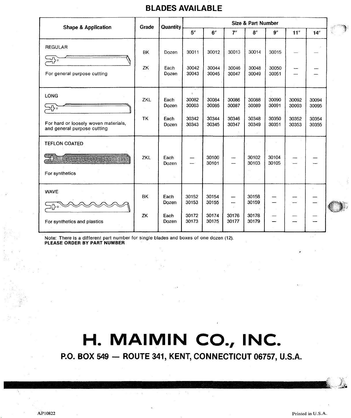
BLADES
AVAILABLE
Shape
& Application
REGULAR
~
~
For general purpose cutting
LONG
~
~
For hard or loosely woven materials,
and general purpose cutting
TEFLON
For synthetics
COATED
Grade
~
'~
BK
ZK
ZKL
TK
ZKL
Quantity
Dozen
Each 30042
Dozen
Each 30084
Dozen
Each
Dozen
Each
Dozen
5"
30011
30043
30082
30083
30342 30344
30343
30012
30044
30045
30085
30345
30100
30101
6"
Size & Part
7"
30013
30046
30047
30086
30087
30346
30347
Number
8"
30014
30048 30050
30049
30088
30089
30348
30349
30102
30103
9"
30015
30051
30090
30091
30350
30351
30104
30105
11"
30092
30093
30352
30353
14"
30094
30095
30354
30355
WAVE
20~
For synthetics and plastics
Note: There is a different part number for single blades and boxes of
PLEASE ORDER
P.O.
BY
PART NUMBER
H.
BOX
MAIMIN
549-
ROUTE
BK
ZK
Each
Dozen
Each
Dozen
341,
30152 30154 30158
30153
30172
30173
KENT,
CONNECTICUT 06757, U.S.A.
30155
30174
30175
one
dozen
30176
30177
(12).
CO.,
30159
30178
30179
INC.
f
AP10822
Printed
in
U.S.A.
 Loading...