


H~Jaaimin
Co.,
Inc.
119West40thst.,NewYork,
N.Y.
1oo1su.s.A.
BOOK
NO.
22101
~'
'o,',:~':,~;-:,;,'::::';~',::~{
'",_
,'
;'>'
o;:\"''"
Edition 5
© 1980 H.M.C.

SAFETY
INSTRUCTIONS
for
Maimin Cutting Machines
1.
BE SURE MACHINE IS PROPERLY GROUNDED
The cutting machine should be grounded while in use
to
protect the operator
from electrical shock. Surrounding the Terminal Pins
is
a Ground Shield which
is
designed to be used with a Maimin Grounded Connector (#458B, or
#458A
for 3 phase machine).
See
tag supplied with Connector for wiring instructions.
2.
USE CORRECT ELECTRICAL WIRING
U.S.A. ONLY 1 phase:
Use
AWG
16/3 SJ, SJO, SJT
3 phase:
Use
AWG
16/4 SJ, SJO, SJT
INTERNATIONAL 1P+N+b:
Use
3x1,0 mm2 CEE(2)61
3P+f:-
Use
4x1,0 mm2 CEE(2)61
3.
KEEP CUTTING AREA CLEAN
A cluttered table can cause accidents.
4.
A VOID DANGEROUS ENVIRONMENT
Do
not use machine in a damp or wet location.
The work area should be well lit.
5.
KEEP VISITORS AWAY
They should be kept at a safe distance from the cutting area.
6. STORE MACHINE PROPERLY
When
not in use, the machine should be stored in a dry location.
7.
MAINTAIN MACHINE WITH CARE
Keep machine clean and blade sharp for best and safest performance.
Follow instructions for lubricating.
8. ALWAYS DISCONNECT MACHINE:
- when not in use
-before
servicing
- when changing blades
9. REMOVE KNIFE KEY AND WRENCHES
The knife key and other wrenches must be removed from machine before
starting motor.
10. AVOID ACCIDENTAL STARTING
Disconnect electrical cord before carrying machine.
Be
sure switch
is
off
before connecting cord.
11. KEEP GUARDS IN PLACE AND IN WORKING
ORDER
12. KEEP HANDS AWAY FROM CUTTING BLADE

Contents
SECTION I Description
1-1. General
1-2.
Stones Available
1-3. Blades Available
SECTION II Operation
2-1. To Start
2-2.
To Cut
2-3. To Sharpen Blade
2-4. To Shift Edge Control Arm
SECTION
Ill
Care and Maintenance
3-1. Schedule
3-2. To Oil
3-3. To Clean Stones
3-4. To Change Stones
3-5. To Change Blade
3-6. To Clean
Inserts
3-7. To Clean Commutator
3-8. To Clean Sharpener
3-9. To Clean
Motor
3-10. To Clean Rollers
SECTION IV Trouble Shooting Guide
4-1. Sharpener Trouble Shooting
4-2. Machine Trouble Shooting
SECTION V Adjustments and Repairs
5-1. Sharpener
(a)
Guide Spring Adjustment
(b) Edge Control Arm Adjustment
(c)
Pulley Brake Adjustment
(d)
Presserfoot Leg Adjustment
(e)
Pulley Rubber Replacement
(f)
Stone Carrier Adjustment
(g)
Sharpener Removal
(h)
Sharpener Disassembly
(i)
Slide Disassembly
(j) Frame Disassembly
(k) Sharpener Assembly
5-2. Machine
(a) To Change Carbon Brushes
(b) To Adjust Crosshead and Gibbs
(c) To
Set the Position of the Standard
(d) To Replace the Inserts
(e) To Remove the Crank
(f) To Replace the
Motor
Bearings
(g) To Replace Crank
Pin Bearing
(h) To Reassemble Motor
SECTION
VI
Parts
List
Plate
1.
Sharpener Slide Assembly
Plate
2.
Sharpener Frame Assembly
Plate
3.
Machine Assembly
2
2
2
3
3
3
3
3
4
4
4
4
4
5
5
5
5
5
6
7
7
7
7
7
8
8
8
9
9
9
9
9
9
9
10
10
10
11
11
11
12
14
16
Instruction~
and
Parts
List
MaiminModeiK

SECTION
I
DESCRIPTION
1-1. GENERAL
Your new
Maimin
"POWR"
straight
knife
machine
is
delivered
ready
for
operation.
It
is
merely
necessary
to
connect
it
to
an
electrical
outlet
of
the
correct
voltage,
oil
it, and
then
begin
cutting. The
straight
knife
machine
can
be
used
for
cutting
various
types
of
materials
from
a few
ply
to
the
full height of
the
standard.
However,
for
best
results,
it
is
recommended
that
the
minimum
height
of
the
lay
be
no
lower
than
the
bottom
of
the
cutting
blade
at
its
high-
est
position.
On
the
left
side
of
the
sharpener
you
will
note a
lever -the
Edge
Control
Arm
(Key
No.
K136B)* - which
permits
sharpening
of
either
a rough
or a smooth
edge on the
blade
for
cutting
different
types
of
materials.
The
presserfoot
leg
(Key
No.
K10)
acts
as a pro-
tective
guard
for
the
operator
so
that
it
should
be
down
at
all
times.
The
presserfoot
should
lie
lightly
on top of
the
lay
when
cutting
in
order
to
prevent
the
material
from
vibrating.
1-2.
SHARPENING STONES AVAILABLE
There
are
three
different
grits
of
sharp-
ening
stones
(Key
No.
K15)
available
for
use
in
this
machine:
#60
grit -coarse.
Recommended
for
hard
and
coarse
materials.
Can
be
used
on
ZZT
and
ST
blades.
#100
grit
- fine.
Recommended
for
fine woolens,
syn-
thetics
and cotton. Can
be
used
on
all
blades.
#150
grit -very
fine.
Recommended
for
sheer
fabrics
and
very
soft
materials.
Can
be
used
on
BT
and
ZZT
blades.
1-3.
BLADES
AVAILABLE
The
cutting
blades
(K234)
come
in
three
grades,
and
also
in
several
different
shapes
for
cutting
unusual
or
difficult
materials.
The
three
grades
available
are:
BK -Carbon
Alloy Steel.
A good
quality
steel
but
less
dur-
able
than
the
ZZT
blade.
ZK - High Speed
Steel.
Most
popular
blade
available
as
it
*See
Plates
1,
2,
and 3
for
key
number
identifi-
cation.
2
wears
well,
retaining
its
cutting
edge
for
a long
time.
TK -
Treated
high
speed
steel.
Used only
for
special
materials
such
as
fiberglass
and
heavy
can-
vas
that
dull the
cutting
edge
very
quickly.
Retains
cutting
edge
very
well
but
is
very
expensive.
The
various
shaped
blades
are
illustrated
and
their
uses
are
described:
Regular
Blade
(K)
-
Recommended
for
gen-
eral
purpose
cutting. A vail
able
in
BK
and
ZK
grades.
Long
Blade
(K)
-
1/8"
longer
and with
dif-
ferent
shaped
bottom
corner
than
regular
blades,
it
is
used
for
loosely
woven
or
veryhardmate-
rials.
For
terry
cloth,
quilting,
denim,
ZK
and
TK
grades
only.
Also
available
with
Teflon
Coating
in
6",
8",
9"
sizes
to
reduce
fusing
of
synthetic
materials.
Slotted
Blade
(K)
-
For
synthetic
leather,
supported
fabrics,
rubber-backed
fabrics,
and
certain
types
of
plastics.
ZK
grade
only,
Wave Blade -
Popularly
usea
tor
plastics.
Also
taffeta
and
buckram.
BK
and
ZK
grade
available.
Saw
Blade
(K)-
Used
for
rubberized
fabrics,
canvas,
crinoline,
BK
only,
111111111111111111111111111111111111111111111111111
J
Serrated
Blade
(K)
-
For
fabrics
with
de-
signs
adhering
to
surface.
BK
only,

SECTION
II
OPERATION
2-1.
TO
START
(a) Oil
crosshead
(K241)
at
oil
c::;p
X25 8
(b)
Plug
in corcnector to
termir.al
pir.s
CK24c
•
(c)
Flip
switch
(K259) to
"on"
position.
2-2.
TO
CUT
(a)
Raise
presserfoot
to
height
of
lay
by
pressingdown
onpresserfoottrigger
(K162)
and
lifting
presserfoot
lift
(K7).
(b) When
entering
lay,
lower
presserfoot
until
it
rides
on
top
of lay. Then
release
presserfoot
trigger.
(c) When
making
turns,
it
is
sometimes
advisable
to
let
the
presserfoot
ride
freely
on
top of
lay
by
pressingdownpresserfoot
tri5ger.
(d) When
the
machine
is
not
in
use,
lower
the
presserfoot
to
the
baseplate.
The
presser-
foot
leg
acts
as a safety
guard
for
the
knife.
2-3.
TO
SHARPEN BLADE
(a)
Remove
machine
from
lay
and
make
sure
presserfoot
is
down
on
the
baseplate.
(b) With
motor
running,
pull
sharpener
trigger
(KllO)
outwards
and
release
it.
Sharp-
ener
will
automatically
sharpen
the
entire
blade.
Repeat
if
necessary.
(c) The
sharpening
cycle
will
have
to
be
repeated a number
of
times
to
sharpen
the
in-
itial
edge on a new
blade.
Thereafter,
it
will
only
be
necessary
to
sharpen
once
or
twice
to
renew
the
edge.
(d) Note: Do NOT
press
the
presserfoot
trigger
when
sharpening
as
this
will
loosen
presserfoot
leg
which
guides
the
sharpener.
2-4.
TO
SHIFT EDGE CONTROL ARM
a '
E.~e
: :c::..-::
;;.:
= . K13 6 B)
protrudes
::-J=
~
:e:
s::>:
-:i.
s~-;:e::e::-.
1:
i
~:.:.
s=a.-;:e::.e::-
:::.::
Jpe::-ating,
:::xr•e
:he
a:=.
::J;"'L..-::s :::- :i::-;;;-r:.,ards.
snap :nw
po:s
=·:c...
simply
It
will
(c)
In
the
·1[?
;os::::::
=arked
S),
the
sharpener
will.
put
a
s:::::o::t..::e::-
~e
on
the
blade.
In
the
"00~
..
pos~:ic.:::
::;:::a:keC.
~
1.
the
sharp-
ener
will
put a rougher
edge
J::
±e
c::ade.
(d) The
rougher
edge
is
~ee
:J:
:t-.ard
or
coarse
materials
and
also
for cu:d!lg
:r_:-o:.lgh
the
body
of
the
lay. The
smoothe:
edge
:.s
:or
finer
or
bulky
materials
and
for
t!immir..g.
EDGE
CONTROL
ARM
(Kl36B)
SECTION
Ill
CARE
AND
MAINTENANCE
3-1.
MAINTENANCE
SCHEDULE
Daily:
Before
starting
motor,
fill
the
oil
cup (K258)
to
the
crosshead
two
times
daily
for
the
first
month
...
then
once
a
day
thereafter.
3

4
Weekly: Clean
stones
(K15)
Clean
sharpener
Clean
inserts
(K253)
Oil
gears
under
carrier
block (K43)
Monthly: Clean
motor
Every
six
months: Check
carbon
brushes
(K218), Clean
commutator
on
armature
(K226), Adjust
crosshead
and gibbs (K243)
and Clean
rollers
(K227)
3-2.
TO
OIL
Oil the machine daily
as
noted above. Be
sure
to
use
either
Maimin
oil
or
a good
grade
of
"30
weight" oil.
Do
not
use
sewing machine
oil
or
any
other
light oil
as
they
are
not
de-
signed to give the
lubrication
needed
for
the
cutting machine.
All new machines have
grease-
sealed
ball
bearings
which
require
no
lubrica-
tion.
3-3.
TO
CLEAN
STONES
After
repeated
use,
the
sharpening
stones
bef'ome coated with oil and
dirt
and
do
not
sharp-
en the blade effectively. To
remove
this
coat-
ing,
spray
Maimin Stone
Cleaner
directly
onto
the stone
rims.
Or
put a little
cleaning fluid on
a toothbrush, and
scrub
the
stone
rims.
Be-
cause
some
of the cleaning fluid may
get
on the
gears
near
the
stones,put
a few
drops
of oil on
the
gears
under
the
Carrier
Block (K43)
after-
wards.
3-4.
TO
CHANGE
STONES
To
remove
the
stones,
use a screwdriver
in the
slotted
screw
head underneath the
stones
and
turn
in the
direction
as
shown below.
Note:
that
the
stone
screws
unloosen by
turning
in
opposite
directions.
To
put on new
stones,
tighten by turning the
stone
screws
in
reverse
direction
of
that
shown in the
diagram.
TO
REMOVE
STONES
3-5.
TO
CHANGE
BLADE
The
blades
used
in your model "K"
ma-
chine
must
have the
"cut-out"
in
the
blade
as
illustrated
in the
diagram
below,
or
the
stones
will
be
damaged and
the
blade will not
be
sharp-
ened
properly.
To
remove
the blade, lower the blade to
its
bottom position by turning
fibre
knob (K220)
and
raise
the
presserfoot
leg (KlO). Unlock the
knife bolt and nut
(K239)
with the knife key.
Slide blade out, and
clean
inserts.
Slide the new
blade up through the
inserts
until
its
"T"
-shaped
shoulder
is
firmly
against
the knife locking bolt.
Hold the lower
part
of the blade up and
against
the back of the
inserts.
Lock the knife
secure-
ly. Always
use
genuine Maimin blades with the
patented
"T"
slot.
"T"
SLOT
Always tighten the knife locking bolt and
nut
before
running
the
machine to
prevent
damage
to the
crosshead
and gibbs.
Before
in-
stalling
a new blade, the bottom edge should
be
sharpened
on an oil
stone
to
prevent
ravelling
and to
insure a clean
cut on loosely woven
fabrics.
For
very
soft
or
very
hard
materials,
it
is
also
recommended
that
the bottom
front
corner
of
the
blade be rounded slightly.
3-6.
TO
CLEAN
INSERTS
The
inserts
(K253) which guide the knife
in
the
standard
must
be
cleaned
occasionally
and
whenever
the
knife
is
changed.
Otherwise
dirt
collected
in
the
inserts
can
cause
the knife
to cock and not
sharpen
properly.
Clean the
inserts
by
sliding the
saw-tooth
slot
cleaner
(or
bottom
back
corner
of
the blade )
up
and
down the
back
of the
inserts.

3-7.
TO
CLEAN
THE
COMMUTATOR-
(Single
Phase
Motor
Only
except
Powrtron)
The
copper
commutator
on
the
armature
(K226)
develops a black
carbon
ring
after
con-
siderable
use.
This
carbon
ring
pre\·ents
pro-
per
contact
between
the
carbon
brushes
(K218)
and the
copper
commutator
which
causes
arcing
and
prevents
the
motor
from
reaching
full
speed
quickly.
While the
motor
is
running.
touch
a
piece
of
the
commutator
chalk
or
fine
emery
cloth
lightly
against
the
copper
commutator
to
clean
off
this
black
carbon
ring.
3-8.
TO
CLEAN
THE
SHARPENER
Run
the
sharpener
to
its
lowest
position,
turn
off the
motor,
and
blow
out
the
lint
and
dust
with
compressed
air.
Check
the
gears
to
see
that
no
dirt
or
bits
of
cloth
are
packed
in
the
teeth.
Put
one
drop
of
oil
on
each
of
the
gears
underneath
the
carrier
block
(K43) and
the
gears
attached
to the
frame
(Kl
05)
to
insure
smooth
running.
3-9.
TO
CLEAN
MOTOR
0\"er a period
of
time,
dust
and
lint
will
build
up
inside
the
motor
and
prevent
proper
cooling. With the
motor
running,
point a stream
of
compressed
air
into
the
back
of the
motor
and then into the
side
of
the
front
housing
by
the fan to
eject
the
dust
and lint.
3-10.
TO
CLEAN
ROLLERS
If
the
rollers
(K22
7)
in the
baseplate
(K255)
do not
roll
freely.
blow out the
dust
or
dirt
in
the
rollers.
Do
not
oil
as
it
will
collect
dirt,
causing
the
rollers
to
bind. Use a
powdered
graphite
for
lubrication
if
necessary.
SECTION
IV
TROUBLE
SHOOTING
GUIDE
4-1. SHARPENER TROUBLE
SHOOTING
1.
Blade
Edge
Not
Sharp
-
a.
Check
for a worn
out
blade.
b.
Check
the
stones
for
excessive
wear
or
dirtiness.
(Par.
3-3)
c.
Checkfor
weakor
brokenguidesprings.
(Par.
5-la)
d.
Check
for
misalignment
of
the
standard
and
presserfoot
leg.
(Par.
5-ld)
e.
Check the
pulley
for
excessive
wear
or
oiliness.
(Par.
5-le)
2.
Bevel
Too
Wide -
a.
Presserfoot
leg
set
too
close
to
the
standard.
(Par. 5 -ld)
b.
Standard
set
too
far
forward.
(Par.
5-2c)
c.
Check
for
excessive
stiffness
of
the
guide
springs.
(Par.
5-la)
d.
Stones
out-of-shape
because
of not
us-
ing
"cut-out"
blades.
(Par.
3-5)
3.
Bevel
Too
Narrow
-
a.
Trouble
shoot
under
#1,
above.
b.
Standard
set
too
far
back.
(Par.
5-2c)
4. One Side of
Blade
Not
Sharpening
-
a.
Check
for a weak
or
broken
guide
spring.
(Par.
5-la)
b.
Check
for
worn
inserts.
(Par.
5-2d)
5. Uneven
Blade
Wear
-
a.
Check the
pulley
for
excessive
wear
or
oiliness.
(Par.
5-le)
b.
Presserfoot
leg
loose
when
sharpener
operating.
Do not
press
presserfoot
trigger
when
sharpening
c.
Check
that
presserfoot
leg
is
straight.
6.
Blade
Sharpening
at
an
Angle -
a.
Check
for
dirt
in
the
inserts.
(Par.
3-6)
b. Make
certain
that
the
blade
is
tight
against
the
back
of
the
inserts.
(Par.
3-5)
c.
Check
for
misalignment
of
the
presser-
foot
leg
and
the
standard.
(Par. 5 -ld)
d.
Check
for
loose
crosshead
and
gibbs.
(Par.
5-2b)
7.
Bottom
of
the
Blade
Chewed
Out
-
a.
Check
for a stone
loose
on
its
bushing.
5

b. Stone
rims
unevenfrom
not
using
"cut-
out"
blade.
(Par.
3-5)
8.
Sharpener
Overrunning
-
a.
Check
for a weak
or
broken
pulley
brake.
(Par.
5-1c)
b.
Check
for
too low a
setting
of
the
trigger
stop
screw
(K21).
9.
Sharpener
Not Running Smoothly -
a.
Check Molded
Pulley
for
excessive
oil
or
wear
(Par.
5-le)
b.
Oil
Gears
under
Carrier
Block (K43) and
gears
on
Upper
Gear
Block
(Kl70A)
10.
Sharpener
Traverses
But
the
Stones
Fail
to
Rotate
-
a.
Check
that
gear
shift
is
engaged
pro-
perly.
(Par.
5-1b)
b.
Check
for
broken
teeth
on
842
and
887
gears.
(Par.
5-1j)
11.
Sharpener
Fails
to
Operate
-
a.
Make
certain
that
the
presserfoot
leg
is
all
the way down.
(Par.
2-3)
b.
Check
the
Molded
Pulley
for
excessive
oil
or
wear
(Par.
5-le).
c.
Check
for
cloth
jammed
in
the
gears.
d.
Check
for
stripped
829
or
830
gear
(K150,
K147).
12.
Presserfoot
Leg
Slipping -
a.
Check
for a weak
or
broken
presser-
foot
trigger
spring.
(Par.
5-1h)
b.
Check
front
plate
for
worn V Block
.
(Par.
5-lj)
6
c.
Check
that
thick
section
of
cam
shoe
is
against
presserfoot
leg.
(Par.
5-lk)
13.
Presserfoot
Leg
Fails
to
Operate
-
a.
If
the
sharpener
is
not
all
the
way up -
(1)
The
motor
is
stopping
before
the
sharpening
cycle
is
completed.
(2)
The
pulley
brake
and/
or
trigger
stop
screw
is
set
too high.
(3)
Oilonpulleycauses
slipping"
(Par.
5-le)
b.
If
the
safety
lock
screw
is
interfering-
(1)
Reset
safety
lock
screw
(K115).
14.
Latch
Slipping
From
Chain
Roller
a.
Check
for a worn
latch
(K3)
and/
or
latch
spring
(K2).
b.
Check
for a worn
chain
roller
(K106).
15.
Sharpener
Screeching
-
a.
Make
certain
that
the
edge
control
arm
is
engaged.
(Par.
2-4)
b.
Oil
gears
under
carrier
Block
(K43) and
on
upper
gear
block
(K170A).
16.
Material
Ravelling
Beneath
Stroke
of
Blade-
a.
Make
certain
that
the
bottom
of
the
blade
was
sharpened
prior
to
inserting
into
the
machine
and
that
the
bottom
front
corner
of
the
blade
was
rounded.
(Par.
3-5)
4-2.
MACHINE
TROUBLE
SHOOTING
1.
Bottom
Corner
of
Blade
Breaks
-
a.
Inserts
badly
worn-
change.
(Par.
5-2d)
b.
Need
wide
slot
throat
plate
for
cutting
hard
materials.
c.
Latch
slipped
off
chain
roller.
(Par.
4-1[14])
2.
Motor
Slow in
Reaching
Full
Speed
-
a.
Check
that
proper
voltage
is
being
deli-
vered
in
line.
b.
Single
phase
(except
Powrtron):
(1)
Brushes
worn.
(Par.
5-2a)
(2)
Commutator
dirty.
(Par.
3-7)
c.
Three
phase:
(1)
Fuse
on
one
line
probably
out.
(2)
Ground
wire
incorrectly
connected
to
machine.
3.
Motor
Binds
at
One Spot -
a.
Check
freeness
of
crosshead
and
gibbs.
(Par.
5-2b)

b.
Check
alignment
of
standard
with
blade
in
crosshead.
(Par.
5-2c)
c.
Check
for
bent
standard.
4.
Motor
Becomes
Hot -
a.
Clean
commutator.
(Par.
3-7)
b.
Check
brushes.
(Par.
5-2a)
c.
Clean
lint
and
dust
out
of
motor.
(Par.
3-9)
d.
Three
phase:
(1)
One
electric
line
not
working.
e.
Single
phase:
(1)
Back
housing
incorrectly
aligned
with
field.
(Par.
5-2h)
5.
Motor
Rotates
Wrong
Way -
a.
Single
phase:
(1)
Back
housing
incorrectly
aligned
with
field.
(Par.
5-2h)
b.
Three
phase:
(1)
Change
any
two
wires
in
terminal
block
or
connector.
6.
~1otor
Does
::\ot
Start
-
a.
Check
that
connector
is
firmly
attached
to
terminal
pins.
(Par.
2-1)
b.
Check
ior
burned-out
switch
(K259).
c.
Check
ior
broken
shunt
wire
(K223).
7.
Terminal
Block
a:-.d
or
Connector
Becomes
Yery
Hot-
a.
Ir.serts
L-:
cor..r.ector
worn-
change
con-
nector.
b.
Termir.al
f:i.:-.s
'.K248)
worn-
change
pins.
8.
Machine
Does
:;:;:
Roll
Freely
on
Table
-
a.
Clea:-. :::olle:s
L-.
ro~ler
carriers.
(Par.
3-10)
b.
Check
co:-.o.:u:;,;: o:
surface
of
cutting
table.
SECTION
V
ADJUSTMENTS
AND
REPAIRS
S-1. SHARPENER
(a) Guide
Spring
Adjustment -The
pres-
sure
of
each
stone
against
the
blade
should
be
approximately
equal
to
produce
the
same
width
bevel
on
each
side
of
the
blade.
To
change
the
bevel
width,
change
the
guide
spring
pressure:
first
release
the
spring
(K17)
from
the
hook
in
the
guide
for
stone
carrier ( K13).
Then
un-
screw
the
stud
(K16)
for
spring
until
the
short
end of
the
guide
spring
can
be
pulled
out
of
the
hole
in
the
slide
( K22
).
To
increase
spring
pressure,
put
that
short
end
of
the
spring
in
the
next
hole
above,
and
tighten
the
stud.
Engage
the
spring
in
the
guide.
There
are
two
holes
for
each
guide
spring
drilled
into
the
slide.
If
the
spring
is
already
in
the
top
hole
and
requires
increased
pressure,
it
is
necessary
to
replace
the
guide
spring.
Put
the
short
end
of
the
new
guide
spring
in
the
lowest
hole.
(b)
Edge
Control
A.rm
Adjustment
-
If
the
edge
control
arm
(K136B)
slides
out
of
position
when
the
sharpener
is
operating,
then
it
is
necessary
to
increase
the
spring
pressure
on
the
arm
lock
pin
(K152B). To do
this,
turn
the
arm
lock
set
screw
(K152D) one
full
turn
or
until
the
edge
control
arm
will
not
slide
out
of
engagement
when
the
sharpener
is
running.
(c)
PulleyBra..J.ce.-\djustment-
Ifthe
sharp-
ener
starts
by
itself
or
fails
to
stop
running,
the
fault
is
generally
the
Pulley
Brake
(K245).
Re-
move
the
Pulley
Co\·er
(K207),
insert a screw-
driver
under
the
Brake
(at a
point
one-third
the
distance
from
the
lower
tip)
and
across
the
sides
of
the
Pulley
Cover.
Bend
the
bottom
portion
ofthe
Brake
downwards,
and
remove
the
screw-
driver.
The
Brake
should
then
be
curved
so
that
its
bottom
tip
touches
the
Pulley
Cover.
7

Fasten
the
Pulley
Cover
to
the
Front
Housing
again.
If
the
Pulley
(Kl22A)
still
turns
when
the
machine
is
operating,
the
curve
in
the
Brake
must
be
increased
by
repeating
the
method
above.
If
the
sharpener
stops
too
far
below
the
top
of
its
traverse,
the
curve
in
the
Brake
must
be
reduced
by
removing
the
Pulley
Cover
and
depressing
the
Brake
with a finger.
(d)
Presserfoot
Leg
Adjustment
- To
ob-
tain
the
proper
uniform
bevel
on
the
blade,
it
is
necessary
that
the
presserfoot
leg
(KlO)
be
at
the
right
distance
from
the
standard
(K229).
With
the
presserfoot
leg
all
the
way
down,
the
distance
from
the
back
of
the
leg
to
the
stand-
ard
should
be
equal
at
both
the
top of
the
stand-
ard
and
at
the
bottom
of
the
standard.
For
the
model
"K"
machine,
this
distance
should
be
approximately
1-1/8"(29
mm).
See
illustration
below:
PRESSERFOOT
LEG
(KlO)-
1"
1{
STANDARD
(K229)
~
If
the
presserfoot
leg
is
too
far
in
at
the
bottom,
then
the
stones
will
sharpen
behind
the
blade
edge
on
the
lower
part
of
the
blade.
This
condition
can
be
corrected
by
pulling
the
press-
erfoot
leg
out
slightly
and
squeezing
the
press-
erfoot
toes
together
with
pliers.
This
will
cause
the
presserfoot
leg
to
set
further
out
at
the
bottom.
8
If
the
presserfoot
leg
is
too
far
out
at
the
bottom,
the
blade
will
have a tendency
to
hook
out. To
correct
this,
lightly
tap
the
curved
front
of
the
presserfoot
with a mallet.
This
will
cause
the
presserfoot
toes
to
spread
slightly
and
permit
the
presserfoot
leg
to
move
in
closer
to
the
standard.
(e)
Pulley
Replacement -Occasionally
oil
gets
on
the
Crank
(K206) and
the
Molded
Pulley
(Kl22A)
causing
the
Pulley
to
slip
and
the
sharp-
ener
to
operate
improperly.
With a
cloth
wipe
the
oil
from
the
Pulley
and
the
side
of
the
Crank
while
turning
the
motor
by
the
Knob (K220).
To
change a worn
Molded
Pulley
(K122A).
Remove
sharpener
from
machine.
Insert
rod
into hole in
front
of
Pulley
Shaft (K117 A),
and
unscrew
Pulley
Nut (K120).
Slide
Molded
Pul-
ley
off
shaft,
replace
with new
one,
and
lock
tightly
with
Pulley
Nut.
Fasten
sharpener
onto
machine,
and
replace
Pulley
Cover.
(f) Stone
Carrier
Adjustment -After
con-
siderable
use,
the
stone
carriers
(K33, 35) may
wear
so
that
there
will
be
vertical
movement
of
the
stone
carriers
on
the
carrier
tube
(K32).
This
play
could
permit
the
stones
to
drop
too
low
on
the
blade
and
cause
cutting-in
of
the
bottom
of
the
blade.
To
remove
the
vertical
play
of
the
stone
carriers,
first
remove
the
guide
springs
(Kl
7,
19)
and
sharpening
stones
(K15
).
Then
loosen
the
carrier
tube
lock
screw
(K30),
and
turn
the
carrier
tubeelockwise
1/4
turn.
Check
that
the
play
has
been
removed
but
that
both
stone
carriers
still
move
freely.
When
the
adjustment
is
correct,
tighten
the
carrier
tube
lock
screw
tightly.
(g)
Sharpener
Removal -To
remove
the
sharpener
in
preparation
for
disassembly,
re-
move
the
Presserfoot
Lift ( K7
) by
unscrewing
the
two
Presserfoot
Lift
Screws
(K9).
Pull
the
Latch ( K3 ) forward
to
clear
the
Chain
Roller
(K106),
and
simultaneously
pull
the
Slide (K22)
half
way down the
Frame
(Kl05).
Then
remove
the
Pulley
Cover
(K207)
and
the
four
Sharpener
Screws
(KlOl,
K153,
Kl23),
noting
that
these
four
screws
are
of
different
lengths
and
must
be
replaced
in
the
proper
locations
when
the
sharpener
is
attached
to
the
machine
again.
Pull
the
sharpener
away
from
the
Front
Hous-
ing
(K213).

(h)
Sharpener
Disassembly -Remove
the
Presserfoot
Leg
(K10)
by
pressing
down
on
the
Presserfoot
Trigger
(K162)
and
pulling
the
leg
out
through
the
bottom
of
the
sharpener.
Re-
move
the
Bearing
Block
(K5)
by
unscrewing
its
two
screws
(K4).
Then
pull
the
Slide
rK22\
fror.:
the
Frame
(K105). Do
not
lose
the
Presserfoot
Cam
Shoe (K169).
(i)
Slide
Disassembly
- Unhook
both
guide
springs
(K17,19)from
the
stone
carrier
guides
(K13,23).
Unscrew
the
two
spring
studs
(K16)
and
the
two
carrier
block
screws
(K18).
The
slide
will
then
come
off
the
carrier
block
(K43 ).
The
stone
carrier
guide
can
be
removed
by
unscrewing
the
two
slide
guide
screws
(K14).
The
slide
guide
( K45 )
consists
uf two
parts
(snapped
together)
and
can
be
pried
apart.
The M Transfer
Gear
(K50)
and
the M Re-
verse
Gear
(K48)
will
slip
off
their
shafts
after
removing
the
Retaining
Rings
(K46).
The
Long
Gear
Shaft (K47)
and
the
Short
Gear
Shaft
(K49)
will
come
out
of
the
Carrier
Block
by
unscrew-
ing
the
two
Lock
Screws
(K38A
).
To
remove
the
stone
carriers
(K33,35),
open
and
pull
off
the
carrier
tube
snap
ring
(K37).
The
stone
carriers
will
then
slide
off
the
tube.
Take
off
the
snap
ring
(K36)
to
re-
move
the
lower
stone
carrier
gear
(K34). Do
not
lose
the
tube
washers
(K32A).
(j)
Frame
Disassembly
-Remove
presser-
foot
cam
shoe
(Kl69).
Remove
the
front
plate
(K163) by
unscrewing
the
two
spacer
rod
screws
and
the
two
front
plate
screws
(K167).
Remove
the
presserfoot
trigger
spring
(K1G1)
by
lifting
up
on
the
prcsserfoot
trigger.
Take
off
the
side
cover
(K130)
by
removing
the
holding
screw
(Kl29).
The
16-tooth
bevel
gear
(K135)
can
be
re-
moved
by
unscrewing
the
stud
for
bevel
gear
bushing
(Kl71)
then
lifting
out
the
bushing
(K134)
and
gear.
The
pulley
support
spring
(K159)
can
be
removed
by
pushing
up on
the
pulley
bracket
(Kll4)
and
prying
the
spring
out
of
the
socket
in
the
pulley
bracket
with a
screwdriver.
The
upper
gear
block
(Kl
70A)
can
be
removed
from
the
frame
by
unscrewing
the
two
screws
(Kl02
& K144).
The
frame
can
then
be
lifted
from
the
upper
gear
block.
(k)
Sharpener
A~>sembly
-
Insert
the
as-
sembled
slide
into
the
assembled
frame
mak-
ing
sure
that
the
square
shaft
(K6)
fits
into
the
bevel
gear
(Kl35
).
Place
the
cam
shoe
(K169)
on
the
cam
(K131).
The
heavier
section
of
the
cam
shoe
should
be
against
the
presserfoot
leg.
Slide
the
presserfoot
leg
up
into
the
slide
and
the
frame,
holding
down
on
thepresserfoot
trigger
to
permit
the
leg
to
move
up
past
the
cam.
Replace
the
bearing
block
top
(K5)
onto
the
square
shaft
with
the
wider
section
of
the
bearing
block
top
facing
the
chain.
Attach
the
s::arpe:-.er
to
the
front
housing
with
the
four
screws.
Tighten
the
screws
evenly
and
in
a
c:ocJ.:-.,·ise
cirection.
Run
the
sharpener
until
the
chain
roller
1Kl06)
engages
the
latch.
Run
:he
s:C.arper,er
beiJre
replacing
the
pulley
cover
:o
ma~e
s:.:re
:hat
:he
sharpener
is
operating
proper::;.
L\1PORTA.:\T -
ii
the
stones
are
on
the
sharpe:-.er.
be
s·.:re &.at
there
is a knife
in
the
rr:;achi:-.e.
Replace
the
presserioot
lift
on
the
press-
erfoot
leg.
Rep:.ace t.::e p·.1lley
cover.
Run
the
sharper.er
3.5aL".
::::
=.ake
sure
that
the
pulley
brake
is
properly
c.::i:·.:sted.
S-2.
MACHINE
(a)
To
C::.a::.~
:c=-:::o:n
3r'.lshes
(single
phase
mactbes
exce?'( ?c·-'·rtron) -
If
the
motor
starts
slowly.
:rco<0:y
the
carbon
brushes
(K2
Hl)
are
w Jr::. J·.:t
::r
G':e
commutator
is
dirty
(See paragra;X-.
3--1.
To
change
the
carbon
brushes,
unscre·.;· rt.e
tv.-o
cap
screws
(K217),
pull
out the ole
:::r·..:::::-.es,
anc
replace
with new
ones.
(b)
To
Adjust
the
Crosshead
and
Gibbs
-
After
six
months
;.:se,
readjust
the
crosshead
(K241)
and
gibbs
(K243) to
insure
quieter
and
smoother
operation.
First
remove
the
sharp-
ener
and
blade
from
the
machine
and
then
the
slide
cam
(K124A)
on
the
right
side
of
the
front
housing.
Be
sure
to
retighten
knife
locking
holt
ing
bolt
and
nut
(K239).
Loosen
both
loc:~~:J.::!;
:::cre\1·s on
the
connect.-
ing
rod
(l\::201,.
~n:::ert
3.
=6
3:2
screw
(you
can
use a Slide
Ca:-::
Sere.':
l\:1:2-±B)
into
wrist
pin
(K256) and dr3.\\
wrist
pin
forward
to
prevent
end
play.
Tighten
:he
lower
connecting
rod
locking
screw,
rotate
the
motor
by
hand
a few
times
to
seat
the
connecting
rod
properly
on
the
crank
oin
(l\::20:3\
:md
tighten
the
upper
locking
screw.
Loosen
slightly
the
three
screws
on
the
right
hand
gibb
(K243)
on
the
same
side
of
the
housing
as
the
two
adjusting
screws
(K260).
Then
loosen
the
adjusting
screw
nuts
and
turn
both
upper
and
lower
adjusting
screws
just
enough
to
allow
the
crosshead
to
slide
up
and
down
without
side
play.
9
Lock
the
adjusting
screws
by tightening
the
nuts.
Tighten
the
three
gibb
screws.
Turn
the
motor
over
several
times
by hand to be
sure
that
the
crosshead
still
moves
freely.
If
any binding
occurs,
reset
connecting
rod.
If
bind
remains,
readjust
gibbs.
Then
oil, and
turn
on
the
power
before
replacing
the
sharp-
ener
to
make
sure
the
motor
is
running
pro-
perly.
CRANKPIN
~
(K20~~
LOCKING
SCREW
RIGHT
HAND
GIBB
(K243)
GIBB
SCREW
(K242)
ADJUSTING
~SCREW
~~~:
·(®~
CROSSHEAD
(K241)
SLIDE
CAM
(Kl24A)
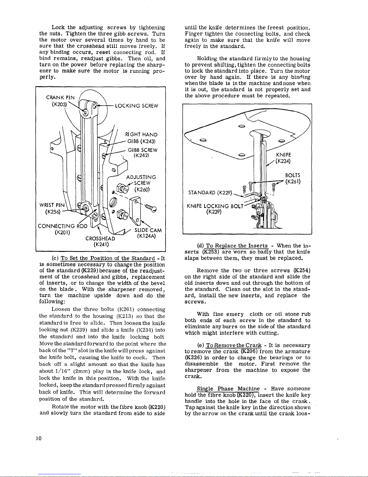
(c)
To
Set
the
Position
of
the
Standard
-It
is
sometimes
necessary
to
change
the
position
of
the
standard
(K229)
because
of
the
readjust-
ment
of
the
crosshead
and
gibbs,
replacement
of
inserts,
or
to
change
the
width of
the
bevel
on
the
blade
• With
the
sharpener
removed,
turn
the
machine
upside
down and do
the
following:
Loosen
the
three
bolts
(K261)
connecting
the
standard
to the
housing
(K213)
so
that
the
standard
is
free
to
slide.
Then
loosen
the
knife
locking
nut
(K239)
and
slide
a knife
(K234)
into
the
standard
and into the knife locking
bolt
Move
the
standard
forward
to
the
point
where
the
back
of
the
"T"
slot
in
the
knife will
press
against
the knife
bolt,
causing
the
knife to cock.
Then
back
off a
slight
amount
so
that
the
knife
has
about
1/16"
(2mm)
play
in
the
knife
lock,
and
lock
the
knife
in
this
position.
With
the
knife
locked,
keep
the
standard
pressed
firmly
against
back
of
knife.
This
will
determine
the
forward
position
of
the
standard.
Rotate
the
motor
with
the
fibre
knob (K220)
and
slowly
turn
the
standard
from
side
to
side
10
until
the knife
determines
the
freest
position.
Finger
tighten
the
connecting
bolts,
and
check
again
to
make
sure
that
the knife
will
move
freely
in
the
standard.
Holding
the
standard
firmly
to the housing
to
prevent
shifting,
tighten
the
connecting
bolts
to
lock
the
standard
into
place.
Turn
the
motor
over
by hand
again.
If
there
is
any bincling
when
the
blade
is
in the
machine
and none when
it
is
out,
the
standard
is
not
properly
set
and
the above
procedure
must
be
repeated.
KNIFE
LOCKING
BOLT
(K239)
BOLTS
~.....,_,..;..---:?"
(
K26
1)
(d)
To
Replace
the
Inserts
- When
the
in-
serts
(K253)
are
worn
so
badly
that
the
knife
slaps
between
them,
they
must
be
replaced.
Remove
the
two
or
three
screws
(K254)
on
the
right
side
of the
standard
and
slide
the
old
inserts
down
and
out
through
the
bottom
of
the
standard.
Clean
out
the
slot
in
the
stand-
ard,
install
the
new
inserts,
and
replace
the
screws.
With fine
emery
cloth
or
oil
stone
rub
both
ends
of
each
screw
in
the
standard
to
eliminate
any
burrs
on
the
side
of
the
standard
which
might
interfere
with
cutting.
(e)
To
Remove
the
Crank
-
It
is
necessary
to
remove
the
crank
(K206)
from
the
armature
(K226) in
order
to
change
the
bearings
or
to
disassemble
the
motor.
First
remove
the
sharpener
from
the
machine
to
expose
the
crank.

ens
on
the
armature.
The
crank
has a left-
hand
thread
and
must
be
turned
clockwise
to
be
re-
moved
from
the
armature.
3
Phase
Machine -The
crank
is
secured
by a stud
locked
against
the
armature
shaft.
The
stud
is
held
in
position
by a 1/4-20
set
screw.
Insert a 1/8"
Hex Key
into
set
screw
located
in
front
of
crank,
and
loosen
screw,
Remove
crank
as
described
above,
(f)
To
Replace
the
Motor
Bearings -The
motor
bearings
must
be
changed
if
the
motor
operates
noisily
without
the
crosshead
and
gibbs.
Back
motor
bearing
(K219) -
It
is
neces-
sary
first
to
remove
the
back
housing
(K222)
and
then
push
the
bearing
out.
Replace
the
back
housing
and
tighten
the
motor
bolts
(K224).
Then
put
in
the
new
back
bearing.
When
in-
stalling
a new
bearing,
place
the
old
bearing
behind
it
while
tapping
it
into
the
back
housing.
Rotate
the
old
bearing
when tapping
so
that
the
pressure
will
be
evenly
distributed.
In
this
way,
neither
the
inner
nor
the
outer
race
of
the
new
bearing
will
be
harmed.
Front
motor
bearing
(K246)
-Remove
the
armature
(K226)
after
removing
the
crank
and
back
housing.
Unscrew
the
bearing
lock
(K244)
and
then
(from
the
armature
side)
push
the
bearing
forward
and
out.
Install
the
new
bear-
ing
as
described
in
the
previous
paragraph.
(g)
To
Replace
Crank
Pin
Bearing -The
crank
pin
bearing
(K204)
must
be
changed
when
the
crank
pin
(K203)
is
loose
in
the
bearing
or
when
the
crank
pin
does
not
turn
smoothly
in
the
bearing.
Remove
the
bearing
lock
(K202)
on
the
face
of
the
crank,
remove
the
screw
in
the
back
of
the
crank,
and
tap
the
bearing
out
from
the
back.
(h)
To
Reassemble
Motor
- (Single
phase
Powrcrest
II only)
It
is
extremely
important
that
the
stator
(K216)
and
the
back
housing
(K222)
be
replaced
in
proper
position
on
the
front
housing
or
the
motor
itself
will
not
funcltion
properly.
The
stator
should
be
replaced
on
the
front
housing
so
that
the
model
name
or
"M"
in-
signia
on
both
sides
of
the
nameplate
are
in
the
same
horizontal
plane
The
Back
Housing
has a line
scribed
on
the
underside
which
matches a line
scribed
on
the
underside
of
the
Stator.
These
two
lines
must
be
in
line
with one
anotherwhen
the
Back
Hous-
ing
is
replaced
onto
the
Stator.
See
illustration
below.
UNDERSIDE
OF
HOUSING
11

12
ALWAYS GIVE MACHINE
SERIAL
NUMBER
WHEN ORDERING
PARTS
K3
~~
Kl
~
K21
K20
K16~
"';,
KlB
K6
K48
K33
""'
"'-._
"'-._
'1
I
I
I
r
~K34
'
I
~
I
I
~K36
I
Kl5 I
~
Kl5
1
K37
•
I . .
-.>.;;;:::
•.•
•.
K
-
ORDER
BY
PART
NUMBER
- NOT KEY
NUMBER

I"AKT:i
Ll:il
1
PART
PART
KEY
NO.
DESCRIPTION
KEY
NO.
DESCRIPTION
K1
802S Latch Spring Screw
K24
1245
Collar Washer, K Square Shaft
K2 802 Latch Spring
K25
813
Square Shaft Collar
K3
801
Latch
K26
1265 Spring
For
Presserfoot
Leg
Guide
K4
822S Screw For Bearing Block
Top
K27 1262
Pin
for
1265
Kfi.
811
Bearing Block
Top
K29
1254
Carrier Tube Bushing
K6 1229 K
Square Shaft (give
size)
K30
1255
Lock
Screw, Carrier Tube
K7
824
Presserfoot
Lift
K32
1258
Carrier Tube
K9 824U
Screw For K Presserfoot
Lift
K32A
1259
\'..'asner
For
Tube
K10
1171 K Presserfoot
Leg
(give
size)
K33
1275
K
Stone Carrier, Right
K11 1269
Pivot Screw For 1266
K34
1285
Gea'. Stone Carrier, 32 T
K12
1266 Presserfoot
Leg
Guide
K35
1276
K
S:one Carrier,
Left
K13
1291 Guide
For
Stone Carrier, Right
K36
1261
Snao
~
·r~
~=or
1276
K14
1328 Screw For Slide Guide K37 1277
S'la:::'
==\
·r2
;::Jr 1258
K15
1300 #60 K Stones w/Bushing, Pair
K38A
824T
Sc---=.··
::·
::::::k
sc:Jd
1468 & 1469
1301
#1
00 K Stones w/Bush ing, Pair
K40A
805P
9c
:::~"c:;c1280
1302
#150
K Stones w/Bushing, Pair
K41
1280
<
Sc:
....
~--~
SCi~~
~ear
K16
1296
Stud For Spring
K42
1279
'.',
::s~:;'
:::,
SJJ3'e
Shaft Gear
K17 1294
Spring, Right, For Guide 1291
K43
1475
C::--
...
~--
3 ::-:.
:.
1234
and
1255
K18
822S Screw For Carrier Block
K45
1329 s
==
·..:
.....
==
:.
0"
K19 1295 Spring, Left,
For
Guide 1290
K46
1464
~=:=--~~-~
K20
803N Trigger Stop
Nut
K47 1469
,::;,=-
s~
::":
-
:::'l;c
K21 803 Screw For Trigger Stop
K48
1465
,,, ~ =·
-=
....
s=
::;-=;3
...
K22
1200 K Slide (give size
and
stroke)
K49
1468
G~::
..
Sia;:. S .... o ..
t
K23
1290
Guide
For
Stone Carrier,
Left
K50
1466
•.• ~ ...
.::..,s.:=
..
~:=ear
ALWAYS
GIVE
MACHINE
SERIAL
NUMBER
WHE:'\
OR:!:::-·,::;
:::.:.,::ns.
ORDER
BY
PART
NUMBER-NOT
KEY
\,L;'.'3!:):;).
13

ALWAYS
GIVE
MACHINE
SERIAL
NUMBER
==::::..~~~WHEN
ORDERING PARTS
K122A
\
K1~~~.
3
L
Ki
114
A~
K!lS
K117A
~1Jr·
.
'fj'§J~~
Kll2
\-~
\.
~-@?
~
Klll
\.,.-I.'
-~-
-~
-·
"'"
'[)
"'---
-
--
- -
-l
-
_@;-..::::
1·~
~--
~t---l
I
--u.>-,
----
FK146AI
.
K143A
IKl
44
~
0
~
I
KllO
I
K145
)2))
_j
K146B
I
IK156
K146
~~\
I
I
K103A-IJ
K101
SQUEEZE
TRIGGER
ASSEMBLy
K186
~
K188 K187
~
~~~'
K189~
K183,---
r
K190
K191
K184
K182
K192 K193
K180
14

KEY
K1
01
K102
K103
K103A
K105
K106
K107
K108
K109
K110
K111
K112
K113
K113A
K114A
K115
K116
K117A
K120
K122A
K123
K124A
K124B
K129
K130
K131
K132
K133
K134
K135
K136A
K136B
K137
K138
K139
K139A
K140
K141
K142
K143A
PART
NO.
859C
822S
837
837R
1100
834R
835
836
836A
1125
840
840A
838C
840P
840D
1492
1156
836N
838B
1491
838N
1499
1187
1327
1328
802S
1325
856
816FS
858A
841B
842B
1164
1165
1165X
1160
843
1151
829B
836N
802S
831
1340
K144
516
K145
848C
K146 839
K146A
805P
K146B 839W
K147
830
*830A
K148A
1190
*1190B
PARTS
LIST 2
DESCRIPTION
Screw, Lower Right,
to
Fasten K
Sharpener
to
Machine
Screw For Upper Gear Block
Driver
Sprocket
Pin
K Frame (give size
and
stroke)
Chain Roller
ld ler Sprocket
Stud
For Idler Sprocket
Eccentric Stud (w/807W)
K Chain (give size and stroke)
Trigger For
Sharpener
Spring
For Sharpener Trigger
Bearing
For
Pulley
Support
(outer)
Trigger
Pin
Retaining Ring
Pulley Bracket w/Bushings
(for
1491 & 1497)
Safety Lock Screw
Safety
Lock
Nut
Bearing For Pulley
Support
(inner)
Shaft For Pulley
(with
1492 & 1497)
Nut
For Pulley
Slip Pulley
Sharpener
Anchor
Screw -
3/8"
Slide Cam,
nylon
Screw
For
Slide
Cam
Screw
For
Side Cover
K Side Cover
Presserfoot
Cam
Screw
For
Cam
Bracket
Cam
Bracket
Bushing For Bevel Gear
Bevel Gear 16
Shifter
Plate
Edge
Control
Arm
Edge
Control
Arm
w/887
Snap Ring
For
Pivot Stud
Gear
28/16
Mitre
Assembly
Spacer Rod
Stud
For
829
Gear
Nut
For
Idler Sprocket
Screw
For Cover Slide
Top
Cover Slide
Top
Rod
For
Pulley Bracket
(with
1158A)
Front
Bracket Screw, Upper
Spacer,
Front
Bracket
Gear 16 Teeth
Pin, Gear
Washer, Gear
Gear Assembly
50/12
Teeth
Gear Assembly
50/20
Teeth
Gear
28/12
T (large bore)
Gear
28/26T
(large bore)
KEY
PART
!\0.
K149A
1186
K150 829
K150A
K151
K152A
·329c
1481
828
1184
1184X
K152B 1188
K152C 1189
K152D 1192
K153
K154
K155A
K156
K157
K158
K159
K161
K162
K163
K164A
K164B
K165
K166
K167
K168
K169
K170A
K171
K172
K180
K181
K182
K183
K184
K185
K186
K187
K188
8483
410
1185
802S
864S
887
+8873
1191
492
489
1193X
1341
1158C
427
1159
870S
1194
856L
1158A
841.~
490
480.A
1256
480D
323PJ
481C
4813
480E
480E
481G
481E
481D
K189
490
K 190
481
F
K191
480F
480G
K192 480H
K193
481A
480X
DESCRIPTION
Retaining Ring
Gear Assembly
64/20
Teeth
Gear Assembly
56/20
Teeth
Retaining Ring
Sprocket Gear 32 Teeth
<
Front
Bracket
(for
edge
control
::rc-r
;, 1185, 1186
<
F•.Jnt
3racket
w/1185,
1186,
1122
..:,-~
:...oc"'
P n
So-~;.~-~
Lock
->~
:_:,:<
Se:
Screw
S:-:::
.. Lc :.er
Le"t
to
Fasten
S-c·:.:;-:;r
:::;
'.lachine
F-:-:
::-:::.::::: S::-e'.'.', Lower
:_:::·;
S:~::
F::- E·]ge Control
Arm
< ~ .::
S:
...
:
?-::;;::-.,::::::a~
Sroe
~:::;-
;:::;:,-:;
C•C'<
S:_::
=:·
:O::.e
Ge:or
8-.Jshing
:::::~
:.
:-
~S:JE
and
Pins
S:
.. ~ .·.
;
:>J.:;
3
Socket
Cap
S:·:::. ':-,::; 3 Socket
Cap
P-e::s::--Too:
Le'.
er
P-::sse-"'oo: Lever
with
490
Se-e:.
5 16x3 8 Set
Sere:. i
4x3
8 Shoulder
:::o
cr
·:,
ith
Screw
Cc
ar
;, ith 480H
and
481 A
Spr;ng
Sere.";
6x 1 8 Round Hd.
Sq..Jeeze
Trigger Assembly
with
480D
and
481
D
* For
Half
Speed
and
Cyclomatik
Machines
Only
ALWAYS
GIVE
MACHINE
SERIAL
NUMBER
WHEN
ORDERING
PARTS.
ORDER
BY
PART
NUMBER-NOT
KEY
NUMBER.
15

ALWAYS
GIVE
MACHINE
SERIAL
NUMBER
WHEN
ORDERING
PARTS
K211
__;r(
~
K210 U
K262~-~
~K263
~:
K209 I '
d.
I
~
"' '
~
l.,
1
K208:(
,,
K249 K
212
"--
K248
"
" K207 K247'-..
~~\'~
K245~
K244
K246~
K205 () K257
K206~~-\W
K204
K202 K203
~~
~
K243""
'1,
~~~
K242~~
K2411
~
,
____
D I
...---__.....-
1
11
K256
----~
ta
\',
___-
___-
K239
;f'O,
J
~
K240
c
K201
K215
K254
K239
_/>
~
'~(C))
! '
~
K255
~"i
_:®
I
K264
K232
I K230
~
K227
~K231
K228
K234
16
/
/
K223
/1
/
/
/
I
_)
K226
__-//
f
i__-~K224
r-------
-~
_ ... -
I
I
I
I
I
I
I
I
~..J
~~'
K290
K291
K289

PARTS
LIST
3
PART
PART
KEY NO.
DESCRIPTION
KEY
NO.
DESCRIPTION
1
3
1 3
PHASE
PHASE
PHASE
PHASE
K201
412A
412A
Connecting Rod ~ H
K241
411 411
Crosshead
with
Wrist Pin
412B
412B
Connecting Rod ~ M
K242
490A
490A
Screw
8x3/4
Fil. Hd.
412C 412C Connecting Rod ~ L
K243
409 409 Gibbs,
Pair
4120
4120
Connecting Rod ~
Ll
K244
404C 404C Bearing Lock
K202
413W 413W Bearing Lock
K245 867 867
Brake
K203 415
415
Crank
Pin
K246 403 403
Bearing #203
K204
414 414 Crank Bearing
K247
822S 822S Screw
6x1/4
Bind. Hd.
K205
415N 415N
Crank
Pin
Nut
K248 406
406A
Terminal
Pin
K206
413BX 413GX Crank
with
413W, 414,
415~
H
K249
405
405A
Terminal Block
with
Pins
413CX
413HX
Crank
with
413W,
414,415 ~ M
K250
441C 441C Cover, Switch
4130X
413JX Crank
with
413W,
414,415 ~ L
K251
441S 441S
Screw
6x5/16
Fil. Hd.
413EX
413KX
Crank
with
413W,
414,415 ~ Ll
K252 423 423 Handle Only
K207
866X 866X
Pulley Cover
with
Brake
423A 423A
Handle with Block
K208
867N
867N
Nut
423B 423B Handle, Upturned,
with
Block
K209
516
516
Screw,
8x5/16
Fil. Hd. 423E 423E
Handle Assembly Drilled
for
Oiler
K210
4070 4070
Top
Handle
K253
428A
428A
Insert
for
Standard ~ 9"
K211
408
408
Screw, 8x1-1/8 Flat Hd.
428B
428B Insert
for
Standard ~ 8"
K212
405F
405B
Fibre Cover
428C 428C
Insert
for
Standard~
7"
K213
402K
4020
Front Housing (Give Serial No.)
4280
4280
Insert
for
Standard ~ 6"
K214 400F
400F
Fan
(Give Serial No.)
428E
428E Insert
for
Standard ~ 5"
K215 400W
400W
Fan
Washer
(Give Serial No.)
428F 428F
Insert
for
Standard ~ 4"
K216
15000 15000 Field (Give Serial No.)
428H
428H Insert
for
Standard ~ 11"
Series
Series
428M 428M Insert
for
Standard ~ 14"
K217
421
Brush
Cap
K254
428S 428S Insert Screw
K218
420
Carbon Brush
K255
429
429 Baseplate
with
Rollers
and
Lip
K219 418
418 Bearing
#202
429A
429A Small Baseplate
with
Rollers
and
Lip
K220 422B
422M
Knob Assembly K256 411P 411P Wrist Pin
K221 422CB
422CB Knob Cover K257
409S 409S
Screw
8x3/8
Truss Hd.
K222
417C
4170
Back Housing (Give Serial No.) K258
402B
402B Oil Cup
Assembly
417CX
Back Housing Assembled
with
Brush K259
442 442B
Switch
Tubes, 2-421,
417L
(Give Serial No.)
K260 410 410 Screw
8x1/2
Fil. Hd.
K223
417L
Shunt Wire
410N 410N
Nut
#8
K224
419
419
Bolt
(Give Serial No.)
K261
425
425
Bolt
419N 419N
Nut
(Give Serial No.)
K262
458B
458A
Current Connector, Grounded
K225
400G
Short·Circuitor
(Give Serial No.)
K263
458K
458M Ground Shield
K226 15000 15000
Armature (Give Serial No.)
K264
457 457
Knife Key
Series
Series
K227
436
436 Roller Carrier Assembly
436A
436A
Roller Carrier
for
Small Baseplate
POWRTRON & POWRPAK
II
MOTORS
436B 436B Roller Carrier Cover
for
436A
K270
419Y
419Y
Bolt 8x4
K227A
436K
436K Rubber Cushion
419X
419E
Bolt, Powrpak II
436L
436L
Rubber Cushion
for
Small Baseplate
K271
402F 402G F rant Housing
K228
436S 436S
Screw,
Roller Carrier
K272
464A
464A
Tapered Handle
with
Block
K229
424A
424A
Standard ~ 9"
4648
464B
Tapered Handle
Only
424B 424B
Standard
~
8"
464F 464F
Tapered Handle Assembly
for
Oiler
424C
424C
Standard ~ 7"
K273
443
443A
Switch, Rocker
424D 424D
Standard
~
6"
K274
466 466
Switch Box Cover
424E 424E
Standard
~
5"
K275
818S 818S
Screw
6x1/4
Flat Hd.
424F
424F
Standard
~
4"
K276
400FB 400FB
Fan
XX
424H
424H
Standard
~
11"
K277
400FD
400FD
Fan
Washer
XX
424M 424M
Standard~
14"
K278
438W 438W
Washer
K230
430
430 Lip
K279
802S 802S
Screw
6x3j16
Bind. Hd.
430A
430A
Lip
for
Small Baseplate
K280
15080
15086
Field, Powrtron
K231
435
435
Cone
Lock
and
Nut
15105
15030
Field, Powrpak II
K232
426
426 Throat Plate
K281
15079 Capacitor
426B 426B
Throat Plate
~
9"
Standard
15078 Capacitor, Powrpak II
426V 426V
V-Throat Plate
with
427N
K282
15084
Cover,
Capacitor
427
427
Screw, 10x7/16 Flat Hd.
K283
1187
Screw
10x3/8
Fil. Hd.
427N
427N
Nest,
Brass
K284
15081 15085
Armature, Powrtron
K233
433A
433A
Spring,
Lip
15115 15027
Armature, Powrpak
II
433B
433B
Spring
for
Small Baseplate
K285
302L
302K
Back Housing, Powrtron
K234
Blade
(See
Next
Page)
K286
365
Relay
K235
802S 802S
Screw,
6x3/16
Bind. Hd. 365B
Relay, Powrpak II
K236
431A 431A
Shaft, Long
K287
441S · Screw 6x 5/16 Fil. Hd.
431B 431B
Shaft, Short
K288
403 403 Bearing
#203
K237
436S 436S
Screw,
Roller Carrier K289
4040 4040
Loading Spring
K238
802S 802S
Screw
6x3/16
Bind. Hd.
K290
422B
422M
Back Knob
K239 416 416
Knife
Bolt
and
Nut
K291
422E 422E Knob Cover
K240
411A
411A
T-Siot Lock
K292
434 434
Screw
6x3/16
Rnd. Hd.
ALWAYS
GIVE
MACHINE
SERIAL
NUMBER WHEN ORDERING PARTS.
ORDER BY PART
NUMBER-NOT
KEY
NUMBER.
17

::>ng
~flon
>w
Wave
>w
Wave
!d
:ed
lOS
Dozen
Each
Dozen
Each
Dozen
Each
Dozen
Each
Dozen
Each
Dozen
Each
Dozen
Each
Dozen
Each
Dozen
Each
Dozen
Each
Dozen
Each
Dozen
PART NUMBERS OF BLADES
AVAILABLE
BLADE SIZE
4"
5"
6"
7"
8"
30010
30011
30012 30013 30014
30040
30042 30044 30046 30048
30041
30043 30045 30047 30049
30080
30082 30084
30086
30088
30081
30083
30085 30087
30089
-
-
30100
-
30102
-
-
30101
-
30103
30110
30112 30114
30116
30118
30111
30113
30115
30117
30119
30130
30132 30134
30136 30138
30131
30133 30135
30137 30139
- 30152 30154
-
30158
-
30153 30155
-
30159
30170 30172 30174 30176
30178
30171
30173 30175
30177
30179
30210 30212 30214 30216
30218
30211
30213 30215
30217 30219
30230
-
30234
-
30238
30231
-
30235
-
30239
30250
30252 30254 30256 30258
30251 30253 30255 30257 30259
30340 30342 30344 30346
30348
30341 30343 30345
30347 30349
9"
11"
14"
30015
-
-
30050
-
-
30051
- -
30090 30092 30094
30091 30093
30095
30104
-
-
30105
-
-
-
-
-
- -
-
30140
-
-
30141
- -
- -
-
-
-
-
- -
-
- -
-
30220 30222
30222
30221
30223 30223
-
-
-
-
-
-
-
-
-
-
- -
30350 30352
30354
30351
30353 30355
Note
that there
is
a different part number for
single
blades
and
boxes of one dozen (12).
Please
order
by
part number.
H.
MAIMIN
CO.,
INC.
119 WEST 40th ST., NEW YORK, N.Y. 10018 U.S.A.
Printed in U.S.A.
 Loading...