

Maimin 59, 86, 87, 37 User Manual
BOOK NO.
22102
MAIMIN°
©1980
EDITION
H.
MAtMIN
CO.,
4
INC.
-ROUND
I.
DESCRIPTION
l
~
l.
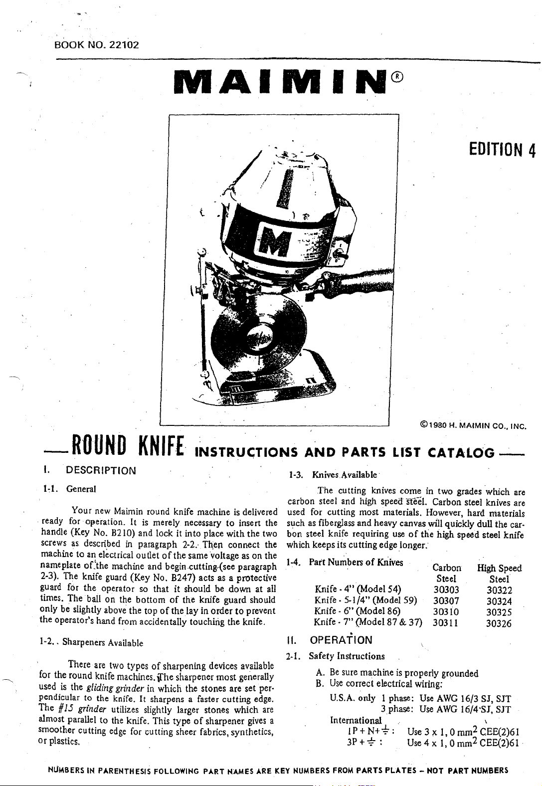
General
Your new Maimin round knife machine
ready for
handle (Key No.
screws
machine to
nameplate
2-3). The knife guard (Key No. B247) acts as a protective
guard for the operator so
times. The ball
only be slightly
the operator's hand from accidentally touching the knife.
1-2
..
' There are two types
for the round knife machines.
used
pendicular to the knife. It sharpens a faster cutting edge.
The
almost parallel
smoother cutting
or
plastics. .
O!}eration. It is merely necessary
as.
described
a!!
electrical outlet
oCthe machine
on
above the top
Sharpeners Available
is
the
gliding
#
15
grinder
to
KNIF£.
B2
10)
and lock it into place
in
paragraph
of
and
that
the
bottom
of
of
sharpening devices available
\[he
grinder
utilizes slightly larger stones which
the knife. This type
edge
in
which the stones are set per·
for cutting sheer fabrics, synthetics,
INSTRU<;TIONS
is
delivered
to
insert the
with
the two
2·2.·
Th;en connect the
the same ·voltage
begin cutting.-(see paragraph
it
should be down at all
of
the knife guard should
the lay in
sharpener
order
of
sharpener
most
as
to
prevent
generally
gives
on
are
AND
1·3.
carbon steel and high
used for cutting most materials. However, hard materials
such as fiberglass and heavy canvas
bon steel knife requiring use
which keeps
the
1-4.
Part Numbers
PARTS
Knives
Available·
The
cutting knives come in two grades which are
its cutting edge longer.
Knife · 4" (Model 54)
Knife·
5-1/4" (Model 59)
Knife
·
6"
(Model 86)
Knife·
7"
(Model87
of
LIST
speed·
Kriives
CATALOG-
ste-eL
Carbon steel knives are
will
of
the
high speed steel knife
Carbon
Steel
30303
30307
30310
& 37)
30311
quickly dull the car-
II. OPERATION
2-1. Safety Instructions
A.
Be
sure machine
B.
Use
correct electrical wiring:
U.S.A. only 1 phase:
a
International
IP+N+-4:-:
3P+-;:-:
is
properly grounded
Use
3phase:
Use
.·
Use3;x
Use4x
AWG
16/3 SJ, SJT
AWG
l6/4·SJ,
l,Omm2CEE(2)61
l,Omm2CEE(2)61
High Speed
Steel
303.22
30324
30325
30326
SJT
'
NUMBERS
IH PARENTHESIS FOLLOWING PART HAMES
ARE
KEY NUMBERS
FROM
PARTS
PLATES-
HOT PART NUMBERS
C.
Keep cutting area clean and well lit.
D.
Keep visitors away from
E.
Do
not
use machine in
F.
Store machine
G. Keep machine clean
safest performance.
H.
Always disconnect machine
fore servicing, and when changing blade.
in
dty
and
I. Remove knife key from knife
ing motor.
J.
·:se
sure switch
cord.
K.
Disconnect electrical cord before carrying
macrune.
L.
Keep knife guard in place and
blade.
2-2.
To
Attach Handle
Insert the metal stud
into its
the handle screw
· into the standard, and tighten
position with the handle lock screw
on
2-3.
(B41). Flip switch
2-4.
raise knife guard
should
tor safety. When
knife guard to the roller plate.
bole
the side
To
Start
Attach
To
Cut
Loosen
only
in
the upper rear
(8211)
or"
the standard. ·
current connector
(847)
the
(8247)
be
slightly above
the
is
off
before connecting electrical
of
ofthe
through
it.
to
"on,
guard
carrier screw (B248) slightly and
to
hdght
the
machine is
cutting
damp
location.
blade sharp for best and
the
handle
the
Then
(8214)
(840)
position.
oflay
top
not
area.
or
wet
location.
·
when
not
in use, be-
lock
before start·
hands
away from .
(Key
No.
standard
flange
lock
to
of
being used, lower the
(8216).
of
the
the handle into
and
nut
the
terminal pins
.·The
knife guard
the lay for
8210)
Put
handle
(B213)
opera•
3-2.
To
Lubricate
Grease
by
turning
ard one complete turn. When the grease
screw it,
used
is
thus
require
3-3. To
. After repeated use, the ·sharpening stones (B2S9)
become coated with grease
knife effectively.
Stone Cleaner directly
cleaning fluid
The
dirt
not
be
run
inflammable cleaning fluid.
3-4.
To
a) Gliding Grinder (Plate
(8254).
stone
in the grinder frame
.screw, and
frame.
washer
slide the neck
ing sure
neck
slot. Then
washer
is
Unscrew
with
Be
(8255).
that
of
the
and
explained in paragraph
the
gear
(8239)
the
grease
cup
fill
it with grease and replace.
Lubriko M32.
no
lubrication. ·
Clean
Stones
on
will
be
near ll18terial
CbangeStones
First remove knife. Loosen stone Jock $crew
bushing
pun
the stone with bushing
careful
When installing the new stone with bushing,
of
the
stone
the
stone lock
screwed iilto
The
To
remove this coating, spray Maimin
a toothbrush
flung off; therefore, the sharpener should
the
stone adjusting screw
(8259)
(B2S8), Then remove the stone lock
not
to
lose
the
stone bushing into
coil spring
bushing and the stud
scr.ew
the
4-la.
and pinion
(8215)
onto
to
slides
on
motor
bearings are sealed and
and
dirt
a~d
the stones
to
scrub
avoid staining.
3)
out
the coil spring
is
in its position between the
should be fitted 'through the
stone bushing.
(B202)
the side
cup
The
do
not
or
the
stones. Sharpen.
(8257)
to
the
end
out
of
(8256)
the
slot, first mak-.
on
the
inside
The
is
Do
.,
monthly
of
the stand-
empty
grease
t~
sharpen the
put
a little
not
use
until the
of
the slot
the grinder
and the .
of
the
adjustment
un- <
be
· 2·5.
To
Sharpen Knife
With motor ruMing; firmly depress
trigger (B204) until
knife.
When sharpening the knife with
is
important that a light
used
on
the. trigger
ened bevel
Ill.
3-l.
NUMBERS
on
the
CARE & MAINTENANCE
Maintenance Schedule
Monthly:
Grease gear (paragraph
Clean sharpening
Clean motor(paragraph 3-8)
Six Months:
Every
Clean rollers (paragraph 3-9)
IH
both emery stones
but
constant fmger pressure be slightly and swung down.
to
maintain
kriife. interchange these
PARENTHESIS
the
same width
3·2)
stones (paragraph 3-3)
FOLLOWING
turn
the
PART
the
grinder ·
against the · Loosen
#15
grinder, it • remove the
of
sharp- frame arches completely
· and the entire assembly
HAMES
ARE
KEY
b)
#15
Grinder (Plate
the
top.
two. The frame arch .can then
bushings
adjusting bushings
bushings are removed from the end
the two
shaft. When putting
sure that
tween the
ings are then
frame
adjusting bushings
screws until
in
(8345)
(f
15 grinder stones with bushings are slid
the
(8347).
paragraph 4·1
NUMBERS
two
can then
(8339)
on
stone shaft spring
two
stones with bushings.
put
into
The frame arches are fitted properly over the
but
the
sharpener stones are adjusted as described·:
b.
FROM
PARTS
4)
four frame arch screws {8346) and
It
is
possible to· remove the
but
care should be t3ken
arches. The #15 grinder stones with
be
lifted
and the stone shaft {8344). The
new stones with bushings, make
(8343)
place behind the sharpening stones,
is
put
back
are
not
locked into place with the. ·
PLATES-
be
out
together with the
of
the shaft, and then
is
on
the shaft be-
Th~
adjusting bush-
on
the
·11
HOT
PART
NUMBERS·
pulled
out
two
not
to
off
the
s grinder
..,.
3-5.
To
Change
Detach
lower knife guard
Loosen
plate (8223) forward. Lift check spring (B260)
grinder frame
.grinder track
install knife. Remove knife
coumer·clockwise viith the knife key.
driver
damage
knife key handle towards the handle
move the knife key handle downward sharply,
against
sary
point the knife key handle towards the knife guard and
move the knife key handle downward sharply against the
roller plate
b~vel.
hole, must
the
wipe the
the two
or
the
If
the
the
to
loosen. the knife lock. To tighten the knife
A knife must be installed with its trademark
facing outward. The knif.e, with its specially shaped
gear; and the knife must·lie fiat against
knife clean before fitting
Knife
current
(8258),
(B220)
a punch to remove
knife lock and the gear bearing.
knife'lock does
r\)ller plate (8224). Repeat this action
lip
(B237).
be.fitted
connector (B40) from machine and
(B247).
throat
over the similarly shaped shoulder on
Lay
the machine on its side.
plate screws
and pull
for
sufficient clearance to remove
<!3232),
the
frame to the end
lock
(8245) by turning
Do
the
knife lock
not
readily unscrew,
of
it
onto
and slide
not
the
machine and
the
gear. Always
the
machine.
throat
on
top
use
a screw-
as
they will
point
striking it
if
neces-
l{)<:k,
and
3-6. To Remove Gear (8239)
First remove the knife
3-5. Unscrew gear cap
Then reinove gear screw
has a left-hand thread).
Take
off
the
grease
screws (8222). Lift
IMPORT ANT: When the spiral gear was
trunnion shaft. a few trunnion washers
the
behind
mesh
may
Do not lose these trunnion washers.
them on
any length.
the trunnion washers will not slip off.
3-7. To Clean
(8258) with compressed air. Check
freely. With a
so
that the grinder fnime will slide easily
3-8. To Clean
gear
of
the
gear
cause these trunnion washers to stick to the bearing.
the
tfunnion shaft.
of
time,
Sh~pener
Blow the lint and dust
clean cloth wipe
Motor
(8246)
Uft
ckculator.(B22!)
out
the
on
the trunnion shaft to create the
and·
the pinion. The greaSe on
put
the
as
described
by
turning counterclockwise.
(8244.)
by
thread seal
turning clockwise
by
gear with bearing.
Be
If
the
g.ear
is
gear screw back in place so
off
the grinder assembly
that
offthe
grinder track (B220)
in
paragraph
(8242)
off
removing its two
mounted
(8238)
on
were placed
certain
to be reriwved for
to
the
stones rotate
it.
the gear.
on
proper
the·
gear
replace
that
running, point a stream
the
motor
the
fan
to
eject
3·9. To Clean Rollers
of
of
or
it
rtot
Do
If
the
roll freely, blow
not
oil
lise a powdered
IV. ADJUSTMENTS & REPAIRS.
the.
4-1. To Adjust
a) Gliding Grinder (Pl'ate 3)
Unscrew
and then move the stones
turning
.stone lock
against
the
the trigger
knife should.
knife
moved closer
further away from
the stones are adjusted
screws .
(it
ing
from
at approximately
is
equal
the
.in
the frame arch
4-::!.
towards
knife and
I
/16"
throat plate slot. Adjust
two
roller plate
Press in the
spring (B236). When
tion,
teeth on the lip
the
stone
the
knife
(B104) is pulled slo.wly. The ground bevel
,..
approximately
b) # 15
Loosen
bushing (B339) to move.
the
knife. The
pulled slowly.
on
11oth
width. When the stones are .adjus.ted correctly, tighten
To Adjust
. As
the
the
·knife so
the
(
I.6mm).
throat
plate screws (B232) which are underneath the
(8224).
throat
release
of
compressed air into the
and
then
in
the
side
of
the
the
dust
and
lint.
rollers (8230) in. the roller plate
out
the
dust
or
as
it
will
collect .dirt causing the rollers
graphite
Sharpener
adjusting screw
screw.
at
be
ab~ut
together
yrinder
frame
the
The
sides and should be
screws
Throat
knife wears, move
front
The
plate lock (8235)
the
throat
spring. Tighten
for
lubrication
the
stone
to
Both
stones should begin revolving
approximately
the same
1/16;?
to
obtain
the
knife
to
properly,
(Plate
4)
arch
screws (B346).
the·
stones
should
same
time
ground
to
that
of
knife
the
bevel
lock
the
Plate
the
space between the edge
the slot
of
should
the
throat
throat
plate lock
the
lock· screw {8254)' one turn
or
away from the knife by
(8257).
the same
width
on
(
i.6mm).
a narrower bevel and
obtain a wider bevel. After
tighten the stone lock
stones towards
rotate
when the grinder trigger
on
the knife should be
about
stonedn
the
throat
the
throat
be
in
the middle
plate
to
slide it along the
plate
is
in the desired posi·
to
catch between the
throat
plate screws.
top
bottom
housing
(B224)
dirt in
if
against the knife
position.
by
the
rollers.
to
bind.
necessary.
Then
tighten the
moment
both
The stones are
Turn
3/32"
plate
plate
loosening the
on
sides
of
adjust·
or
away
(2.4mm)
(8223)
of
is
about
of
when
the
the
lip
of
by
do
the
the
Over a period
side the
motor
NUMBERS
IN
of
time, dust and lint will build up in· ·
and prevent proper cooling. With the
PARENTHESIS FOLLOWING
PART
NAMES ARE KEY NUMBERS FROM PARTS
motor
PLATES-
(continued
HOT PART NUMBERS
on back
corer}
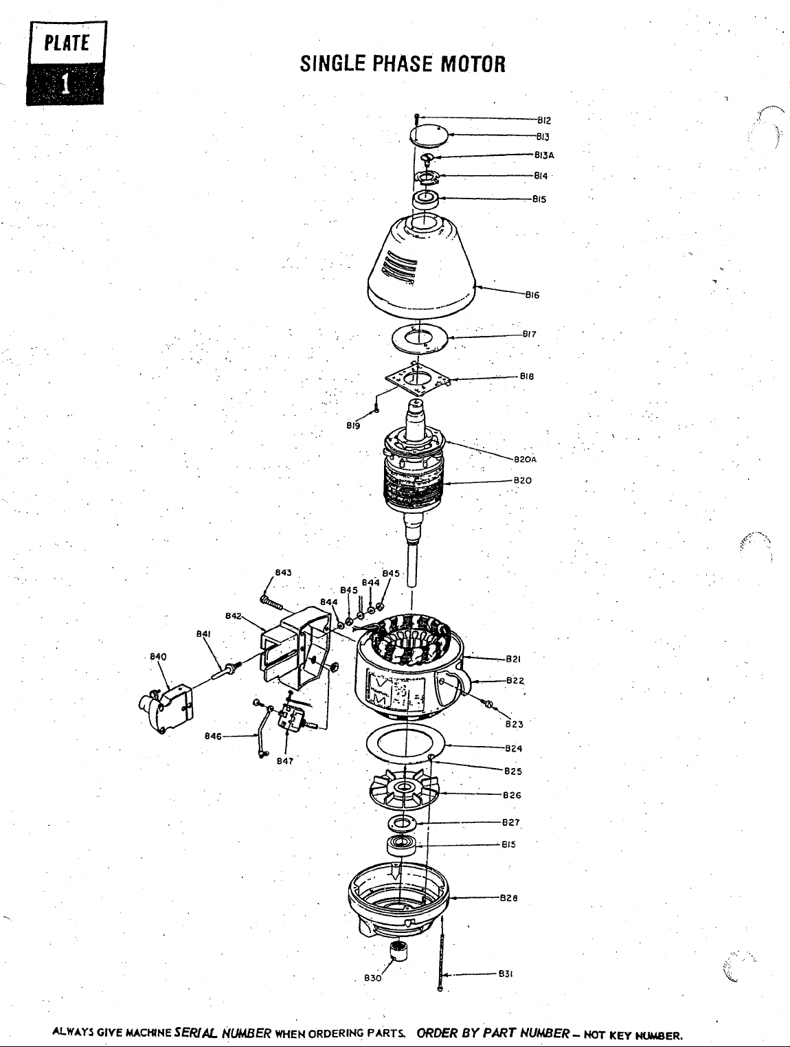
PlAT£
SINGLE
PHASE
MOTOR
-i~
·'·
842
84:5 .
t""'N~---.
~~-t----~815
--827
8:50
ALWAYS
GIVE
MACttNE
SERIAL
NUMBER
WHEN
ORDERING
PARTS.
ORDER
BY
PART NUMBER-
HOT
KEY
HUMBER.
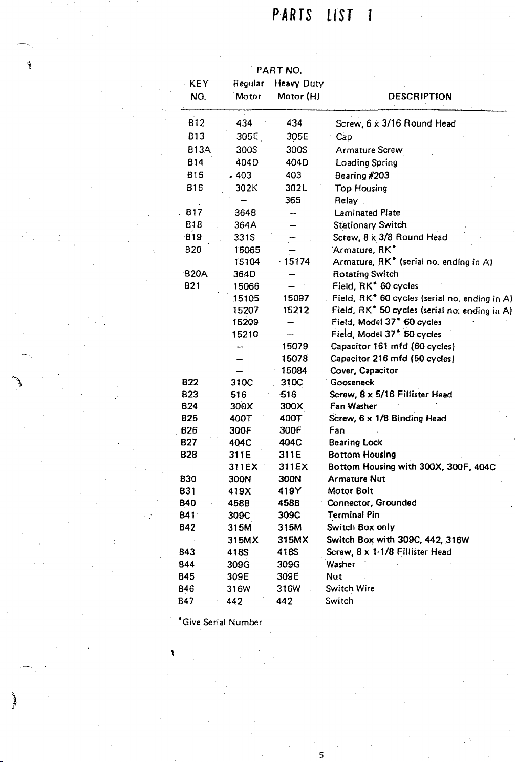
PARTS
LIST
1
'\
~
·~
PART
KEY
NO.
812
813
813A
814
815 • 403 403
816
817
818
819
820
B20A
821
B22
B23
B24
B25
826
827
828
B30
B31
B40
841
842
843
844
845
846
847
R~ular
Motor
434 434
305E 305E
300S·
4040 4040
302K
3648 Laminated Plate
364A
331S
15065
15104
3640
15066
.15105
15207
15209
15210
310C 310C
516
300X
400T
300F
404C
311E
311EX
300N
419X
458B
309C
315M
315MX 315MX
4185
309G
309E
316W
442
Heavy
Motor
419Y
4588
309C
315M
418S
309G
309E
316W
442
NO.
Duty
(H)
Screw, 6 x
Cap
300S
302L
365 Relay
. 15174
15~7
15212 Field,
15079
15078
15084
516
300X
400T
300F
404C
311E
311EX
300N
Armature Screw
Loading Spring
Bearing #203
Top Housing
Stationary
Sctew, 8 x
Armature,
Armature, RK
Rotating Switch
Field,
Field,
Field,
Field,
Capacitor
Capacitor 216
Cover, Capacitor
·Gooseneck
Screw, 8 x 5/16 Fillister
Fan
SCrew,
Fan
Bearing Lock
Bottom
Bottom
Armature
Motor
Connector, Grounded
Terminal Pin
Switch Box only
Switch Box
Screw, 8 x
Washer
Nut
Switch Wire
Switch
DESCRIPTION
3/16
Switch
3/8
RK"
• (serial no. ending in
HK"
60 cycles
RK"
60 cycles (serial no. ending in
RK"
50 cycles (serial no; ending in A)
Model
37"
Model
37"
161
mfd
mfd
Washer
6 x 1/8 Binding
Housing
Housing
Nut
Bolt
with
1-1/8 Fillister Head
Round
Round
60
5o
with
309C, 442, 316W
Head
Head
cycles
cydes
(60 cycles)
(50 cycles)
Head
Head
300X, 300F, 404C
Al
AI
"Give
Serial Number
)
1
5
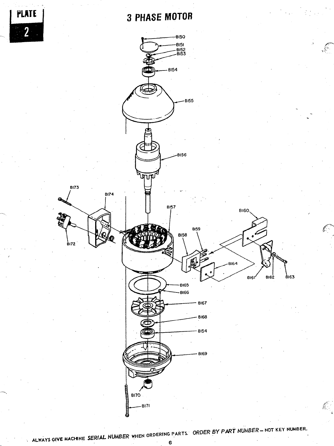
3
PHASE
MOTOR
ALWAYS
GIVE
MACHINE
SERIAL
NUMBER
WHEN
ORDERING
PART!..
6
ORDER
BY P /JRT
NUMBER-
HOT
KEY
HUMBER.
 Loading...