

BOOK NO.
22102
MAIMIN°
©1980
EDITION
H.
MAtMIN
CO.,
4
INC.
-ROUND
I.
DESCRIPTION
l
~
l.
General
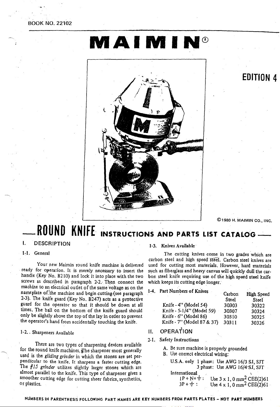
Your new Maimin round knife machine
ready for
handle (Key No.
screws
machine to
nameplate
2-3). The knife guard (Key No. B247) acts as a protective
guard for the operator so
times. The ball
only be slightly
the operator's hand from accidentally touching the knife.
1-2
..
' There are two types
for the round knife machines.
used
pendicular to the knife. It sharpens a faster cutting edge.
The
almost parallel
smoother cutting
or
plastics. .
O!}eration. It is merely necessary
as.
described
a!!
electrical outlet
oCthe machine
on
above the top
Sharpeners Available
is
the
gliding
#
15
grinder
to
KNIF£.
B2
10)
and lock it into place
in
paragraph
of
and
that
the
bottom
of
of
sharpening devices available
\[he
grinder
utilizes slightly larger stones which
the knife. This type
edge
in
which the stones are set per·
for cutting sheer fabrics, synthetics,
INSTRU<;TIONS
is
delivered
to
insert the
with
the two
2·2.·
Th;en connect the
the same ·voltage
begin cutting.-(see paragraph
it
should be down at all
of
the knife guard should
the lay in
sharpener
order
of
sharpener
most
as
to
prevent
generally
gives
on
are
AND
1·3.
carbon steel and high
used for cutting most materials. However, hard materials
such as fiberglass and heavy canvas
bon steel knife requiring use
which keeps
the
1-4.
Part Numbers
PARTS
Knives
Available·
The
cutting knives come in two grades which are
its cutting edge longer.
Knife · 4" (Model 54)
Knife·
5-1/4" (Model 59)
Knife
·
6"
(Model 86)
Knife·
7"
(Model87
of
LIST
speed·
Kriives
CATALOG-
ste-eL
Carbon steel knives are
will
of
the
high speed steel knife
Carbon
Steel
30303
30307
30310
& 37)
30311
quickly dull the car-
II. OPERATION
2-1. Safety Instructions
A.
Be
sure machine
B.
Use
correct electrical wiring:
U.S.A. only 1 phase:
a
International
IP+N+-4:-:
3P+-;:-:
is
properly grounded
Use
3phase:
Use
.·
Use3;x
Use4x
AWG
16/3 SJ, SJT
AWG
l6/4·SJ,
l,Omm2CEE(2)61
l,Omm2CEE(2)61
High Speed
Steel
303.22
30324
30325
30326
SJT
'
NUMBERS
IH PARENTHESIS FOLLOWING PART HAMES
ARE
KEY NUMBERS
FROM
PARTS
PLATES-
HOT PART NUMBERS
C.
Keep cutting area clean and well lit.
D.
Keep visitors away from
E.
Do
not
use machine in
F.
Store machine
G. Keep machine clean
safest performance.
H.
Always disconnect machine
fore servicing, and when changing blade.
in
dty
and
I. Remove knife key from knife
ing motor.
J.
·:se
sure switch
cord.
K.
Disconnect electrical cord before carrying
macrune.
L.
Keep knife guard in place and
blade.
2-2.
To
Attach Handle
Insert the metal stud
into its
the handle screw
· into the standard, and tighten
position with the handle lock screw
on
2-3.
(B41). Flip switch
2-4.
raise knife guard
should
tor safety. When
knife guard to the roller plate.
bole
the side
To
Start
Attach
To
Cut
Loosen
only
in
the upper rear
(8211)
or"
the standard. ·
current connector
(847)
the
(8247)
be
slightly above
the
is
off
before connecting electrical
of
ofthe
through
it.
to
"on,
guard
carrier screw (B248) slightly and
to
hdght
the
machine is
cutting
damp
location.
blade sharp for best and
the
handle
the
Then
(8214)
(840)
position.
oflay
top
not
area.
or
wet
location.
·
when
not
in use, be-
lock
before start·
hands
away from .
(Key
No.
standard
flange
lock
to
of
being used, lower the
(8216).
of
the
the handle into
and
nut
the
terminal pins
.·The
knife guard
the lay for
8210)
Put
handle
(B213)
opera•
3-2.
To
Lubricate
Grease
by
turning
ard one complete turn. When the grease
screw it,
used
is
thus
require
3-3. To
. After repeated use, the ·sharpening stones (B2S9)
become coated with grease
knife effectively.
Stone Cleaner directly
cleaning fluid
The
dirt
not
be
run
inflammable cleaning fluid.
3-4.
To
a) Gliding Grinder (Plate
(8254).
stone
in the grinder frame
.screw, and
frame.
washer
slide the neck
ing sure
neck
slot. Then
washer
is
Unscrew
with
Be
(8255).
that
of
the
and
explained in paragraph
the
gear
(8239)
the
grease
cup
fill
it with grease and replace.
Lubriko M32.
no
lubrication. ·
Clean
Stones
on
will
be
near ll18terial
CbangeStones
First remove knife. Loosen stone Jock $crew
bushing
pun
the stone with bushing
careful
When installing the new stone with bushing,
of
the
stone
the
stone lock
screwed iilto
The
To
remove this coating, spray Maimin
a toothbrush
flung off; therefore, the sharpener should
the
stone adjusting screw
(8259)
(B2S8), Then remove the stone lock
not
to
lose
the
stone bushing into
coil spring
bushing and the stud
scr.ew
the
4-la.
and pinion
(8215)
onto
to
slides
on
motor
bearings are sealed and
and
dirt
a~d
the stones
to
scrub
avoid staining.
3)
out
the coil spring
is
in its position between the
should be fitted 'through the
stone bushing.
(B202)
the side
cup
The
do
not
or
the
stones. Sharpen.
(8257)
to
the
end
out
of
(8256)
the
slot, first mak-.
on
the
inside
The
is
Do
.,
monthly
of
the stand-
empty
grease
t~
sharpen the
put
a little
not
use
until the
of
the slot
the grinder
and the .
of
the
adjustment
un- <
be
· 2·5.
To
Sharpen Knife
With motor ruMing; firmly depress
trigger (B204) until
knife.
When sharpening the knife with
is
important that a light
used
on
the. trigger
ened bevel
Ill.
3-l.
NUMBERS
on
the
CARE & MAINTENANCE
Maintenance Schedule
Monthly:
Grease gear (paragraph
Clean sharpening
Clean motor(paragraph 3-8)
Six Months:
Every
Clean rollers (paragraph 3-9)
IH
both emery stones
but
constant fmger pressure be slightly and swung down.
to
maintain
kriife. interchange these
PARENTHESIS
the
same width
3·2)
stones (paragraph 3-3)
FOLLOWING
turn
the
PART
the
grinder ·
against the · Loosen
#15
grinder, it • remove the
of
sharp- frame arches completely
· and the entire assembly
HAMES
ARE
KEY
b)
#15
Grinder (Plate
the
top.
two. The frame arch .can then
bushings
adjusting bushings
bushings are removed from the end
the two
shaft. When putting
sure that
tween the
ings are then
frame
adjusting bushings
screws until
in
(8345)
(f
15 grinder stones with bushings are slid
the
(8347).
paragraph 4·1
NUMBERS
two
can then
(8339)
on
stone shaft spring
two
stones with bushings.
put
into
The frame arches are fitted properly over the
but
the
sharpener stones are adjusted as described·:
b.
FROM
PARTS
4)
four frame arch screws {8346) and
It
is
possible to· remove the
but
care should be t3ken
arches. The #15 grinder stones with
be
lifted
and the stone shaft {8344). The
new stones with bushings, make
(8343)
place behind the sharpening stones,
is
put
back
are
not
locked into place with the. ·
PLATES-
be
out
together with the
of
the shaft, and then
is
on
the shaft be-
Th~
adjusting bush-
on
the
·11
HOT
PART
NUMBERS·
pulled
out
two
not
to
off
the
s grinder
..,.
3-5.
To
Change
Detach
lower knife guard
Loosen
plate (8223) forward. Lift check spring (B260)
grinder frame
.grinder track
install knife. Remove knife
coumer·clockwise viith the knife key.
driver
damage
knife key handle towards the handle
move the knife key handle downward sharply,
against
sary
point the knife key handle towards the knife guard and
move the knife key handle downward sharply against the
roller plate
b~vel.
hole, must
the
wipe the
the two
or
the
If
the
the
to
loosen. the knife lock. To tighten the knife
A knife must be installed with its trademark
facing outward. The knif.e, with its specially shaped
gear; and the knife must·lie fiat against
knife clean before fitting
Knife
current
(8258),
(B220)
a punch to remove
knife lock and the gear bearing.
knife'lock does
r\)ller plate (8224). Repeat this action
lip
(B237).
be.fitted
connector (B40) from machine and
(B247).
throat
over the similarly shaped shoulder on
Lay
the machine on its side.
plate screws
and pull
for
sufficient clearance to remove
<!3232),
the
frame to the end
lock
(8245) by turning
Do
the
knife lock
not
readily unscrew,
of
it
onto
and slide
not
the
machine and
the
gear. Always
the
machine.
throat
on
top
use
a screw-
as
they will
point
striking it
if
neces-
l{)<:k,
and
3-6. To Remove Gear (8239)
First remove the knife
3-5. Unscrew gear cap
Then reinove gear screw
has a left-hand thread).
Take
off
the
grease
screws (8222). Lift
IMPORT ANT: When the spiral gear was
trunnion shaft. a few trunnion washers
the
behind
mesh
may
Do not lose these trunnion washers.
them on
any length.
the trunnion washers will not slip off.
3-7. To Clean
(8258) with compressed air. Check
freely. With a
so
that the grinder fnime will slide easily
3-8. To Clean
gear
of
the
gear
cause these trunnion washers to stick to the bearing.
the
tfunnion shaft.
of
time,
Sh~pener
Blow the lint and dust
clean cloth wipe
Motor
(8246)
Uft
ckculator.(B22!)
out
the
on
the trunnion shaft to create the
and·
the pinion. The greaSe on
put
the
as
described
by
turning counterclockwise.
(8244.)
by
thread seal
turning clockwise
by
gear with bearing.
Be
If
the
g.ear
is
gear screw back in place so
off
the grinder assembly
that
offthe
grinder track (B220)
in
paragraph
(8242)
off
removing its two
mounted
(8238)
on
were placed
certain
to be reriwved for
to
the
stones rotate
it.
the gear.
on
proper
the·
gear
replace
that
running, point a stream
the
motor
the
fan
to
eject
3·9. To Clean Rollers
of
of
or
it
rtot
Do
If
the
roll freely, blow
not
oil
lise a powdered
IV. ADJUSTMENTS & REPAIRS.
the.
4-1. To Adjust
a) Gliding Grinder (Pl'ate 3)
Unscrew
and then move the stones
turning
.stone lock
against
the
the trigger
knife should.
knife
moved closer
further away from
the stones are adjusted
screws .
(it
ing
from
at approximately
is
equal
the
.in
the frame arch
4-::!.
towards
knife and
I
/16"
throat plate slot. Adjust
two
roller plate
Press in the
spring (B236). When
tion,
teeth on the lip
the
stone
the
knife
(B104) is pulled slo.wly. The ground bevel
,..
approximately
b) # 15
Loosen
bushing (B339) to move.
the
knife. The
pulled slowly.
on
11oth
width. When the stones are .adjus.ted correctly, tighten
To Adjust
. As
the
the
·knife so
the
(
I.6mm).
throat
plate screws (B232) which are underneath the
(8224).
throat
release
of
compressed air into the
and
then
in
the
side
of
the
the
dust
and
lint.
rollers (8230) in. the roller plate
out
the
dust
or
as
it
will
collect .dirt causing the rollers
graphite
Sharpener
adjusting screw
screw.
at
be
ab~ut
together
yrinder
frame
the
The
sides and should be
screws
Throat
knife wears, move
front
The
plate lock (8235)
the
throat
spring. Tighten
for
lubrication
the
stone
to
Both
stones should begin revolving
approximately
the same
1/16;?
to
obtain
the
knife
to
properly,
(Plate
4)
arch
screws (B346).
the·
stones
should
same
time
ground
to
that
of
knife
the
bevel
lock
the
Plate
the
space between the edge
the slot
of
should
the
throat
throat
plate lock
the
lock· screw {8254)' one turn
or
away from the knife by
(8257).
the same
width
on
(
i.6mm).
a narrower bevel and
obtain a wider bevel. After
tighten the stone lock
stones towards
rotate
when the grinder trigger
on
the knife should be
about
stonedn
the
throat
the
throat
be
in
the middle
plate
to
slide it along the
plate
is
in the desired posi·
to
catch between the
throat
plate screws.
top
bottom
housing
(B224)
dirt in
if
against the knife
position.
by
the
rollers.
to
bind.
necessary.
Then
tighten the
moment
both
The stones are
Turn
3/32"
plate
plate
loosening the
on
sides
of
adjust·
or
away
(2.4mm)
(8223)
of
is
about
of
when
the
the
lip
of
by
do
the
the
Over a period
side the
motor
NUMBERS
IN
of
time, dust and lint will build up in· ·
and prevent proper cooling. With the
PARENTHESIS FOLLOWING
PART
NAMES ARE KEY NUMBERS FROM PARTS
motor
PLATES-
(continued
HOT PART NUMBERS
on back
corer}
PlAT£
SINGLE
PHASE
MOTOR
-i~
·'·
842
84:5 .
t""'N~---.
~~-t----~815
--827
8:50
ALWAYS
GIVE
MACttNE
SERIAL
NUMBER
WHEN
ORDERING
PARTS.
ORDER
BY
PART NUMBER-
HOT
KEY
HUMBER.
PARTS
LIST
1
'\
~
·~
PART
KEY
NO.
812
813
813A
814
815 • 403 403
816
817
818
819
820
B20A
821
B22
B23
B24
B25
826
827
828
B30
B31
B40
841
842
843
844
845
846
847
R~ular
Motor
434 434
305E 305E
300S·
4040 4040
302K
3648 Laminated Plate
364A
331S
15065
15104
3640
15066
.15105
15207
15209
15210
310C 310C
516
300X
400T
300F
404C
311E
311EX
300N
419X
458B
309C
315M
315MX 315MX
4185
309G
309E
316W
442
Heavy
Motor
419Y
4588
309C
315M
418S
309G
309E
316W
442
NO.
Duty
(H)
Screw, 6 x
Cap
300S
302L
365 Relay
. 15174
15~7
15212 Field,
15079
15078
15084
516
300X
400T
300F
404C
311E
311EX
300N
Armature Screw
Loading Spring
Bearing #203
Top Housing
Stationary
Sctew, 8 x
Armature,
Armature, RK
Rotating Switch
Field,
Field,
Field,
Field,
Capacitor
Capacitor 216
Cover, Capacitor
·Gooseneck
Screw, 8 x 5/16 Fillister
Fan
SCrew,
Fan
Bearing Lock
Bottom
Bottom
Armature
Motor
Connector, Grounded
Terminal Pin
Switch Box only
Switch Box
Screw, 8 x
Washer
Nut
Switch Wire
Switch
DESCRIPTION
3/16
Switch
3/8
RK"
• (serial no. ending in
HK"
60 cycles
RK"
60 cycles (serial no. ending in
RK"
50 cycles (serial no; ending in A)
Model
37"
Model
37"
161
mfd
mfd
Washer
6 x 1/8 Binding
Housing
Housing
Nut
Bolt
with
1-1/8 Fillister Head
Round
Round
60
5o
with
309C, 442, 316W
Head
Head
cycles
cydes
(60 cycles)
(50 cycles)
Head
Head
300X, 300F, 404C
Al
AI
"Give
Serial Number
)
1
5
3
PHASE
MOTOR
ALWAYS
GIVE
MACHINE
SERIAL
NUMBER
WHEN
ORDERING
PART!..
6
ORDER
BY P /JRT
NUMBER-
HOT
KEY
HUMBER.

PARTS
LIST
2
~-,
~·
'~
PART
NO.
KEY Regular
NO.
8150
6151
6152 300S
6153
6154
6155
8156
BHi7
8158
8159
Bl60
~161
816~
-
8.163
Motor
434
305E
404D
403
302M
15031
15104 15214 Armature,
497P
'15Q~O
15201 15213
405A
406A
458M
310K 310K Gooseneck, 3
:329i..w.
310B 3108 Screw; 8 x 1-3/8 Fillister
'8164 4058
8165
8166
8167 300F 300F.
8168
8169
8170
8171
8172
8173 418S
8174 315P
300X
400T
404C 404C
. 311E 311E
311EX
300N 300N
419X
4428
315PX
Heavy
Motor
404D
403
302M
497P
405A
406A Terminal Pin, 3 ph.
458M Ground
-329LW
4058
3.00X
400T
311EX Bottom Housing w/300X,
419Y
4428
418S
315P
315PX
434
305E
300S
Duty
(HI
Screw,
6 x
Cap
Armature Screw
Loading Spring
Bearing
Top Housing
Armature,
Support
Field,
f=ield~
Terminal Black
Washer-
Cover, 3
Fan
Screw, 6 x 1/8 Binding
Fan
Bearing Lock
Bottom Housing
Nut
Motor
Switch, 3 ph.
Screw, 8 x 1-1/8 Fillister
Switch Box
Switch Box
l¥203
Washer
RK•
RK•
Shield, 3
ph
Washer
Bolt
only
with
DESCRIPTION
3/16
Round
Head
RK•
RK•
(serial no. ending in
(serial no. ending in A)
with
406A
ph.
ph~
Head · .-
•.
Head
only
300F, 404C
Head
442B
-AI
*Give Serial Number
\
7

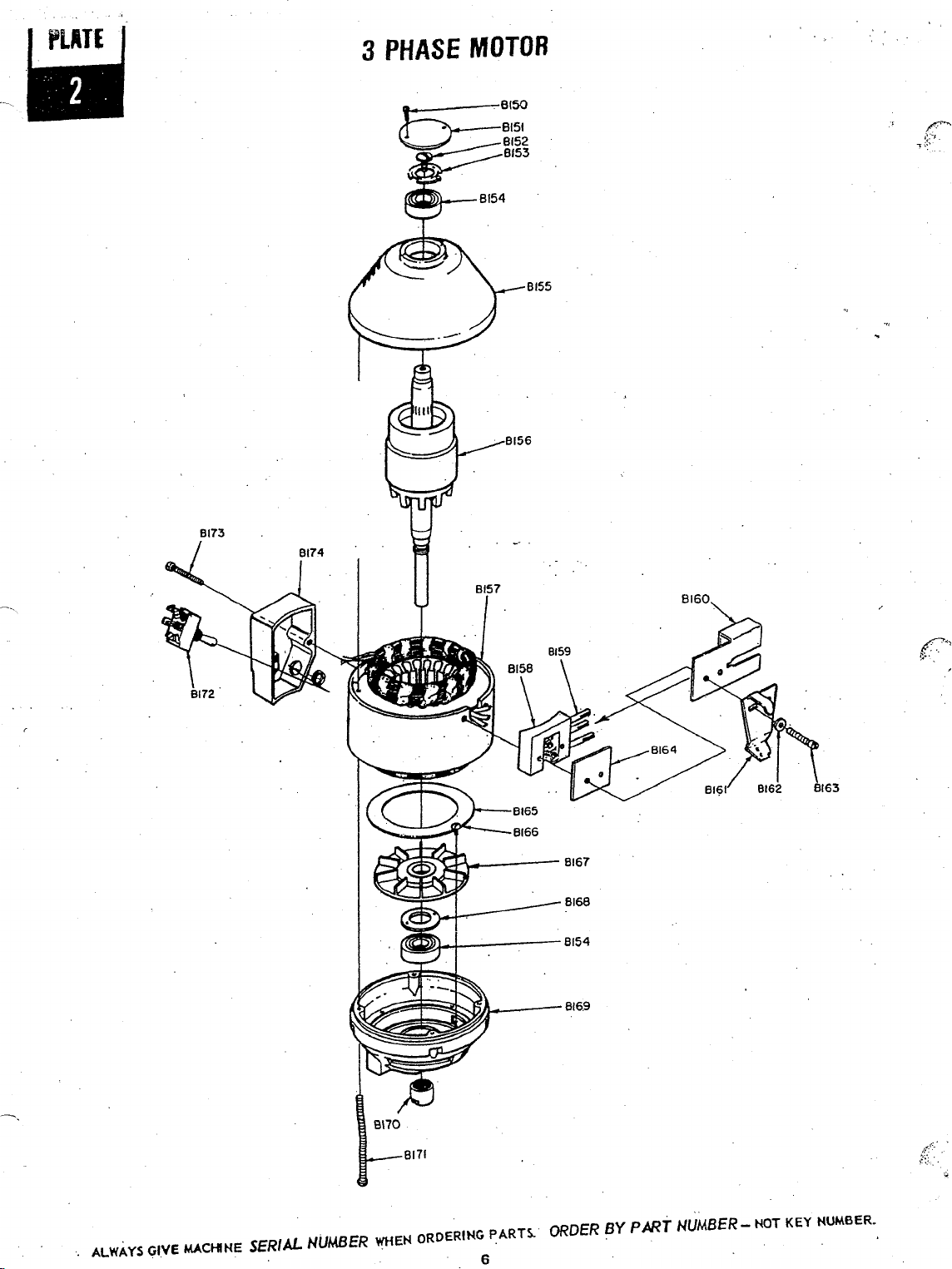
STANDARD
WITH
GLIDING
GRINDER & ROLLER
PLATE
8203
STANDARD SIZE IS
MARKED.
HERE
~~820<
i -azoz
I
i
I
8239
8238
8251
8250
8243
!f.~:.;·)
. l
8237
ALWAYS
GIVE
MACHINE
SERIAL NUMBER
WHEH
ORDERING PARTS.. ORDER
8
BY
PART
XY
ROLLER PLATE
NUMBER-
NOT
KEY HUMBER.

PARTS
liST
3
KEY
NO.
. 8201
8202
8203
8204
6205
B206
8207
'£!208
6209'
8210
8211
8212
8213
8214
8215
8216
8217
8218
8219
8220
8221'
6222
R223
8224
8225
8226
6227
8228
8229
8230
8231
8232
8233
8234
.
8235
8236
8237.
8238
8239
PART
NO.
323PJ
323PA
323J
323H
323M
323C
333
332
334
335K
802S
335A
.
335B
335C
3350
335XA
335X8
.
335XC
335XD
'336
3li1C
3410
342
518W
5108
510C
31.1G
318A
317H
.317M
3170
317E
1256
311W
311S
328T
328V
.348J
348A
348M
~c
348S
313K
l13R
- 313H
313N
337
340T
.,
3405
337P
340
339P
437
438W
313S
·339M
340
313L
337J
337L
3918
391E
391G
·
JS1H
391K
391M
319J
319H
319M
319C
DESCRIPTION
Pinion
Pin-#£
Pinion
Pin-
Pinion-
R4
or
PinionPinion-
248)
Pinion-
86
or87)
Trigger
Screw
Trigger
Trigger
Spring
Link
Knuckle
Screw,
6 x
Link-
4"
Link-
59
Link-
86
Link-
37
Link
with
Link
yJith 332, 334 - 59
Link
with
Link
with
Link
Screw
Handle
Assembly
Offset Handle Assembly
. Screw, 8 x
Washer
Lock
Nut
Screw, 10
Grease·
Cup··
Standard - 6 (4'-'l
StandardStandard - 248
Standard Standard Rollpin
Lock Washer
Screw.
12 x
Track (except
Track (4"1
Grease
·Circulator -
(for
standard marked 6) ·
Grease
Circulator
(for
standard marked
Grease
Circulator -
(for
standard marked
Grease
Circulator -
(for
standard marked 26
Screw,
4 x
. Throat Plate
Throat Plate
Throat
Plate, Slit-ter
Plate, Neckwear,.-
Throat
Roller Plate
8-1/4" x 5-1/2"
Standard Screw,
Standard Screw
Lip
Pin
Lip
Screw
Roller Shaft
Roller Shell
Washer
Throat Plate
Screw,
RoUer
Shaft
Lip Screw
Plate
Throat
Lip
Spring.
Roller
Plate
Trunnion
Trunnion Washer
T
~nnion
nnio.n
T
Trunnion Washer 1¥9·.002"
Trunnion Washer
·
Gear
with
(for
with
Gear
(for standard marked 59)
Gear
with
(for standard marked 248)
Gear
with Bearing -
{for standard marked 86
Pinion
all
other
#6
(for
~tandard
61
#9
(for
standard marked 59)
#248
(for
standard marked
#5
(for
standard marked
3/1GBind.
& 87
332,
334
- 4'.'
332, 334 -
332,
334-'
3/4
Oval
Hd.
x
3/8
Set
59
(SY."I
(511."1
86
(6"1
87
{7")
5/8
And.
4"1 _ ·
.m5
-
ml
#248
#5
3/16'Fiat
with
only
Lip
Washer
Washer l¥5·.002"
Washer NS-.005"
Bearing-
standard marked
Bearing - =9
Bearing·-
for
59, 86, 37
for
4"
Lip
Rear
with
with
Lock
Hd:
~7
& Rollers -
(20.9
Hollers,
Rollers,
66·.005"
#9·.005"
H6·.002"
..S
=248
pinions
marked
Hd.
86 & 87
31
Hd.
591
2481
.
or
871
: B271
·em
x 13.9 em)
Sack B279
Front
R4
or
61
=5
or
871
KEY
NO.
8240
8241
8242
8243
B244'
8245
8246'
6247
6248
8249
B250,
8251
B252
6253
8254
8255
B256
6257
8:258
6259
8260
8261
8262
8270
8272
8273
B274
8275
B276
B277
8278
8280
8281
B282
8283
8284
B285
6286
8287
8288
PART
NO.
320J
320A
320C
321J
321A
321C
321CW
347J
347A
347C
30303
30307
30310
30311
30322
30324
30325
30326
322J:
322A
322C
326J
326A
326C
·
349A
329A
3298
- 329C
3290
3295.
329LC.
329LS
329LW
329L328Z
331S
329LW
328J
328Z
328F
328
'.
330
330N
328E
8225
B1.8S
337C
340T
340S
427
329LW
438W
313S
339T
437
340
431A
329LW
340
'433B
.
802S
340
329LW
431B
430A
327K
390A
3908
390C
3900
390S
22028
DESCRIPTION
Gear Bearing (200K.) -
Gear Bearing
Gear Bearing (104) -
Bearing Lock - #6
·Bearing Lock Bearing Lock -
Washer, Bear!ng
Thread
Thread
Thread
KnifeKnifeKnifeKnifeKnife,
Knife,
Knife,
Knife,
· Gear
Gear
Gear
Knife
Knife Lock - 59
Knife
Gear
Knife
Knife
Knife
Knife
Screw, Guard Carrier·
Spring Cup
Spring
Washer
Guard Carrier
Screw, 6 x 7/16
Screw,
Washer
Coil Spring
-
S_crew,
Grinder Frame
Grinder Frame-with Stones
·Stones
Stones Only, Pair
Check Spring
Screw, 6 x 1/4 Bind. Hd.
Screw, 6 x
XY
ROLLER
XY
Roller Plate
9-3/4".x6-3/4"
Standard Screw, Rear
Standard Screw
Screw, 10 x 7/16
Washer
Washer
Screw,
XY
Roller Shafts
Front & BacK.
Roller Shell
Screw
Shaft
Washer
Screw
XV
Lip
Screw,
Screw
Washer
Shaft
XY
Roller Plate
PARTS NOT
Adjustable Knife Key
Backguard - 54
Backguard - 59
Backguard - 86 •
Backguard - 87
Backguard Screw
Tube
(103)-
*l
or
"1'5
Lock-
Seal
- :.6
Seal
-~ or
Seal
- ,.5
(for
4"
(for
5-1/4"
(for
6"
Cforim
7"
High
Speed
High
High
High
ScrewScrewScrew-
Lock'Lock
Cap-
GuardGuardGuard Guard--
8 x 3/8 Rnd. Hd.
6 x 7/16 F'il. Hd.
with
Throat Plate
for
Lip, Long
Spring
6 x 3/16 Bind. Hd.
for
Up,
of
Grease
Steel-
Speed
Steel-
Speed
Steel -
Speed
Steel -
4"
·
59 -..
_.
86 &
87
4"
-:-
86 &
87
59
4"
5-1/4''
6''
7"-
Fil.
Only
Bushing, Pair
1/4
Flat. Hd.
PLATE
with
(24.7cmx17.1
Flat
'!Yith
Short
Lip
ILLUSTRATED
41<248
541
59)
86)
Hd.
Lip
Hd.
m1
..9 or ;r248
;;5
#248
#5
4"
5-'1/4"
6"
7"
& Rollers
Rollers,
em)

STANDARD
WITH
#15
GRINDER & ROllER
PLATE
.,.:-·
8316
STANDARD
MARKED
6302
8301
v
SIZE
HERE
IS
-
-~
8337
~
8336
8335
8370
8345
8338
8334
'
8333
8332
ALWAYS
GIVE
MACHINE
SERIAL
NUMBER
WHEH
ORDERING
10
PARTS.
ORDER
9390·
8391--®
8392~
BY
PART
. I
(!)...8384
$.....83s5
h386
67
I
~
NUMBER-
XY ROLLER
f=i
I
·~
8'!.93.
NOT
I
I
8394
KEY
PLATE
6397
6396
6395
.
NUMBER.

LIST
KEY
NO.
8336
8337
B338
8339
8340
8341
B342
8343.
8344.
8345
8346
8348
9349
8350
8351
8352
8354
8356
B356
B357
8358
83598360
8362
B364 802S
8365
8366
8367
8368
8369 329LC
8370 329S Screw,
8380
B38t
8382
8383
B384
8385
B386
8387 339T
8388
8389
839()B391 329LW
B392 340 Screw
B393
8394
8395
8396 329LW
8397
8398
KEY
NO.
8301
8302
.8303
8304
B305
.B306
B307 802S
B308
8309
8310
8311
8312
B313 348J
B314 388T
B315
B316
B317 340T
8318
B319
8320·
8321
8322
8323
8324
8325
8326
8327 337J Lip Spring
8328
8329
8330
8331
8332 320J
8333
8334 347J
8335
PART NO.
323PJ Pinion Pin - #6 Pinion
323PA
323J
323H
323M
323C
341C
3410
342
518W
510C . Screw, 10
5108
311G
311W Lock
311S Screw, 12 x
805P
421
348S Screw, 4 x
34BA
348M
348C
388H Standard
388W
3880 Standard
388E Standard
313K
313R
313H Throat Plate, Hospital 8361
313N .Throat
337
.340S Standard Screw
337P
340
339P
437
438W
313S Screw, Throat Plate
339M Roller Shaft
340
313L
337L Roller Plate
3918 Trunnion
391E
391G Trunnion
391H
3.91K
391M.
319J
319H
319M
319C
320A
320C
321J
321A
321C
321CW
347A
347C
30303
30307
30310
30311
30322
Pinion
Pinion PinionPinion
marked
·Pinion
86
Handle Assembly
Offset Handle Assembly
Screw, 8 x
Washer
Lock
Nut
Grease
Screw,
Washer
Roll
pin 8347
Cap
Screw
Grease
(for standard marked 6)
Grease
(for standard marked 59)
Grease
(for
Grease
(for
Sta$rd
Standard
Throat
Plate
Plate
Throat
Plate, Neckwear
Roller Plate
8-1/4" x S.1/2"
Standard Screw,
Lip
Pin
Lip
Screw
Roller Shaft
Roller Shell Only
Washer
Lip
Screw
Throat
Plate Lock
Trunnion
Ttunnion
Trunnion
Trunnion
Gear
with Bearing - #6
(for standard marked 6}
Gear
with Bearing - #9
(for standard marked 59)
Gear
V~~ith
(for standard marked
Gear
with Bearing -
stangard marked 86 or
(for
Gear
Bearing
Gear
Bearing
Gear
Bearing
Bearing
Lock - #6
Beari~g
Lock
Bearing
L.ock
Washer,
Seal
Thread
Thread
Seal
Thread
Seal
KnifeKnifeKnifeKnife
-7"
Knife, High
PARTS
DESCRIPTION
Pin-
all other pinions
#6
(for
standard marked 6)
#9
(for
.;..
- #5
or87)
Cup
6 x
Circulator - #6
Circulator - #9
Circulator-
standard marked 248)
Circulator - #5 8353 387
standard marked
for
for
for·#15
for
for
Washer
Washer
Washer
Washer
Washer
Washer
Bearing - #248
Bearing Lock - #5
4"
5-1/4"
6"
standard marked 59)
#248
(for
~48)
3/4
x
3/16
3/16
tor
with
with
with
Lip
standard·
(for
standard marked
Oval Hd.
3/8
Set
Bind. Hd.
5/8
And. Hd.
Flat Hd.
#248
#16
Grinder-6 (4")
#15
Grinder
Grinder-
#15
Grinder-
#1
6 Grinder
69, 86, 37
for
4",
87
Lip & Rollers-
(20.9cm x 13.9.cm.) B363
Rear
Rollers, Beck
Rollers,
#6-.005"
19-.005"
15-.002''
#5-.005"
19·.002''
#6-.002''
#5
{200Kl
- #6
(103)-
H041-
-
- lr3 or #248
- #5
Speed
..:..
#9 or #248
- #5
m;
!for
(for 59)
!for
(for
Steel-
#9
#5
541
86)
871
86
or
-·59
248 (5-1/4"1
86
..,.
87 (7"1
Front
2481
871
or #248
4"
87)
(6-1/4")
(6'1
4
PART
NO.
30324
30325
30326
322J
322A
322C
326J
326A
326C Knife Lock - 86
349A
383A
415N
381A
382
381T
381S
381
3855
384
.
380
380A
1341
423P Pin
386B
8400
386
335K
332
333
1341
386
385T
385S
838N
310F
310K
329LW
310H
3108
389
329A
3298
329C
3290
329LW
329LS Spring
337C
340T
3405
427
329LW
438N
313S
437 Roller Shell Only
340
431A
433B
ao2s
340
4318
430A
327K
390A
3908
390C
3900
390S
22028
Nut
Tail Bushing
Spring, Stone Shaft
Stone Shaft ·
#15
Screw,
#15 Grinder Frame only
· #15 Grinder Complete
#15 Grinder Complete
Retaining Ring
#15 Grinder
Retaining Ring
Coil Spring
#15
Link
Trigger
Trigger
Retaining
#16 Grinder Bracket
#15
Screw,
Nut
#15
Gooseneck
Washer
Screw, 8 x 5/16 Bind. Hd. ·
Screw,
Screw,.6
#15
Knife Guard Knife
Knife Guard
Knife Guard W!lsher
Spring
XV
XV
Standard
Standard Screw
Screw, 10 x 7/16 Flat Hd.
Washer
Washer
Screw, Throat Plate
XV
Screw
Shaft
Washer
XV
Screw, 6 x 3/16 Bind. Hd.
Screw
Washer
Shaft
XY Roller
PARTS NOT ILLUSTRATED
Adjustable Knife Key
Beckguard • 54
Backguard • 59
Backguard • 86
Backguard - 87
Backguard Screw
Tube
DESCRIPTION
Knife, High
Knife, High
Knife, High
Gear
Gear
Gear
Knife
Knife Lock - 59
Gear
AdJusting Bushing
#15
Frame, Bracket
Grinder Link
Speed
Steel -5-1/4"
Spited
Steel -
Speed
ScrewScrew - 59
Screw - 86 & 87
Lock-
Cap- 59
Grinder Stones only, pair
Grinder Stones
6 x 1/2 Fit.
Knuckle.
4"
4'!
Shaft
Steel -7"
&
87
·
with
Hd.
& Stones
Screw
Rin~
Grinder Bracket
6 x
1/2
Grinder Gooseneck
for 3 phase
(3
phase),
x 3/16 Bind.
Grinder Guard Carrier
Guard-
-
Cup
Guard Carrier
ROLLER PLATE
RoUer
Plate
9-3/4"
x 6-3/4" (24. 7
Screw,
Roller Shaft with Rollers,
&
for
Lip, Long
Lip Spring
for
Lip, Short
Plate
of
Grease
Back
Front
for
Fll.
Hd.
motor
8 x 1-3/8 Fil.. Hd.
H"d.
4"
5-1/4"
6"
7"
with
Lip &
Rear
Lip
6"
Bushings, pair
with
for
37
37
Rollers-
em
x 17.1
em)

(continued from
4-3.
To
Adjust Play
The gear
gether initially to obtain a close
the gear and pinion wear
(or
backlash} between the teeth on the gear and the pinion.
Provided the gear bearing
movement
gear and the
trunnion washers (8238). ·Remove the gear (see paragraph
3-6},
and take out the thinnest trunnion washer. These
trunnion washers
visable
order to check to
There must always
gear and pinion
moving the trunnion washer, it
gear and gear
4-4.
then the bearing
knife key. The bearing (B240) isremoved from
tapping it lightly from the opposite side
Care must
When the bearing
gear and
Into the gear
damage the balls
to
T.o
Replace the Gear Bearing
The gear must
lightly oil it. The new gear beating
page
3}
In
Gear
(B239)
of
knife) the backlash between the teeth on the
pinion
remove the thinnest trunnion washer first in
wilf
screw to check the backlash.
lock (B24l) should
be
taken not to injure the teeth
is
by
lightly tapping its outside rim so
of
the bearing. To make sure
and pinion (B202) are lapped
fit.
Over a period
so
that there
is
in
can be reduced by removing one
are
available in two thicknesses.
see
if
the backlash has been eliminated.
be
a slight amount
screech when run together. After
be
removed from the machine., and
removed, clean the inside seat
is
an increase in play
good condition
of
backlash
is
necessary
be
unscrewed with the
with a small mallet.
may
that
to
replace the
the
of
be pressed
of
(no
or
It
is
or
gear by
the gear.
of
as
not
the bear-
ing is seated firmly in the gear, place the old bearing on top
of
the new one and tap the outside rim
to
force the new one
bearing into position by replacing the gear bearing lock.
all
the way into the gear. Lock the
of
to-
time
4-5. To Replace Motor
side
two
Loading Spring
by
ad-
Switch Box (B42). Remove the
Lift
large screwdrivenlightly
the
ping upwards lightly. Tap bearing out from inside the hous-
re-
ing (through hole .in Stationary Switch B 18). Replace Top
Housing onto Field and tighten Motor Bolts. Then put in
new bearing
ping
prevent harming inner
three screws (8219). Pull Pinion (B202)
Unscrew Armature
Bolts {B31) and then Bottom Housing (B28). Remove
the
Bearing Lock
out. Clean the seat for bearing in Bottom Housing and
to
ly oil. Replace bearing
assemble motor. Tighten Armature Nut securely.·
a) Top Housing
Remove
(Bl4).
turning clockwise. Loosen the two screws
off
Top Housing
by
placing old bearing
it
into housing. Rotate old bearing wheh tapping to,
b)
Bottom Housing Ball Bearing
Remove
(827)
Bearing
BaU
Bearing
the two screws
Unscrew Armature Screw (B13A) •
(Bl6)
from Field (B2I) by inserting
in
to
or
outer race
motor
from standard by unscrewing the
Nut
(B30). Take
with
Knife ·Key, and tap old bearing
as
described in para. 4-Sa and
(815
or
(8
I
i),
Cap
four
Motor Bolts (831).
the ventilation slots and tap·
on
top
of
of
new bearing.
(B
15
orB
off
armature shaft.
out
the. four Motor
the old bearing
Bl 54)
(8
13), and
(843)
holding
it while tap-
154).
light-
re-
HUMBERS IN PARENTHESIS FOLLOWING
Maimin
tr
84
7. 709.2500 .
Technology
USA
800.243.4645
PART
Group,
NAMES ARE
rnc.
~·
84
7.
KEY
NUMBERS
70
N.KingStreet,EikGroveVillage,IL
709.2599
FROM
PARTS
PLATES-
_Q www.maimin.com · sales@maimin.com
HOT PART NUMBERS
60007
USA,

59supp1e59supple
H.
Maimin
Co.,
Inc.
P.O. Box 549, Rte.341
Kent,
CT
06757
USA
SUPPLEMENT PARTS
MODEL 59, SINGLE PHASE ROUND KNIFE
ONLY
Key No.
Bl3
Bl4
Bl6
FOR
R59-33,
SERIAL NUMBERS BEGINNING
OR
Part Number
446Q
15195
365K
365L
SHEET
R59-43 AND ENDING
HOLE PLUG %"
WAVE
STARTING
GASKET-
FOR
WITH
Description
MAIMIN
MACIDNE
WITH
12532
WASHER
OR
SWITCH
STARTING
2/04/00
1
of
Page
1
R59-13, R59-23,
IDGHER
SWITCH
Bl56
Bl57
B202
B302
15286B
15286B
323HA
323HS
323HA
323HS
302P
857N
Always give SERIAL NUMBER when ordering parts.
R59 SINGLE
(DESIGNATE
R59 SINGLE
(DESIGNATE VOLTAGE)
PINION
PINION SPACER
PINION
PINION
PARTS
NOT
ILLUSTRATED
TOP HANDLE
KEPNUT (TOP HANDLE) 2
8-32
Order
by PART NUMBER not Key Number.
PHASE
VOLT
PHASE
#9
(FOR
#9
(FOR
SPACER
AGE)
59)
59)
MOTOR
MOTOR
ASSEMBLY
ASSEMBLY
59supple59supple

H.
Maimin
P.O.
Kent,
Cd.;
'
Box 549
CT.
06757
'.
Inc.
U.S.A.
Key No.
Bl2
B23
B43
BlSO
Bl73
B209
B210
B228
B259
B283
B320
B324
B393
SUPPLEMENT
Part
802S
331S
310B
802S
310B
336S
464S
436S
23007
330L
330M
433A
436S
23007
441S
433A
PARTS
No.
PARTS
LIST
FOR
ALL
NOT
ILLUSTRATED
ROUND
KNIFE
Description
Screw,
Screw,
Screw,
Screw,
Screw,
Linkage
Soft
Lip
6 X
8-32 X 3/8
8-32 X 1;
6 X
8-32 X 1;
Screw
Grip
Screw
Handle
Washer
Stone
Stone
Assembly,
with
Spring -Lip
Lip
Screw
Washer
Screw,
6-32 X 5/16
Spring -Lip
MACHINES
3/16
Pan
Fillister
3/16
Pan
Fillister
Assembly
Pair
Bushing,
Head
Round Head
Head
Head
Head
Pair
Fillister
Head
Always
464E
464NB
give
Order
machine
by
PART
Handle
Handle
SERIAL
NUMBER
NUMBER -not
Stud,
Nut,
when
3/8-24
3/8-24
order~ng
Key Number.
X
1~
Hex X
parts.
Soc.
3/4
Set
Lg.
Screw
5/16/95

~ent,
CT.
-~
,06757
~-
Parts
List
Supplement
for
Round
with
11,
SERIAL
21,
Example:
Key
No.
Bl3
Bl4
Bl6
Part
446Q:
15195
15292
No.
15293
365K
365L
Bl7
B20
497P
15301
15305
15302
-~
B21
15289
15309
15290
15303
15306
15307
B31
.15295
Knife Machines
NUMBERS
31,
41
in
second group
RXX-11-XXXXX
Description
Hole
Wave
Top
Plug
Washer
Housing
Cover Starting
Gasket ~ Starting
· .support Washer
R248
Armature
R37
Armature
RS4
Armature
R59
Atma.ture
R87
Armature
Shell & Field
Shell & Field
R3 7 Shell & Field
R37
Shell & Field
Bolt
8-32 X 4
containing
3/4"
Starting
Switch
Assembly
Assembly
5/8
Switch
Switch
120V
.•
220V.
Ass~fnb.ly
Assembly
Lg.
Round
120V.
220V.
Hd.
3/23/93

·H. Maimin Co., Inc.
P.O.
Box 549, Route 341
Kent, CT 06757 USA
Tel: 860-92746001800-2434645
Fax: 860-9274703
Key
Number
813
814
816
820
821
831
8202
8302
SUPPLEMENT
PARTS
MODEL
ONLY
12,
FOR
22,
SERIAL NUMBERS CONTAINING
32,
42,
82
Example:
Part
Number
4460
15195
15292
15293
365K
365L
15361
15290
15303 Shell
15295
323HA
323HS
323HA
323HS
Description
Hole Plug 3/4"
Wave Washer
Top Housing
Cover - Starting Switch
Starting Switch
Gasket R59 Armature
Shell
Bolt 8-32 X 4-5/8 Lg. Round Hd.
Pinion
Pinion Spacer
Pinion
Pinion Spacer
SHEET
FOR
MAIMIN
59
IN
THE
SECOND
GROUP
R59-XX-12345
Starting Switch
& Field Assembly 120V ·
& Field Assembly
#9
(For 59)
#9
(For 59)
220V
NOT
PARTS
302P
857N
Top Handle
8-32 Kepnut (Top Handle) 2
ILLUSTRATED
g\apps\works\SPR59-01.WPS
on
7/23/97

MAIM
IN®
MODEL
37
(see
&
Parts
List
STANDARD & ROLLER
Malmln
Catalog
Round
for
Knife
motor
Instructions
and
grinder
Al35
PLATE
parts)
Alii
All2
KEY
NO.
PART
NO.
A101
A102
A103
A104
A105
A106 337C
A107
A108 340S
A10Ba
A109
A110
A111 339T
A112
A113
A113a 4318
A114 329LW
A115
A116
A117
A118
A119
A120
3410
342
618W
610C
610B
311G
356A
388R
340T
427
329LW
313S
438W
340
431A
340
4338
B02S
430A
313K
391G
DESCRIPTION
Offset Handle Assembly
Screw, B x
Lock Washer
Screw, 10 x
Nut A124
Grease Cup
Standard for Gliding
Standard
XY
Standard Screw, Rear A129
Standard
Screw, 10
Washer
Screw,
Washer
XY
Screw
Shaft
Shaft
Washer
Screw
XY
Screw,
XY
Throat
Trunnion Washer
3/4
3/8
for
#16
Roller Plate with
lip
and Rollers A128
Screw
x
7/16
Throat
Plate
Roller Shafts with Rollers -
Front
and Back
for
Lip, Long
for
L.ip,
Short
L.ip
Spring
6 x
3/16
Roller Plate Lip
Plate for 37
All3o
Oval
Hd.
Set
Grinder-
Grinder -
Flat Hd. A131
Bind. Hd.
#5
37
37
KEY
NO.
A121
A122
A123
A126
A126
A127
A130
A132
A133
A134
A135
A136
A137
For maintenance and repair instructions see Maimin
Round Knife Instructions
To remove
(Al28):
Take
out
(Al34); then the two screws
(Al32).
Unscrew Gear Screw
left-hand thread). Lift
Gear Screw (A 131) counter-clockwise
thread). Remove Bevel-spur
PART
NO.
364
320C
321C
321CW
30311
30326
326C
322C
391A
360
320J
321J
351
362
348S
353
3168
3238
323PA
PARTS
300NA
300SA Armature Screw - 37
390F Backguard - 37
"",.,,....,....,.,
DESCRIPTION
Spur
Gear with Bearing
Gear Bearing ( 1
Bearing Lock
Washer, Bearing Lock
-7"
Knife
Knife, High Speed Steel •
Knife Lock
Screw (Left Hand Thread)
Gear
Trunnion Washer
Bevel
-Spur
Gear with Bearing
Gear Bearing
Bearing Lock
Gear
Cover
Screw,
Crescent
Screw,
P.lnion
Pinion Pin
NOT
Armature
ru.1 ~ ..
(200K)
Screw (Right Hand Thread)
Plate
4 x
3/16
Plate
4 x
1/4
(#8l
ILLUSTRATED
Nut-
P"l..-
&.lll!lft~n
Spur Gear
the two screws
out
04)
7"
#6
Flat Hd.
Rnd. Hd.
37
.._,_,..
& Parts List Catalog.
(Al21)
and Bevel-Spur Gear
(Al35)
and Crescent Plate
(Al33)
(Al26)
and Cover Plate
clockwise
(it
Spur Gear (Al21). Unscrew
(it
has right-hand
Gear (A 128).
lii"""V
...
uu.•n~n
has

H.
Maimin
P.O.
Box
Kent, CT 06757 USA
Tel: 860-927-4600/800-243-4645
Fax:
Co.,
Inc.
549,
Rout~
860-927-4703
341
SUPPLEMENT.
ONLY
13, 23, 33, 43, 83
Key. ·Part
Number Number
813
814
816
446Q
15195
365J
365L
821 153088
15076
15084A
8202 323CA
323CS
8302 323CA
323CS
FOR
SERIAL
Example:
PARTS
SHEET
FOR
MAIMIN
·MODEL87
NUMBERS
IN
THE
SECOND
CONTAINING
GROUP
R87-XX-12345
Description
Hole Plug 3/4"
Wave Washer
Starting
Gasket - Starting Switch
Motor assembly 120v/220v
Capacitor 270mFD
Capacitor Cover
Pinion #5 (For 87)
. Pinion Spacer
Pinion
Pinion Spacer
#5 (For 87)
.
Switch
PARTS
302P
857N
NOT
ILLUSTRATED
Top Handle
8-32 Kepnut (Top Handle) 2
g\apps\works\SPRB?-02
on
05/25/99

MAIMIN°
(see
.,
Malmln
Round
Knife
SLITTER
STANDARD
Instructions & Parts
List
Catalog
for
all
other
parts)
KEY
NO.
A270
A271
A272
A273
A274
A275
A276
A277
A278
A279
A280
-~
A281
A2S2
A283
A284
A285
PART
395H
395HX
395A
395AX
395C
395CX
395E
395EX
836N
421
427
395P
396H
396A
396C
396E
3408
427
3135
438W
329LW
3370
313T
427
392H
392A
392C
392E
436T
397
NO.
DESCRIPTION
Slitter
StandardSlitter Standard with
Slitter Standard
Slitter
S~andard
Slitter Standard Slitter Standard with
Slitter Standard - 87 (Give Sei'ial No.)
Slitter Standard with
Nut with Lock Washer
Cap Screw ·
Screw,
Support
Support for Slitter Standard - 59
Support for Slitter Standard - 86
Support for Slitter Standard Standard Screw
Screw,
Screw for
Washer for Throat
Washer
Rollerplate with Rollers for Slitter
Slitter Throat Plate
Screw,
Backguard,
Backguard,
Backguard, Slitter - 86
Backguard, Slitter - 87
Screw, 6 x 3/16 Flat Hd.
10 x 7/t6
Pin
-Support
for Slitter Standard - 54
10
x 7/16 Flat Hd.
Throat
(See
XY Roller
for component parts)
10
x 7/16 Flat Hd.
Slitter Slitter-
54 (Give Serial No.I ·
Support -54
-59
(Give Serial No.)
with
Support
86
(Give Serial No.)
Support -86
Support
Flat Hd.
to
Standard
Plate
Plate
Plate-
54
59
Filler Plate
Plate
-
59
- 87
87
3-
For
maintenance and repair instructions see Maim
Round Knife Instructions & Parts List Catalog.
.
---.
·····-
....
r.
.,,.,..
III:V
UIIUP.FR.
 Loading...