

Maidaid Halcyon Barista Compact Installation And User Manual

Barista Compact
Espresso coffee machine
Installation and user manual
Maidaid Barista Compact Installation and user manual V1.0
Installation
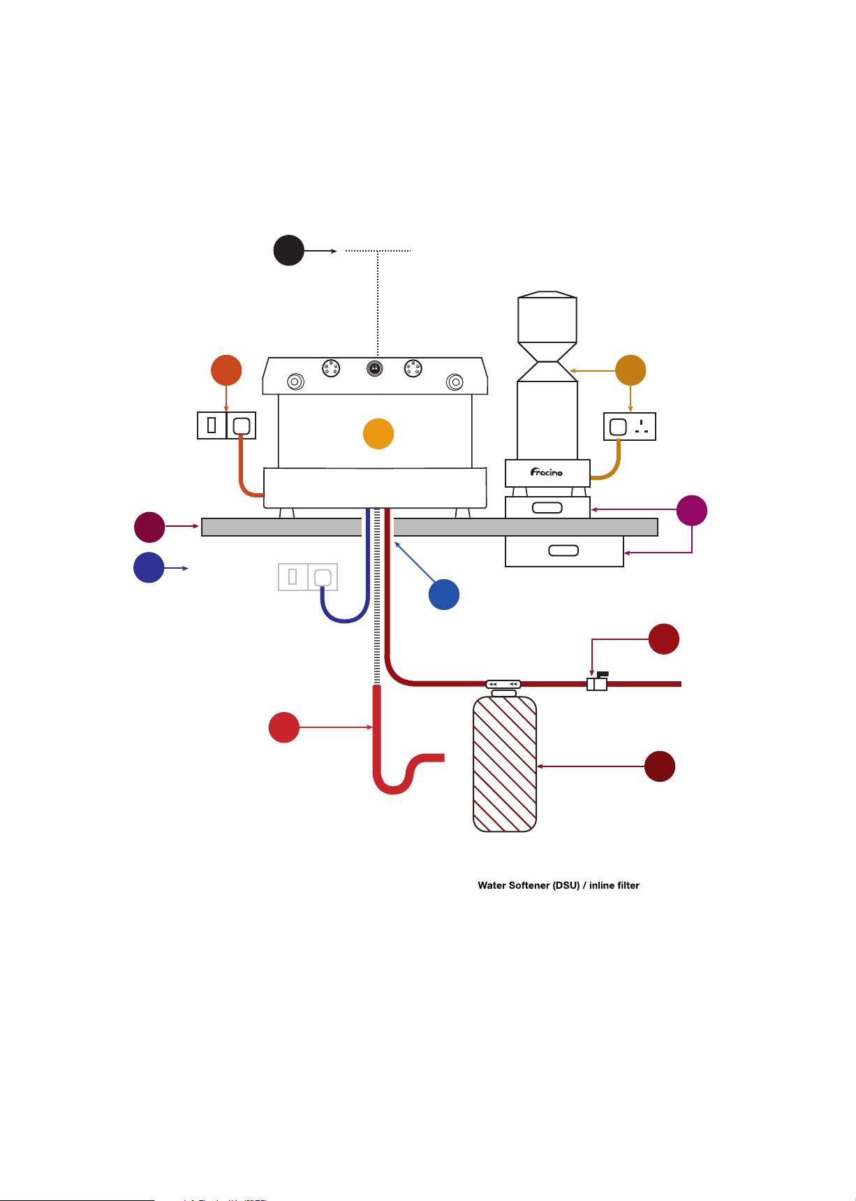
Overview
7
10
Power
(2nd Position
Switch or plug)
11
300mm
1
23
PowerPower
8
9
5
4
Coee Machine.
1
Grinder – 13 amp socket required.
2
Power connection for coee machine
(must be within 1 metre). Switch or plug.
3
1.5” (Minimum Diameter) Stand pipe for
waste as for washing machine.
4
¾'' B.S.P Washing machine type valve
5
for mains cold water with isolator handle.
Waste
6
if required.
Counter.
7
Under counter or under grinder
8
Knock-out drawer.
Hole in counter: 2'' Diameter.
9
Alternative position for power supply
(must be within 1 metre). Switch or plug.
10
Please ensure a gap of 300mm is maintained
above the top tray of the machine to allow for
11
cup storage and service access.
Cold
Water
(15mm)
6
Preparing for
Installation
1
A
Services and
equipment required for
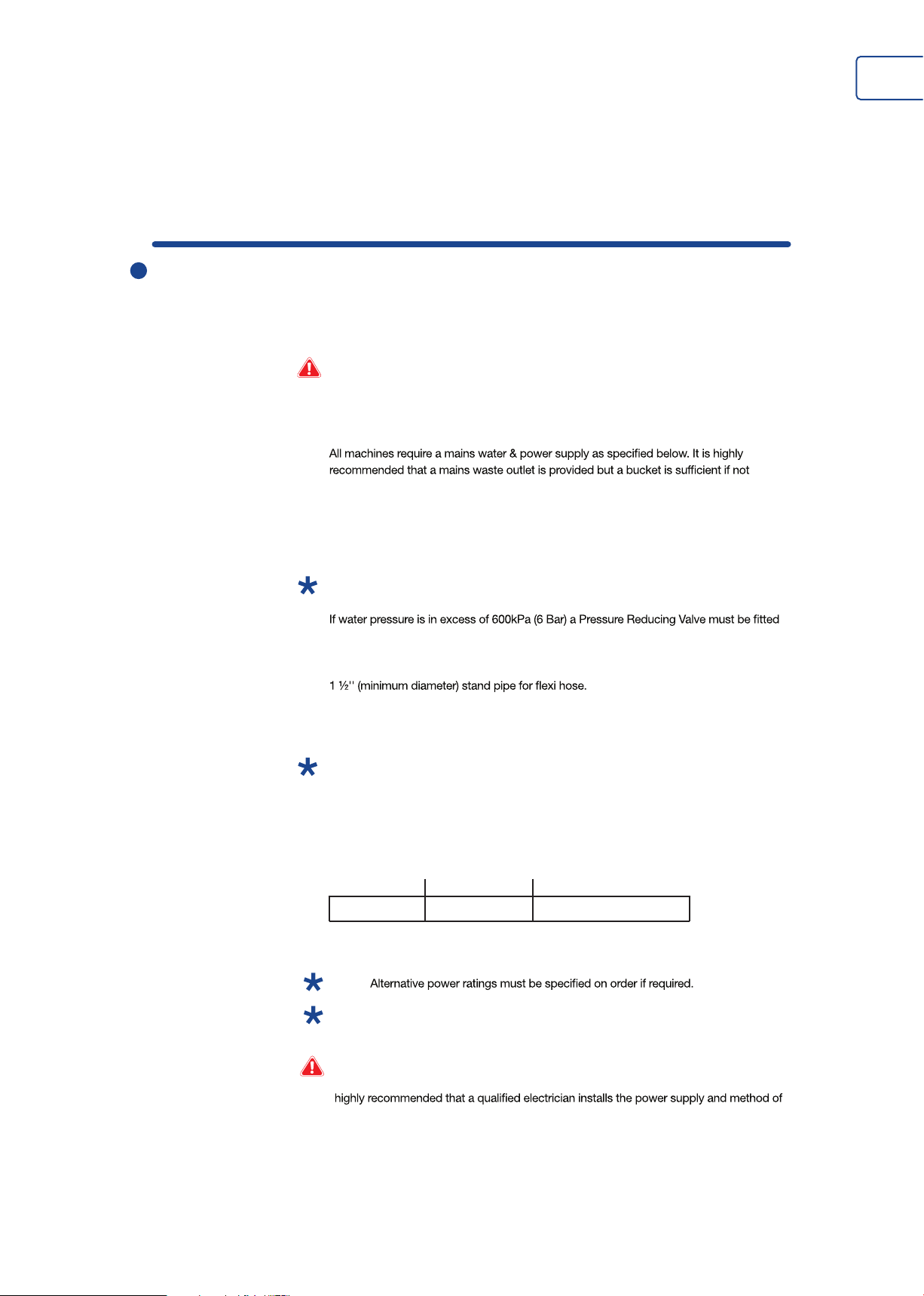
Warning: Installation of this appliance must only be carried out by trained persons
available. All services must be in place prior to installation. ALL CALLS TO UNPREPARED
SITES MAYBE FULLY CHARGEABLE.
Mains water:
15mm mains cold water supply with ¾'' BSP standard washing machine stop cock.
Note: Min inlet water pressure is : 100kPa (1 Bar)
Max inlet water pressure is : 600kPa (6 Bar)
and set between the above parameters, normally 300kPa (3 Bar).
Mains waste:
Water and waste connections to be directly beneath the location of the machine
installation
Power supply: As below
Note: Socket to be located on the same side of the coee machine that the grinder will
stand. (Recommended right hand side - see installation overview).
Grinders - All models 13amp
Coee Machines - Standard Power Ratings
Group kw amp
2 Group 2.85kw 13amp single phase
Note:
Note: The appliance must be installed in a location where the ambient temperature is
always between 5°C and 30°C.
Warning: The power supply and method of connection must comply with any national rules
or regulations which may be present in the country in which the appliance is installed. It is
connection BEFORE the appliance is installed.
B
Preparing the areafor installation
Note: The appliance must be installed in a location where it can be over seen by trained
personnel and its use and maintenance is restricted to trained personnel.
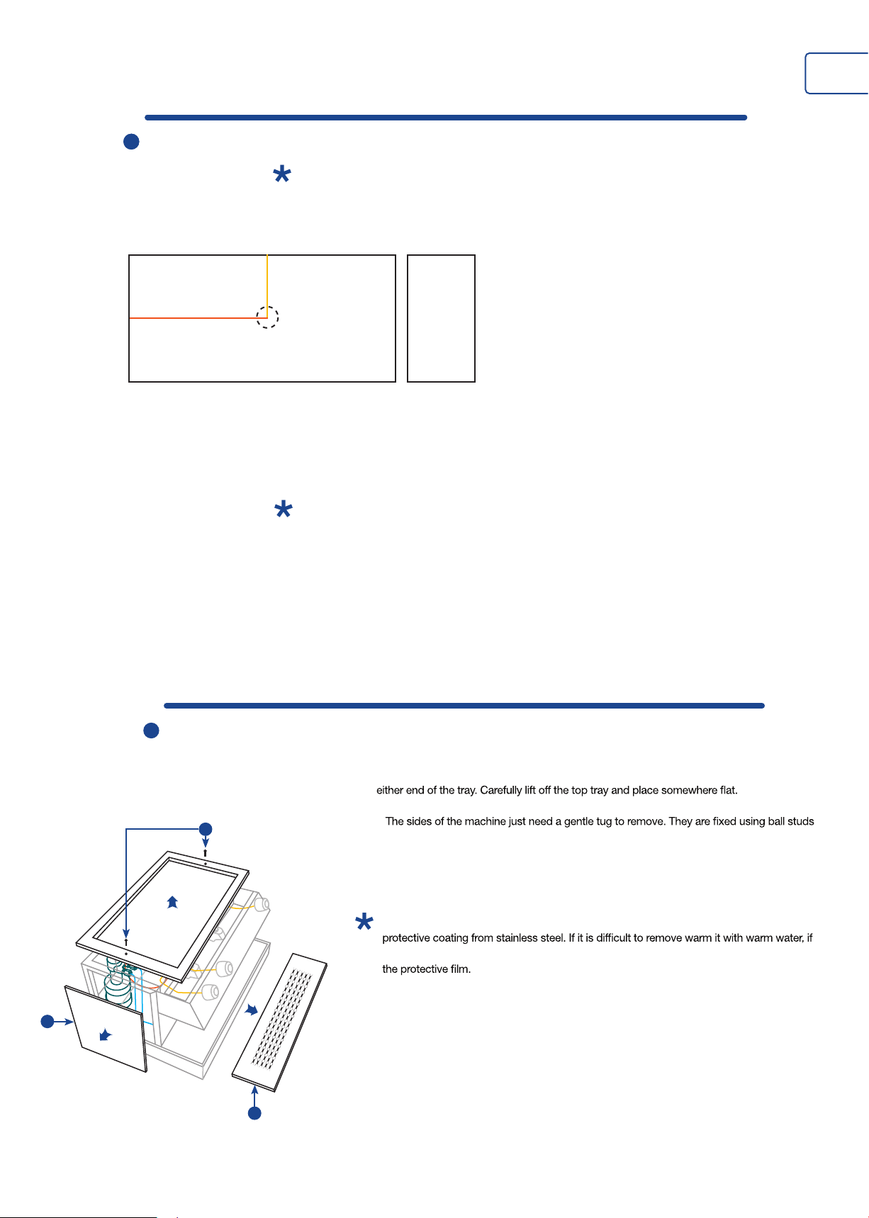
Plan view for drilling counter for Coee Machine Area for Grinder
(1)
110mm
(2)
300mm
(3)
240mm
Work out the location of the coee machine on the bar or counter and nd the position.
Drill a 2’’ hole using the measurements below as a guide. All the coee machines power
and waste connections feed from the bottom at the centre of the coee machine. These
connections then feed down through the 2’’ hole in the bar or counter.
450mm
2
(1) Depth from the back of the machine to the hole.
(2) Length from the side of the machine to the hole.
(3) Hole in counter: 2'' Diameter
Note: The power connections for the coee machine and grinder must be within 1 metre
behind or beneath the machine. The power point and method of isolation must be easily
accessible at all times.
The water and waste connections for the coee machine must be directly beneath it.
All services, including hole in bar counter, must be in place prior to engineer arriving to install
the coee machine.
Ensure that the surface the coee machine is to be placed on is suciently strong and stable
enough to carry the weight of the coee machine.
E
Preparing the machine for installation
1
1) Remove the top tray of the machine by locating and unscrewing the two M4 screws at
2)
for quick and easy access.
3) Remove the drip tray to reveal the waste funnel. This is done by lifting it upwards at the
front as it simply rests in place again for easy access and cleaning.
Note: Remove all packaging before working on / installing the machine and remove plastic
any glue is left on use a solvent like WD40 to remove it – DO NOT use abrasives to remove
2
3
Installing the
coffee machine
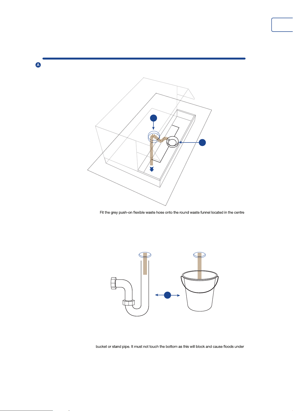
Connecting the waste pipe
3
2
1
1)
of the machine and tighten with the wormdrive clip provided. 2) Then feed the waste hose
under the machine and down through the 2” hole already cut out. Pull taught and ensure no
kinks are present in pipe.
75mm
3
3) Place the waste pipe into a bucket below the machine or into the stand pipe with a ‘P’ or
‘S’ trap to prevent smell. Ensure waste pipe is cut to length and is only 75mm into the
the machine. Clip or cable tie the pipe into position to prevent it from moving.
B
Connecting the water supply
4
1
2
1)
the water hose under the machine and down through the 2” hole already cut out. 2) Connect
this to a washing machine tap (Cold water supply) with ¾'' BSP male thread or to the water
debris entering the machine.
Note: It is highly recommended that the new hose sets supplied with the coee machine are
used. Old hose sets should not be re-used.
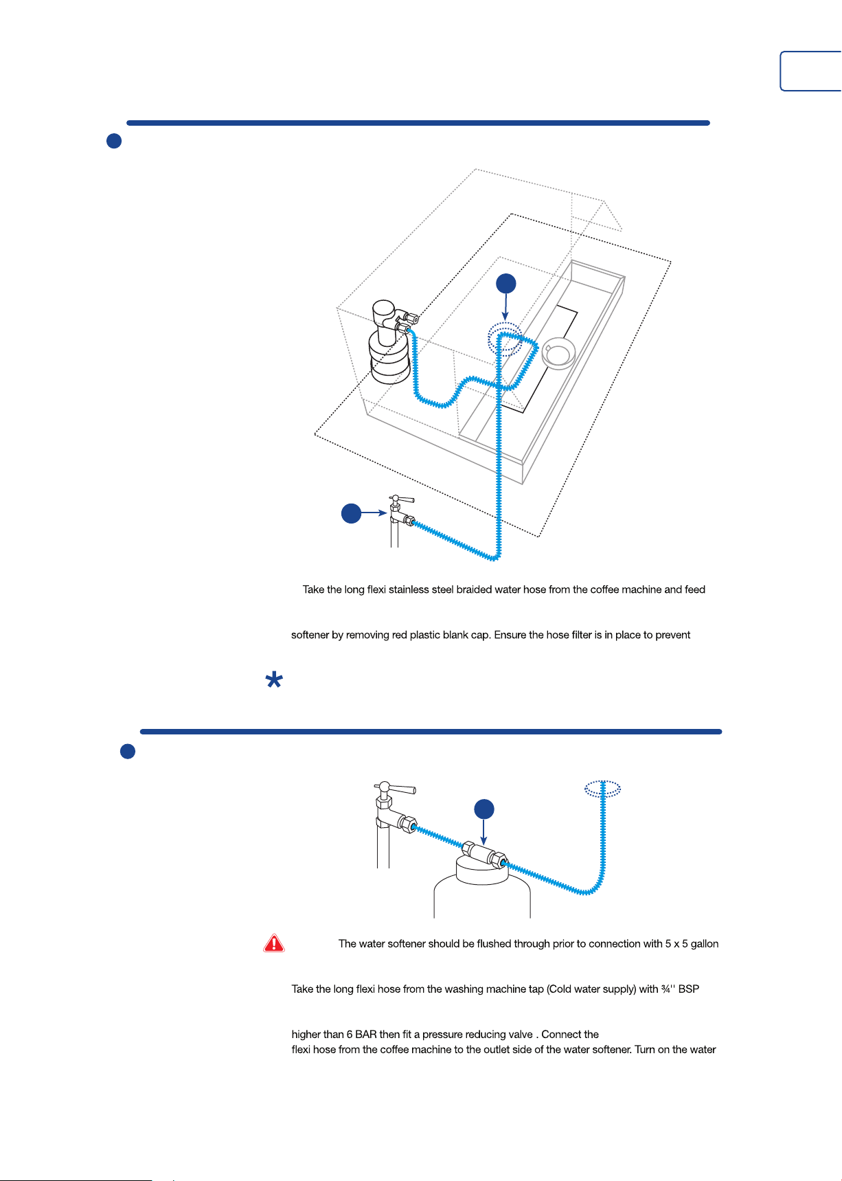
C
Connecting the water Softener (if required)
1
Warning:
(Approx. 25L) buckets or until the water runs clear.
male thread and connect to the inlet side of the water softener. 1) This is indicated on the
top label of the water softener. Ensure the water pressure does not exceed 6 BAR. If it is
supply and check for leaks.
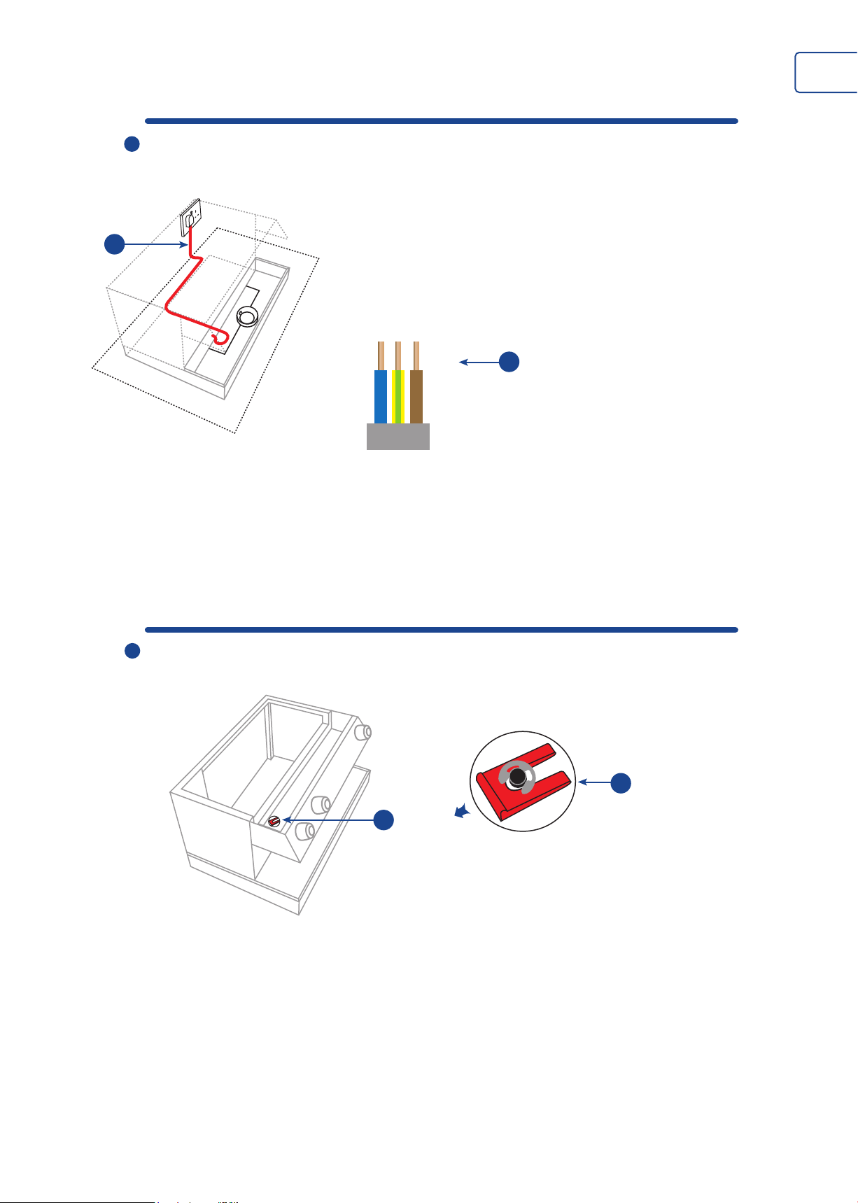
D
Connecting the power supply
5
1
Before turning
the machine on
1) Run the mains cable through the hole in the bottom of the machine or underneath to the
nearest power supply. Make sure your mains supply is within 1 metre of the machine and
has easy access for power isolation.
Single phase 13amp
2
Brown = live
Blue = neutral
Green -Yellow = earth
2) Connect the machine cable to a double pole isolator mains supply or 13 amp plug. The
power supply will depend on the size of the machine and the rating plate. The use of
commando plugs is good for ease of total isolation.
A
Remove the red air release valve clip.
1) Remove the RED plastic clip from the air release valve on top of the sight glass. Failure to
do so will cause air locks and milk to be sucked back into the boiler.
2) Slide the red clip out from under the E-clip. Do not remove the E-clip as this is needed
for the machine to function correctly and will cause the air release valve to come apart
if removed.
2
1
 Loading...