

Page 1
Wandeinbauventilatoren
Wall-mounted fans
Ventilateurs muraux
EN 20 ENR 20
EN 25 ENR 25
EN 31 ENR 31
Montage- und Betriebsanleitung
Mounting and Operating instructions
Instructions de montage et Mode d´empoi
www.maico-ventilatoren.com
Page 2

234
Page 3
Page 4
Page 5

Wandeinbauventilatoren
EN 20/ENR 20, EN 25/ENR 25
und EN 31/ENR 31
1. Warnsymbole in dieser Anleitung
Lebensgefahr!
Eine Nichtbeachtung kann zum Tod oder
GEFAHR
VORSICHT
2. Produktinformationen
Geräteübersicht, Abb. 1
1 Innenabdeckung komplett
1.1 Schutzsteg
2 Klemmenkastendeckel komplett
2.1 Dichtung
2.2 Schraube (3 Stück)
3 Flanschhülse komplett
4 Kondensator (ENR..)
5 Klemmenleiste (EN.. 3-polig, ENR.. 4-polig)
6 Klemmenleiste (3-polig)
7 Motor komplett
8 Flügelrad komplett
9 Außenklappen (= Zubehör):
9.1 Lamelle
9.2 Getriebemotor
9.3 Anschlusskabel
9.4 Schutzrohr
D Dübel (bauseitig)
S Befestigungsschraube (bauseitig)
X Typenschild
zu schweren Körperverletzungen führen.
Verletzungsgefahr/Sachschäden!
Eine Nichtbeachtung kann zu leichten bis
mittleren Körperverletzungen oder Sachschäden führen.
Ersatzteile sind fettgedruckt. Bei Ersatz-
i
teilbestellungen die Anleitungs-Drucknummer
(siehe Umschlag-Rückseite), die Gerätevariante und die jeweilige Positionsnummer
angeben.
Verschlussklappe „MK“ (siehe Abb.),
Verschlussklappe „BK“ oder selbsttätige
Außenklappe „AS“ (ohne Abb.)
Impressum
© MAICO Elektroapparate-Fabrik GmbH. Originalanleitung.
Druckfehler, Irrtümer und technische Änderungen vorbehalten.
Produktbeschreibung
EN..-Ventilatoren zum Entlüften. Nur in Kombination mit Außenklappe „MK“, „BK“ oder „AS“.
ENR..-Ventilatoren mit Reversierbetrieb zum Entoder Belüften. Nur in Kombination mit Außen-
klappe „MK“ oder „BK“.
EN.. und ENR..-Ventilatoren sind mit einem thermi-
•
schen Motorüberlastungsschutz ausgestattet.
Ventilatoren werden mit einer bauseitig bereitzu-
•
stellenden Schaltungskomponente ein- oder ausgeschaltet, siehe Schaltbilder Seite 16...19.
3. Technische Daten
Siehe Typenschild.
4. Umgebungsbedingungen und
Grenzen für Betrieb
Zulässige Höchsttemperatur des Fördermediums:
•
+40°C
Bei Betrieb mit raumluftabhängigen Feuerstätten
•
muss für ausreichende Zuluftnachströmung gesorgt werden. Die maximal zulässige Druckdifferenz beträgt 4 Pa.
5. Grundlegende Sicherheitshinweise
Allgemeine Sicherheitshinweise
Sicherheitshinweise vor Inbetriebnahme aufmerk-
•
sam durchlesen.
Anleitung aufbewahren.
•
Das Gerät darf nicht als Spielzeug verwendet
•
werden.
Montage nur durch Fachkräfte zulässig.
•
Elektrischer Anschluss und Reparaturen nur durch
•
Elektrofachkräfte zulässig.
Bei der Elektroinstallation und Gerätemontage
•
sind die einschlägigen Vorschriften, besonders
VDE 0100 mit den entsprechenden Teilen zu
beachten. In Räumen mit Bade- oder Duscheinrichtung z. B. Teil 701.
Gerät nur an fest verlegte elektrische Installation
•
mit einer Zuleitung von 1,5...2,5 mm² anschließen! Diese muss mit einer Vorrichtung zur Trennung vom Netz mit min. 3 mm Kontaktöffnung je
Pol ausgerüstet sein.
5
Page 6
Gerät nur mit auf Typenschild angegebener Span-
•
nung und Frequenz betreiben.
Vor Abnehmen des Klemmenkastendeckels [2]
•
das Gerät allpolig vom Netz trennen. Dazu Netzsicherung im Sicherungskasten ausschalten!
Veränderungen und Umbauten am Gerät sind
•
nicht zulässig und entbinden MAICO von jeglicher
Gewährleistung und Haftung.
Gerät nie ohne Innenabdeckung und nur mit
•
komplett montierter Außenklappe betreiben (Berührungsschutz des Flügelrades nach EN 294).
Bestimmungsgemäße Verwendung
EN..- und ENR..Ventilatoren zur Entlüftung von
•
Büros, Geschäfts- und Gewerberäumen, Gaststätten, Arztpraxen etc.
ENR..-Ventilatoren auch zur Belüftung.
•
Zur Aufputzinstallaton, an Wand, Decke oder
•
Dachschrägen.
Vorhersehbare Fehlanwendungen
Gerät auf keinen Fall einsetzen:
in der Nähe von brennbaren Materialien, Flüssig-
•
keiten oder Gasen.
für die Förderung von Chemikalien, aggressiven
•
Gasen oder Dämpfen.
in explosionsfähiger Atmosphäre.
•
Sicheres und korrektes Verhalten für
den Betrieb
Verletzungsgefahr! Keine Gegenstände in das
•
Gerät hineinstecken!
Gefahr durch sich drehendes Flügelrad! Nicht zu
•
nahe an das Gerät gehen, damit Haare, Kleidung
oder Schmuck nicht in das Gerät hineingezogen
werden können.
6. Montage
Funktionsstörung und Gerätebeschädigung durch streifendes Flügelrad bei
VORSICHT
•
•
•
•
•
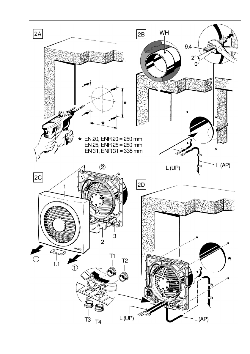
Wandeinbau (Abbildung 2A bis 2H)
A Dübellöcher anzeichnen und bohren, für Boh-
B Wanddurchbruch, Netzleitung [L] (Aufputz „AP“
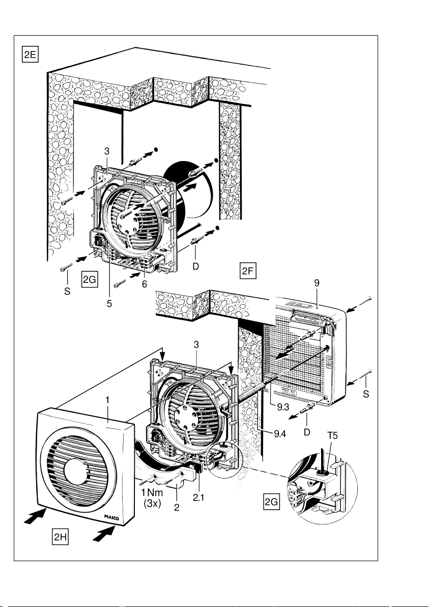
C Innenabdeckung [1] abnehmen. Die Abdeckung
D Gewünschte Leitungstülle [T...] der Flansch-
E Flanschhülse [3] mit geeignetem Befestigungs-
F Außenklappe gemäß zugehöriger Anleitung
fehlerhaftem Einbau!
Flanschhülse spannungsfrei einbauen!
Für ebenen Untergrund sorgen.
Wichtige Hinweise
i
Wanddicke EN/ENR 20, EN/ENR 25 = min. 105 mm
Wanddicke EN/ENR 31 = min. 130 mm
Ausreichend Platz zur Wand oder Decke berücksichtigen.
Um die Schutzart zu gewährleisten, müssen die
Leitungstüllen [T...] ordnungsgemäß, d. h. kreisrund und etwas kleiner als der Leitungsdurchmesser durchbohrt/durchstoßen sein.
Außenklappe auf keinen Fall demontieren.
Außenklappe nur auf einer ebenen Fläche montieren, um die Klappenfunktion zu gewährleisten.
rungsabstände Flanschhülse siehe Abb. 2A.
oder Unterputz „UP“) und ggf. Wandhülse „WH”
anbringen. Für eine elektrisch betätigte Außenklappe ein Leerrohr [9.4] mit leichtem Gefälle
nach außen verlegen.
lässt sich ohne Werkzeug von der Flanschhülse
[3] abnehmen. Dazu Flanschhülse festhalten,
Innenabdeckung [1] an der Unterseite heraus-
schwenken (siehe ➀) und nach oben abneh-
men (siehe ➁). Dann Klemmenkastendeckel
[2] entfernen. Für Aufputzanschluss zuvor
Schutzsteg [1.1] entfernen.
hülse kreisrund durchstoßen und Netzleitung [L]
einführen.
material an der Wand anbringen.
montieren. Für eine elektrisch betätigte Außenklappe die Anschlussleitung durch Rohr [9.4] in
die Flanschhülse und durch die schwarze Tülle
[T5] in den Klemmenkasten führen. Damit keine
Feuchtigkeit in den Klemmenkasten gelangen
kann, die Tülle kreisrund und etwas kleiner als
die Anschlussleitung durchstoßen.
6
Page 7

G Gerät elektrisch anschließen, siehe Schalt-
bilder Seite 16...19.
Lebensgefahr durch Stromschlag!
GEFAHR
VORSICHT
Netzsicherung ausschalten!
Gerätebeschädigung bei Kurzschluss!
Schutzleiter und nicht benötigte Adern abschneiden und isolieren!
Innenabdeckung [1] an Position [B] vorsichtig und
•
mit geeignetem Bohrer durchbohren. Die Bohrung verhindert Nässe- und Keimbildung im
Ventilatorgehäuse.
An Klemmenleiste [5] den Ventilator und an
Klemmenleiste [6] die Außenklappe elektrisch
verdrahten, siehe zugehöriges Schaltbild.
Bei selbsttätiger Außenklappe „AS“ entfallen
die Anschlüsse an Klemmenleiste [6].
Die Schutzart ist nur gewährleistet, bei
i
ordnungsgemäßer Durchführung der
Leitungen in die dafür vorgesehenen Leitungstüllen [T1]...[T5].
H Klemmenkastendeckel [2] aufsetzen und ver-
schrauben. Dabei auf richtigen Sitz der Dichtung
[2.1] achten.
Wichtig: Die 3 Befestigungsschrauben
i
des Klemmenkastendeckels mit Anzugs-
drehmoment 1 Nm anziehen !
Innenabdeckung [1] aufsetzen. Dazu Innenabdeckung oben auf Flanschhülse [3] einhängen,
nach unten schwenken und in die Schnapper
einrasten. Nicht verkanten !
– Netzsicherung einschalten. Funktionstest
durchführen.
Deckeneinbau (ohne Abbildung)
Deckeneinbau wie unter Wandeinbau be-
•
schrieben vornehmen.
Kurzschlussgefahr und Gerätebeschä-
digung durch Kondenswasserbildung
VORSICHT
im Ventilatorgehäuse!
Lüftungsleitungen fachgerecht thermisch
isolieren.
Maßzeichnung beachten. Bohrung [B]
i
mit Durchmesser 3,5 mm, 20 mm links der
Gehäusemarkierung [M] anbringen.
Innenabdeckung [1] mit beigefügter Schraube an
•
Markierung [M] sichern (Schraube 3 x10 mm ist in
Innenabdeckung mit Klebestreifen befestigt).
7. Instandhaltung
Das Gerät ist wartungsfrei.
8. Reinigung
Lebensgefahr, Gerät steht unter Spannung!
GEFAHR
•
•
•
Netzsicherung ausschalten! Gerät nicht
fluten!
Innenabdeckung [1] gemäß Abbildung 2C abnehmen – die Abdeckung lässt sich ohne Werkzeug von der Flanschhülse [3] abnehmen.
Innenabdeckung auf keinen Fall am Innengitter oder der oberen Seite abziehen.
Innenteile mit einem trockenen Tuch säubern.
Ggf. einen Staubsauger verwenden. Falls möglich, zum Reinigen der Außenklappe die Lamellen
nach oben schwenken.
Zum Reinigen kein aggressives, gesund-
i
heitsschädliches oder leicht entflamm-
bares Reinigungsmittel verwenden.
Zuletzt Innenabdeckung [1] gemäß Abbildung
2H anbringen.
Innenabdeckung nicht in der
Spülmaschine reinigen.
7
Page 8

9. Störungsbehebung
Lebensgefahr, Gerät steht unter Spannung!
GEFAHR
Eine Störung kann z. B. durch erhöhte Fördermitteltemperaturen oder durch Blockieren des Ventilatormotors auftreten. Der Überlastungsschutz reagiert
und der Ventilator schaltet aus.
•
•
•
Netzsicherung ausschalten!
Bei einer Störung generell prüfen, ob die Netzsicherung eingeschaltet ist. Eventuell den Ventilator von einem Fachmann auf korrekte Verkabelung prüfen lassen. Dazu unbedingt das Gerät
allpolig vom Netz trennen.
Ventilatormotor abkühlen lassen. Danach schaltet der Ventilator automatisch wieder ein (Thermoschalter ist selbsttätig rückstellend).
Besteht die Störung weiterhin oder tritt diese
wiederholt auf, die Netzsicherung ausschalten
und eine Fachkraft hinzuziehen.
10. Entsorgung
Nicht in den Restmüll !
i
Das Gerät enthält teils wiederverwertbare
Stoffe, teils Substanzen, die nicht in den
Restmüll gelangen dürfen.
Entsorgen Sie das Gerät nach Ablauf seiner
•
Lebensdauer nach den in Ihrem Land geltenden
Bestimmungen.
Wall-mounted fans
EN 20/ENR 20
EN 25/ENR 25
EN 31/ENR 31
1. Warning symbols in this manual
Danger to life!
Non-observance can lead to death or
DANGER
CAUTION
2. Product information
Equipment overview, Figure 1
1 Internal cover, complete
1.1 Protective bar
2 Terminal box complete
2.1 Sealing
2.2 Screws (3 pieces)
3 Connecting flange complete
4 Capacitor (ENR..)
5 Terminal block (EN.. 3-pin, ENR.. 4-pin)
6 Terminal block (3-pin)
7 Motor, complete
8 Impeller, complete
9 External shutters (= accessory)
9.1 Lamella
9.2 Gear motor
9.3 Connecting cable
9.4 Cable conduit
D Dowel (to be supplied by the customer)
S Fixing screw (to be supplied by the customer)
X Rating plate
serious bodily injuries.
Danger of injury/Property damage!
Non-observance can lead to minor or
more serious bodily injuries or property
damage.
Spare parts are printed bold. With spare
i
part orders, please quote the manual print
number (see rear of envelope), the unit type
and the corresponding item number.
Shutter "MK" (see figure)
Shutter "BK" or airstream-operated
external shutter "AS" (no picture)
Acknowledgements
© Maico Elektroapparate-Fabrik GmbH. This instruction is a translation of the German original operating instructions. We are not
responsible for mistakes or printing errors and retain the right to make
technical modifications without giving prior notice.
8
Page 9

Product description
EN.. Fans for air extraction. Only in combination
with external shutter "MK", "BK" or "AS".
ENR.. Fans with reversing mode for air extraction
or ventilation. Only in combination with external
shutter "MK" or "BK".
EN.. and ENR.. fans are equipped with a thermal
•
motor overload protection.
Fans are switched on or off with a switching
•
component that is to be provided by the customer,
see wiring diagrams on page 16 to 19.
The fan unit may only be operated using the
•
voltage and frequency shown on the rating plate.
Disconnect the unit completely from the power
•
supply before removing the terminal box cover [2].
Also switch the mains fuse in the fuse box off.
Modifications and alterations to the unit are not
•
permitted and release MAICO from any guarantee
obligations and liability.
Never operate the fan without the internal cover
•
and only when the external shutter is completely
installed (protection against accidental contact
with the impeller in accordance with EN 294).
3. Technical Data
See rating plate.
4. Environmental conditions and
operating limits
Maximum permitted temperature of the air medi-
•
um: +40°C
Sufficient supply air intake must be ensured
•
during operation with air-ventilated fireplaces.
The maximum permitted pressure difference is
4 Pa.
5. Essential safety instructions
General safety instructions
Read the safety instructions through carefully
•
before commissioning.
Keep the instructions.
•
The device should not be used as a toy.
•
Installation is only permitted when carried out by
•
trained specialists.
Electrical connections and repairs only permitted
•
when carried out by trained specialists.
With electrical and equipment installation the
•
relevant regulations must be observed, particularly
VDE 0100 with the corresponding parts. In rooms
with baths or shower units, for example, this would
be Part 701.
Only connect the unit to a permanent electrical
•
installation with a supply cable from 1.5…2.5 mm².
This must be equipped with a mains isolation
device with contact openings of at least 3 mm at
each pole.
Intended use
EN.. and ENR.. fans for air extraction at offices,
•
business and commercial premises, restaurants,
doctors practices, etc.
ENR.. fans, also for ventilation.
•
For surface installation on walls, ceilings or pitched
•
roofs.
Predictable misuses
The fan unit should not be used:
close to flammable materials, liquids or gases.
•
for the conveying of chemicals, aggressive gases
•
or vapours.
in explosive atmospheres.
•
Safe and correct practices during
operation
Danger of injury Do not insert any objects in the
•
unit.
Danger from self-turning impeller Do not get too
•
close to the unit to avoid hair, clothing or jewellery
being drawn into the unit.
9
Page 10

6. Installation
Faulty operation and unit damage
caused by a rubbing impeller with
CAUTION
•
•
•
•
•
Wall mounting (Figures 2A and 2H)
A Mark and drill the holes for the plugs. Please refer
B Wall breakthrough, install power cable [L] (surface
C Remove the internal cover [1]; the cover can be
D Make a circular hole in the corresponding grommet
E Fix the connecting flange [3] to the wall with
F Install the external shutter in line with the
incorrect installation.
Install the connecting flange so that it is not
under tension.
Make sure there is a level seating.
i
Important notes
Wall thickness EN/ENR 20, EN/ENR 25
= min. 105 mm
Wall thickness EN/ENR 31 = min. 130 mm
Make sure there is sufficient space to the wall or
ceiling.
In order to guarantee the degree of protection (IP
value), the cable grommets [T…] must be drilled
through/pierced correctly, i.e. with a circular hole
that is somewhat smaller than the cable diameter.
Never dismantle the external shutter.
Only mount the external shutter on a level surface
in order to guarantee the shutter function.
to Figure 2A for the correct hole spacing for the
connecting flange.
mounted „AP“or recessed mounted „UP“) and
wall sleeve „WH“, as required). Lay an empty
ducting [9.4] with a slight incline towards the
outside, for an electrically operated external shutter.
removed from the connecting flange [3] without
using any tools. To do this, hold onto the connecting
flange, open the internal cover [1] from the bottom
(see ➀) and move it upwards (see ➁). Then
remove the terminal box cover [2]. Remove the
protective bar [1.1] first in the case of surface
connection.
[T...] in the connecting flange and feed the power
cable through it.
suitable fixing material.
corresponding instructions. Feed the connection
cable through the conduit [9.4] in the connecting
flange and then through the black grommet [T5]
into the terminal box, in the case of an electrically
operated external shutter. In order to stop moisture
getting into the terminal box, make sure that the
hole in the grommet is circular and slightly smaller
than the diameter of the connection cable.
G Connect up the unit electrics, see wiring
diagrams on Pages 16 to 19.
Danger to life from electric shock!
DANGER
CAUTION
H Put the terminal box cover [2] on and screw it into
– Switch the mains fuse on. Carry out a function
Switch the mains fuse off.
Unit damage in the case of shortcircuits!
Cut off and insulate PE conductor and
individual cable cores that are not required.
Connect the fan to terminal block [5] and the
external shutter to terminal block [6] by reference
to the corresponding circuit diagram. The
connections to terminal block [6] are not necessary
in the case of „AS“ airstream operated external
shutters.
The degree of protection (IP value) is only
i
guaranteed if the cables are fed through
correctly using the intended cable grommets [T1]…[T5].
position, ensuring that the sealing [2.1] is correctly
located.
Important: Tighten the 3 fixing screws of
i
the terminal box cover with a torque of
1 Nm.
Locate the internal housing [1] into position. To do
this, hang the internal housing on the top of the
connecting flange [3] and then click it down into
position. Don’t bend or distort it.
test.
Ceiling installation (no picture)
Carry out the ceiling installation as described in the
•
wall mounting section.
Danger of short-circuits and unit
damage by a build-up of condensation
CAUTION
in the fan housing.
Thermally insulate the ventilation ducts
correctly.
10
Page 11

Drill through the internal cover [1] at position [B]
•
carefully and with a suitable drill bit. The hole
prevents the build up of damp and bacteria in the
fan housing.
Observe the dimensioned drawing. Drill
i
hole [B] with a diameter of 3.5 mm, 20 mm
to the left of the housing marking [M].
Secure the internal cover [1] with the supplied
•
screw at marking [M]. 3 x 10 mm screw is secured
in the internal cover with sticky tape.
7. Maintenance
The unit is maintenance-free.
8. Cleaning
Danger to life! Unit is powered up.
DANGER
•
•
•
Switch the mains fuse off. Do not flood the
unit with liquid.
Remove the internal cover [1] as shown in Figure
2C. The cover can be removed from the connecting
flange without using any tools.
Under no circumstances should the internal
cover be pulled from the top or by using the
internal grille.
Clean the internal part with a dry cloth or use a
vacuum cleaner if required. Open the flaps upwards
to clean the external shutter.
Never use any cleaning agents that may
i
be injurious to health or that are abrasive
or easily inflammable.
Finally, position the internal cover [1] as shown in
figure 2H.
9. Fault rectification
Danger to life! Unit is powered up.
DANGER
A malfunction can occur, for example, if the airstream
temperatures are too high or if the fan motor is
blocked. The overload protection device reacts and
switches the fan off.
•
•
•
Switch the mains fuse off.
If the fan fails to operate, always check whether
mains power is switched on. If necessary, have the
fan’s wiring checked by an electrician. Before
starting such work, make sure the fan is completely
disconnected from the mains.
Allow the fan motor to cool down and then the fan
will switch back on automatically (the thermal
switch resets automatically).
If the unit fails to restart or if it breaks down again,
remove the power and call on the services of a
specialist.
10. Disposal
Not in domestic waste.
i
The unit contains in part material that can be
recycled and in part substances that should
not end up as domestic waste.
Dispose of the unit once it has reached the end
•
of its working life according to the regulations valid
where you are.
Do not clean the internal cover
in a dishwasher.
11
Page 12

Ventilateurs muraux
EN 20/ENR 20, EN 25/ENR 25
and EN 31/ENR 31
1. Symboles d'avertissement dans ce
manuel
Danger de mort !
Le non respect peut entraîner la mort ou
DANGER
ATTENTION
de graves blessures corporelles.
Risque de blessure/dégâts matériels !
Le non respect peut entraîner des
blessures corporelles légères à moyennement graves ou des dommages matériels.
Description du produit
Ventilateurs EN.. pour évacuation d'air.
Uniquement en combinaison avec un volet extérieur
"MK", "BK" ou "AS".
Ventilateurs ENR.. avec fonctionnement
réversible pour évacuation ou insufflation d'air.
Uniquement en combinaison avec un volet extérieur
"MK" ou "BK".
Les ventilateurs EN.. et ENR.. sont équipés d'un
•
moteur avec protection thermique contre les
surcharges.
L'activation/désactivation des ventilateurs se fait
•
via un composant de commutation à fournir par
le client, voir schémas de branchement page
16...19.
2. Informations produit
Vue d'ensemble de l'appareil, Fig. 1
Les pièces de rechange sont imprimées en
i
gras. Lors de vos commandes de pièce de
rechange, veuillez indiquer le numéro d'édition
du manuel (voir au dos de la couverture), la
variante de l'appareil et le numéro de position
correspondant.
1 Capot intérieur complet
1.1 Barrette de protection
2 Couvercle de bornier complet
2.1 Joint d'étanchéité
2.2 Vis (3 unités)
3 Manchon d'assemblage complet
4 Condensateur (ENR..)
5 Réglette de bornier (EN.. 3 pôles, ENR… 4 pôles)
6 Réglette de bornier (3 pôles)
7 Moteur complet
8 Hélice complète
9 Volets extérieurs (= Accessoires) :
Volet de fermeture " MK " (voir Fig.),
Volet de fermeture " BK " ou volet
extérieur automatique " AS) (non illustré)
9.1 Lamelle
9.2 Motoréducteur
9.3 Câble de raccordement
9.4 Conduit de protection
D Cheville (à fournir par le client)
S Vis de fixation (à fournir par le client)
X Plaque signalétique
3. Caractéristiques techniques
Voir plaque signalétique.
4. Conditions environnementales et
limites d'utilisation
Température maximale admissible du fluide
•
refoulé : +40 °C
Lors d'une utilisation avec des foyers dépendants
•
de l'air ambiant, il faut veiller à une arrivée d'air
suffisante. La différence de pression admissible
au maximum est de 4 Pa.
5. Consignes de sécurité
fondamentales
Consignes de sécurité générales
Lire attentivement les consignes de sécurité avant
•
la mise en service.
Conserver la notice.
•
L'appareil ne doit pas être utilisé comme jouet.
•
Montage exclusivement réservé aux profes-
•
sionnels.
Branchement électrique et réparations exclu-
•
sivement réservés à des électriciens qualifiés.
Mentions légales
© MAICO Elektroapparate Fabrik GmbH. Cette instruction est une
traduction de l'instruction allemande originale. Sous réserve de
fautes d'impression, d'erreurs et de modifications techniques.
12
Page 13

Lors de l'installation électrique et le montage de
•
l'appareil, il convient de respecter les règles de
l'art et plus particulièrement la VDE 0100 avec ses
parties correspondantes. Dans des locaux
équipés d'une baignoire ou d'une douche, par
ex. Partie 701.
Brancher l'appareil exclusivement à une
•
installation électrique permanente avec un câble
d'alimen-tation de section 1,5 à 2,5 mm². Celleci doit être équipée d'un dispositif de déconnexion
du secteur avec au moins 3 mm d'ouverture de
contact à chaque pôle.
Utiliser l'appareil exclusivement à la tension et à
•
la fréquence indiquées sur la plaque signalétique.
Avant d'enlever le couvercle du bornier [2],
•
couper l'appareil sur tous les pôles du secteur.
Couper pour ce faire le fusible secteur dans le
coffret de fusibles!
Toute modification ou transformation de l'appareil
•
est interdite et dégage MAICO de toute garantie
ou responsabilité.
Ne jamais faire fonctionner l'appareil sans son
•
capot intérieur et uniquement avec le volet
extérieur entièrement monté (protection contre
le contact avec l'hélice conformément à EN 294).
Utilisation conforme
Ventilateur EN.. et ENR.. pour l'évacuation d'air
•
de bureaux, locaux à usage commerciaux ou
industriels, bars et restaurants, cabinets
médicaux, etc.
Ventilateurs ENR.. également à des fins
•
d'insufflation d'air.
Pour installation apparente contre un mur, un
•
plafond ou en mansarde.
Erreurs d'applications prévisibles
Ne jamais utiliser l'appareil :
À proximité de matières, liquides ou gaz inflam-
•
mables.
Pour le refoulement de produits chimiques, gaz
•
ou vapeurs agressifs.
Dans une atmosphère explosive.
•
Comportement sûr et correct lors du
fonctionnement
Risque de blessure ! Ne jamais enfoncer d'objet
•
dans l'appareil !
Risque lié à la rotation de l'hélice ! Ne pas
•
s'approcher trop près de l'appareil afin d'éviter
que des cheveux, des vêtements ou des bijoux
ne s'y coincent.
6. Montage
Dysfonctionnement et endommagement de l'appareil en cas de frottement
ATTENTION
•
•
•
•
•
Encastrement mural (Figure 2A à 2H)
A Marquer les trous pour les chevilles puis percer;
B Perçage du mur, puis mise en place du câble
C Enlever le capot intérieur [1] – ce capot s’enlève
de l'hélice résultant d'un montage
défectueux !
Monter le manchon d'assemblage sans
contrainte !
Veiller à un support plan.
Remarques importantes
i
Épaisseur de cloison EN/ENR 20, EN/ENR 25 =
min. 105 mm
Epaisseur de cloison EN/ENR 31 = min. 130 mm
Veiller à respecter une distance suffisante par
rapport au mur ou au plafond.
La garantie du type de protection implique la
perforation/le percement des manchons de câble
[T...] dans les règles de l'art, c.-à-d. de manière
circulaire et d'un diamètre légèrement inférieur au
diamètre du câble.
Ne démonter le volet extérieur en aucun cas.
Monter le volet extérieur uniquement sur une
surface plan afin de garantir la fonction volet.
pour les distances des trous veuillez vous référer
à la figure 2A.
secteur [L], (en saillie „AP“ ou encastré „UP) et, si
besoin, de la gaine murale. Avec un volet électrique
extérieur, poser une gaine vide [9.4] présentant
une légère déclivité vers l'extérieur.
sans l’aide d’outils du manchon de bride [3]. Pour
ce faire il faut tenir le manchon de bride, pivoter
le capot intérieur [1] du côté inférieur (voir ➀) et
l’enlever vers le haut (voir ➁). Enlever le couvreborne [2]. Pour un raccord en saillie, il faut enlever
au préalable l’entretoise de protection [1.1].
13
Page 14

D Percer le passe-câble [T...] souhaité du manchon
de bride de façon circulaire et y introduire le câble
secteur [L].
E Fixer le manchon de bride [3] avec un matériel
approprié au mur.
F Monter la trappe extérieure selon la notice
correspondante. Pour une trappe extérieure à
commande électrique, il faut passer le câble de
raccordement à travers le tuyau [9.4] et à travers
le passe-câble noir [T5] et l’amener au bornier.
Pour éviter toute pénétration d’humidité dans le
bornier, il faut percer le passe-câble de façon
circulaire et d’un diamètre un peu inférieur à celui
du câble de raccordement.
G Branchement électrique de l'appareil, voir
schémas de branchement page 16...19.
Risque d'électrocution !
DANGER
ATTENTION
H Remettre le couvre-borne [2] en place et fixer en
– Enclencher le fusible secteur. Effectuer un
Mettre le fusible secteur hors service !
Endommagement de l'appareil en cas
de court-circuit !
Couper et isoler le conducteur de protection
et des conducteurs non utilisés !
Câbler le ventilateur à la barrette de raccordement
[5] et la trappe extérieure à la barre de
raccordement [6], voir schéma des connexions
correspondant. Pour la trappe automatique „AS“
les raccords à la barrette [6] ne sont pas
nécessaires.
Le type de protection est seulement gar-
i
anti en cas de passage des conducteurs
dans les règles de l'art à travers les
manchons de câble prévus à cet effet [T1]
à [T5].
vissant. Il faut veiller à ce que le joint d’étanchéité
[2.1] soit bien en place.
Important: Serrer les 3 vis de fixation
i
du couvre-bornes [2] avec un couple de
1 Nm !
Mettre le capot intérieur [1] en place. Pour cela,
il faut accrocher le couvercle intérieur sur le haut
du manchon de bride [3], faire pivoter vers le bas
et enclencher dans les fixations par cliquets. Ne
pas gauchir !
test de fonctionnement.
Installation au plafond (non illustré)
Procéder à l'installation au plafond comme décrit
•
sous Encastrement mural.
Risque de court-circuit et d'endom-
ATTENTION
•
•
magement de l'appareil par la formation
de condensat dans le boîtier du
ventilateur.
Procéder à une isolation thermique des
gaines d'air dans les règles de l'art.
Percer le capot intérieur [1] à la position [B] avec
précaution à l'aide d'un foret approprié. Le trou
empêche la formation d'humidité et de germes
dans le boîtier du ventilateur.
Respecter le schéma coté. Trou [B]
i
diamètre 3,5 mm, à créer à 20 mm à
gauche du repère sur le boîtier [M].
Fixer le capot intérieur [1] avec la vis fournie au
niveau du marquage [M] (la vis 3 x10 mm est fixée
au moyen d'un ruban adhésif dans le capot
intérieur).
7. Maintenance
L'appareil ne nécessite aucune maintenance.
14
Page 15

8. Nettoyage
Danger de mort, l'appareil est sous
DANGER
•
•
•
tension !
Mettre le fusible secteur hors service ! Ne
pas mettre l'appareil dans l'eau !
Enlever le capot intérieur [1] comme illustré figure
2C – ce capot s’enlève sans l’aide d’outils du
man-chon de bride [3].
Il ne faut en aucun cas tirer le capot intérieur
par la grille intérieure ou par le haut.
Nettoyer les éléments intérieurs à l’aide d’un
chiffon sec. Si besoin, utiliser un aspirateur. Faire
asculer les lamelles de la trappe extérieure vers
le haut pour le nettoyage.
Ne jamais employer de détergents
i
agressifs, nocifs pour la santé ou facilement
inflammables.
Terminer en montant le capot intérieur [1] d'après
la Figure 2H.
Ne pas passer le capot intérieur
au lave-vaisselle.
9. Dépannage
Danger de mort, l'appareil est sous
DANGER
tension !
Mettre le fusible secteur hors service !
10. Élimination
Ne pas éliminer avec le reste des déchets!
i
L'appareil contient certaines matières
recyclables, mais aussi d'autres substances
qui ne doivent pas être éliminées avec le
reste des déchets.
Eliminez l'appareil arrivé en fin de vie en respectant
•
les règlements applicables dans votre pays.
Une anomalie peut se produire par ex. en raison
d’une température ambiante élevée ou d’un blocage
du moteur du ventilateur. La protection de surcharge
déclenche et le ventilateur de plafond s’arrête.
Lors de tout dysfonctionnement il faut vérifier en
•
règle générale si le coupe-circuit secteur est en
service. Il faut éventuellement faire vérifier le bon
câblage du ventilateur par un électricien. Pour ce
faire, il faut impérativement couper l’appareil du
secteur à tous les pôles.
Laisser refroidir le moteur du ventilateur. Le ven-
•
tilateur se remet ensuite automatiquement en
marche (le réarmement de l'interrupteur thermique
s'effectue automatiquement).
Si le dysfonctionnement persiste ou se produit de
•
façon répétitive, couper l’appareil du secteur et
consulter un technicien qualifié.
15
Page 16

Schaltbilder / Wiring diagrams / Schémas de connexions
EN 20
EN 25
EN 31
– mit Ein/Aus-Schalter
– with On/Off switch
– avec interrupteur
Marche/Arrêt
EN 20
EN 25
EN 31
– mit 5-Stufentransformator TRE…
– with TRE… 5-step transformer
– avec transformateur à
5 plots TRE...
L
N
PE
S1
EN20
EN25
EN31
N
5
M
1
BK20/BK25/BK31
MK20/MK25/MK31
L
N
PE
EN20
EN25
EN31
LN3 2
N
M
TRE..
1
4N1
WH
BU
5
BN
1
4N1
WH
BU
S1 Ein/Aus über:
– Ausschalter
– Thermostat TH..
– Hygrostat HY5
– Luftqualitätsregler EAQ
* Leitung nur für Klappe MK..
S1 On/Off via:
– switch
– TH.. thermostat
– HY5 hygrostat
– EAQ air quality controller
* Cable only for MK.. shutter
S1 Marche/Arrêt par:
– interrupteur
– thermostat TH
– hydrostat HY5
– régulateur de la qualité
par l’air EAQ...
* Conducteur uniquement
pour trappe MK
TRE 5-Stufentransformator
(Ein/Aus, 5 Drehzahlen)
* Leitung nur für
Klappe MK..
TRE 5-step transformer
(On/Off, 5 speeds)
* Cable only for
MK.. shutter
TRE Transformateur à 5 plots
BN
(Marche / Arrêt, 5 vitesses)
* Conducteur uniquement
pour trappe MK..
16
BK20/BK25/BK31
MK20/MK25/MK31
Page 17

ENR 20
ENR 25
ENR 31
– mit Ein/Aus-Schalter und
Wechselschalter
– with On/Off switch and
reversing switch
– avec interrupteur Marche/Arrêt
et commutateur inverseur
L
N
PE
ENR20
ENR25
ENR31
BK20/BK25/BK31
MK20/MK25/MK31
S1 Ein/Aus
S2 Umschaltung
Entlüftung/Belüftung
S1
– Klemme 5: Entlüftung
– Klemme 6: Belüftung
* Leitung nur für Klappe MK..
S2
S1 On/Off
S2 Switching: air
N
5 6
4N1
WH
BU
M
BN
1
extraction/ventilation
– Terminal 5: air extraction
– Terminal 6: ventilation
* Cable only for MK.. shutter
S1 Marche/Arrêt
S2 Commutation extraction
d’air/aération
– Borne 5: extraction d’air
– Borne 6: aération
* Conducteur uniquement
pour trappe MK
ENR 20
ENR 25
ENR 31
– mit Stufen-Wendeschalter
FS6, FS7
– with FS6, FS7 step/reversing
switch
– avec commutateur
inverseur à plots FS6, FS7
L
N
PE
FS6
FS7
ENR20
ENR25
ENR31
N
5 4 213
5 6
M
1
BK20/BK25/BK31
MK20/MK25/MK31
N
4N1
WH
BU
FS6 Stufenschalter
(Entlüftung/Belüftung,
2 Drehzahlen)
FS7 Wendeschalter
(Entlüftung/Belüftung)
* Leitung nur für
Klappe MK..
FS6 Step switch (air extraction/
ventilation, 2 speeds)
FS7 Reversing switch (air
extraction – ventilation)
* Cable only for
BN
MK.. shutter
FS6 Commutateur à plots
(extraction/aération,
2 vitesses)
FS7 Commutateur inverseur
(extraction/aération)
* Conducteur uniquement
pour trappe MK..
17
Page 18

ENR 20
ENR 25
ENR 31
– mit Wendeschalter W/WU1
– with W/WU1 reversing switch
– avec commutateur inverseur
W/WU1
L
N
PE
W/WU1
ENR20
ENR25
ENR31
BK20/BK25/BK31
MK20/MK25/MK31
W/WU1 Wendeschalter
mit Ein/Aus
* Leitung nur für
Klappe MK..
3 4 5 62
1
W/WU1 Reversing switch
with On/Off
* Cable only for
MK.. shutter
N
5 6
4N1
WH
BU
M
BN
1
W/WU1 Commutateur
inverseur avec
* Conducteur
Marche/Arrêt
uniquement
pour trappe MK..
ENR 20
ENR 25
ENR 31
– mit 5-Stufentransformator
TRE… und Wendeschalter
W1/WU1
– with TRE… 5-step transformer
and W1/WU1 reversing switch
– avec transformateur à
5 plots TRE... et commutateur
inverseur W1/WU1
18
L
N
PE
TRE..
W/WU1
ENR20
ENR25
ENR31
BK20/BK25/BK31
MK20/MK25/MK31
LN3 2
3 5 4
2
N
5 6
M
1
1
1
4N1
WH
BU
TRE 5-Stufentransformator
(Ein/Aus, 5 Drehzahlen)
W/WU1 Wendeschalter
(Entlüftung – 0 –
Belüftung)
* Leitung nur für
Klappe MK..
6
TRE 5-step transformer
(On/Off, 5 speeds)
W/WU1 Reversing switch
(air extraction – 0 –
ventilation)
* Cable only for
BN
TRE Transformateur à
W/WU1 Commutateur inverseur
MK.. shutter
5 plots (Marche /
Arrêt, 5 vitesses)
(extraction – 0 –
aération)
* Conducteur unique-
ment pour trappe MK..
Page 19

ENR 20
ENR 25
ENR 31
– mit 5-Stufentransformator
TRE… und Wechselschalter
– with TRE… 5-step transformer
and reversing switch
– avec transformateur à 5 plots
TRE... et commutateur inverseur
L
N
PE
TRE..
LN3 2
ENR20
ENR25
ENR31
BK20/BK25/BK31
MK20/MK25/MK31
S1
TRE 5-Stufentransformator
S1 Wechselschalter
1
* Leitung nur für
(Ein/Aus, 5 Drehzahlen)
(Entlüftung – Belüftung)
Klappe MK..
TRE 5-step transformer
(On/Off, 5 speeds)
S1 Reversing switch
N
5 6
4N1
WH
BU
M
1
BN
* Cable only for
TRE Transformateur à 5 plots
S1 Commutateur inverseur
* Conducteur uniquement
(air extraction –
ventilation)
MK.. shutter
(Marche / Arrêt,
5 vitesses)
(extraction – aération)
pour trappe MK..
ENR 20
ENR 25
ENR 31
– mit 5-Stufentransformator
TRE…S und 5-Stufenschalter
ESS 20
– with TRE..S 5-step transformer
and ESS 20 5-step switch
– avec transformateur à
5 plots TRE...S et commutateur
à 5 plots ESS 20
L
N
PE
TRE..S
ESS20
N12 3 4 5
~~~~~
85V
115V
150V
180V
230V
1
2 3 4 5 LTU
S1
ENR20
ENR25
ENR31
BK20/BK25/BK31
MK20/MK25/MK31
N
5 6
M
1
4N1
WH
BU
TRE...S 5-Stufentransformator
ESS 20 5-Stufenschalter
S1 Wechselschalter
(Schaltschrank-Einbau)
(Ein/Aus, 5 Drehzahlen)
(Entlüftung – Belüftung)
* Leitung nur für
Klappe MK..
TRE...S 5-step transformer
ESS 20 5-step switch
BN
S1 Reversing switch
(switch cabinet
installation)
(On/Off, 5 speeds)
(air extraction/ventilation)
* Cable only for
MK.. shutter
TRE...S Transformateur à 5 plots
(intégration armoire
électrique)
ESS 20 Commutateur à 5 plots
(Marche/Arrêt,
5 vitesses)
S1 Commutateur inverseur
(extraction – aération)
* Conducteur uniquement
pour trappe MK..
19
Page 20

01.11_Es
Maico Elektroapparate-Fabrik GmbH · Steinbeisstraße 20 · 78056 Villingen-Schwenningen ·
Germany · Service
+49 7720 694 447 · technik@maico.de
0185.0992.0003_01.11_DSW
 Loading...