

Page 1
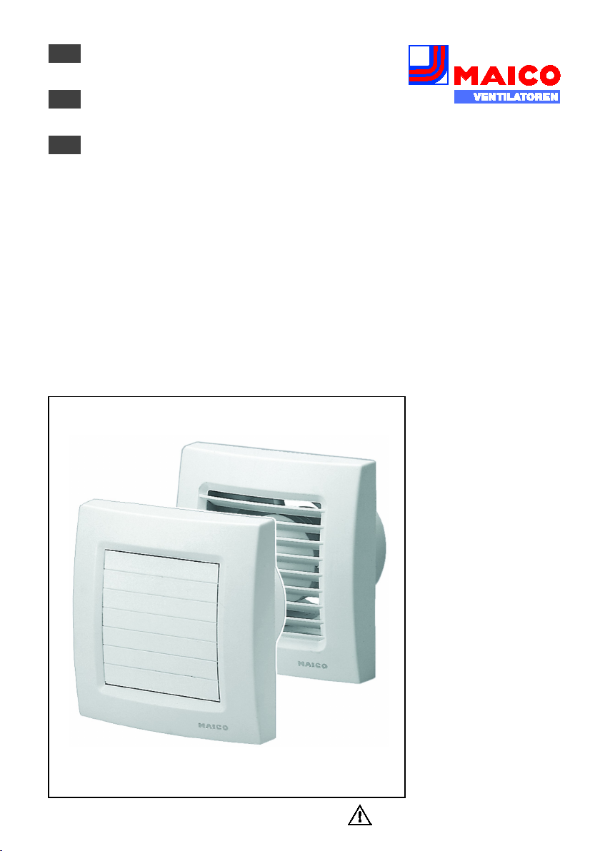
Montage- und Betriebsanleitung
www.maico- ventilatoren.com
DE
UK
FR
Kleinraumventilatoren
Mounting and Operating instructions
Small room fans
Instructions de montage et Mode d’emploi
Aérateurs pour petites pièces
ECA 120
ECA 120 K
Page 2

Montage- und
Betriebsanleitung
Seite 2
Schaltbilder
Seite 24
Lieferumfang
● Kleinraumventilator
ECA 120 oder ECA 120 K
● Montage- und
Betriebsanleitung
Zusätzliche
Informationen
Mit dem Smartphone direkt
zum Produkt. Im Internet unter
maico-ventilatoren.com.
Mounting an Operating
instructions
Page 9
Wiring diagrams
Page 24
Scope of delivery
● Small room fan
ECA 120 or ECA 120 K
● Mounting and operating
instructions
Instructions de montage et Mode d’emploi
Page 16
Schémas de
branchement
Page 24
Éléments fournis
● Aérateur pour petites
pièces ECA 120 ou
ECA 120 K
● Instructions de montage
et d'utilisation
Page 3
A
B
C
D
Page 4
DE │ Inhaltsverzeichnis
2
Lesen Sie diese Montage- und
Unmittelbar drohende Gefahr,
Möglicherweise gefährliche
Mögliche Situation, die zu
INFO-Symbol für wichtige Infor-
●
Aufzählungssymbol für Informa-
Handlungsanweisung. Führen
Impressum:
technische Änderungen vorbehalten.
Inhaltsverzeichnis
1. Allgemeine Hinweise ................................ 2
1.1 Installationspersonal.......................... 2
1.2 Verwendete Symbole ........................ 2
2. Produktinformationen ............................... 3
2.1 Geräteübersicht ................................. 3
2.2 Produktbeschreibung ........................ 3
2.3 Bestimmungsgemäße Verwendung... 3
2.4 Vorhersehbare Fehlanwendungen .... 4
3. Umgebungsbedingungen und Grenzen
für den Betrieb .......................................... 4
4. Technische Daten .................................... 4
5. Sicherheitshinweise ................................. 4
5.1 Allgemein .......................................... 4
5.2 Sicheres und korrektes Verhalten
für den Betrieb ........................................ 5
6. Montagevorbereitungen ........................... 5
6.1 Wand ................................................. 5
6.2 Decke ................................................ 5
6.3 Rohr .................................................. 6
6.4 Ventilator ........................................... 6
7. Montage ................................................... 6
7.1 Gehäuseeinbau ................................. 6
7.2 Elektrischer Anschluss ...................... 6
7.3 Inbetriebnahme ................................. 7
8. Wartung ................................................... 7
9. Reinigung ................................................. 7
10. Störungsbehebung ................................. 7
11. Ersatzteile .............................................. 8
12. Demontage............................................. 8
13. Entsorgung ............................................. 8
14. Schaltbilder .......................................... 24
1. Allgemeine Hinweise
Betriebsanleitung vor der ersten
Benutzung des Ventilators aufmerksam durch. Folgen Sie den
Anweisungen. Bewahren Sie diese
Anleitung für einen späteren
1.1 Installationspersonal
Die Montage ist nur durch Fachkräfte zulässig.
Der elektrische Anschluss darf nur von
Elektrofachkräften vorgenommen werden.
Diese besitzen eine elektrotechnische Ausbildung und das Wissen über die Gefahren
und Auswirkungen, die durch einen elektrischen Schlag erfolgen können.
1.2 Verwendete Symbole
Gebrauch gut auf.
GEFAHR
VORSICHT
ACHTUNG
1.
die bei Nichtbeachtung zu
schweren Körperverletzungen
oder zum Tod führt.
Situation, die zu leichten bis
mittleren Körperverletzungen
führen könnte.
Sachschäden am Produkt oder
seiner Umgebung führen könnte.
mationen und Tipps.
tionen zum jeweiligen Thema.
Sie die angegebenen Anweisungen der Reihe nach durch.
© Maico Elektroapparate-Fabrik GmbH. Deutsche
Original-Betriebsanleitung. Druckfehler, Irrtümer und
Page 5

2. Produktinformationen │ DE
3
F-Geräte können unabhängig von
2. Produktinformationen
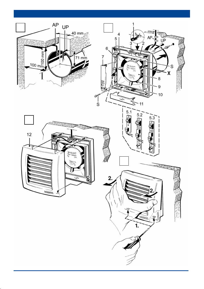
2.1 Geräteübersicht, Abb. B und C
1 Federhaken
2 Leitungstülle hinten
3 Leitungstülle oben
4 Gehäuse mit Motor
5 Elektronikplatine
5.1 Grundplatine (Standard, P, 24-V)
5.2 VZ-Platine
5.3 F-Platine
6 Klemmenleiste
7 Elektronikabdeckung (VZ, KVZ, F, KF)
8 Motorschutzdeckel
9 Flügelrad
10 ECA 120 K: Thermo-Bimetall
11 ECA 120 K: Bimetallabdeckung
12 Innengitter/Klappenrahmen
S Schraube (nicht im Lieferumfang)
2.2 Produktbeschreibung
● ECA 120 mit feststehendem Innengitter.
● ECA 120 K mit elektrisch betätigtem
Klappenrahmen.
Ausführungen
● Standardausführung: Bedienbar mit
bauseitig bereitzustellendem Schalter.
Gerät drehzahlsteuerbar.
● VZ-Ausführung mit Verzögerungszeit-
schalter. Bedienbar mit bauseitig bereitzustellendem Schalter. Einschaltverzögerung ca. 50 Sekunden und Nachlaufzeit
ca. 6 Minuten. Gerät nicht drehzahlsteuerbar.
● F-Ausführung mit Lichtsteuerung, Ein-
schaltverzögerung ca. 50 Sekunden und
Nachlaufzeit ca. 6 Minuten. Barrierefreie
Anwendung. Die Lichtsteuerung schaltet
den Ventilator automatisch ein und aus:
Einschalthelligkeit am Gerät min. 30 lx,
Ausschalthelligkeit am Gerät max. 0,3 lx.
Gerät nicht drehzahlsteuerbar.
der Beleuchtung per optionalem
Lichtschalter bedient werden. Bei
„Licht an“ startet die Automatik. Wird
das Licht ausgeschaltet, läuft das
Gerät weiter, bis die verbleibende
Nachlaufzeit abgelaufen ist.
● P-Ausführung: Mit Zugschnurschaltung.
Gerät nicht drehzahlsteuerbar.
● 24-V-Ausführung mit Sicherheitsklein-
spannung 24 V, 50 Hz. Bedienbar mit
optionalem Schalter. Kombination mit
Verzögerungszeitschalter VZ 6, VZ 12
oder VZ 24 C möglich (siehe Zubehör).
Gerät nicht drehzahlsteuerbar.
2.3 Bestimmungsgemäße
Verwendung
● ECA 120 und ECA 120 K sind Kleinraumventilatoren zum Entlüften von Räumen.
● Diese Geräte sind ausschließlich für den
Hausgebrauch und ähnliche Zwecke
vorgesehen.
● Die Geräte dienen zum Entlüften von
Bädern, WCs, Abstell- und Vorratsräumen,
Kellern, Einfamilienhäusern, Büros und
ähnlichen Räumen.
● Zulässig ist ein Betrieb nur bei:
● Festinstallation innerhalb von Gebäuden.
● Aufputzinstallation an Wand, Decke oder
Rohr.
● Luftführung über Schacht oder Rohr.
● elektrischem Festanschluss, Aufputz
oder Unterputz.
● mit ausreichendem Platz zur Wand und
Decke gemäß Abb. A.
● komplett montiertem Gerät.
● Der Betrieb der 24-V-Ausführung ist nur
mit zugelassenem Sicherheitstransformator TRE 50 (230 V/24 V) zulässig.
Verzögerungszeitschalter sind zwischen
Schalter (230 V) und Eingangsseite des
Sicherheitstransformators gemäß
Schaltbild einzubauen.
Page 6

DE │ 2. Produktinformationen
4
2.4 Vorhersehbare Fehlanwendungen
Maico haftet nicht für Schäden durch bestimmungswidrigen Gebrauch. Gerät auf keinen
Fall einsetzen:
● in Einzelentlüftungsanlagen nach
DIN 18017-3.
● in der Nähe von brennbaren Materialien,
Flüssigkeiten oder Gasen.
● für die Förderung von Chemikalien,
aggressiven Gasen oder Dämpfen.
● in explosionsfähiger Atmosphäre.
● im Außenbereich.
● wenn auf der Ausblasseite ein Berüh-
rungsschutz des Flügelrades nach
EN ISO 13857 fehlt.
3. Umgebungsbedingungen und
Grenzen für den Betrieb
● Zulässige Höchsttemperatur des Fördermediums + 40 °C.
● Die Luftführung in der Wohnung muss so
erfolgen, dass möglichst keine Luft aus
Küche, Bad und WC in die Wohnräume
überströmen kann.
● Ein zu entlüftender Raum muss mit
einem unverschließbaren, freien Zuluftquerschnitt von mindestens 150 cm²
ausgestattet sein, z. B. mit Türlüftungsgitter MLK.
● Bei Betrieb mit raumluftabhängigen
Feuerstätten muss für ausreichende
Zuluftnachströmung gesorgt werden.
Die maximal zulässige Druckdifferenz
pro Wohneinheit beträgt 4 Pa.
● VZ-, F-, KVZ- und KF-Geräte:
Störfestigkeit nach EN 55014-2 je nach
Impulsform und Energieanteil 1000 bis
4000 V. Bei Betrieb mit Leuchtstoffröhren
sind zusätzliche Entstörmaßnahmen
erforderlich (L-, C- oder RC-Glieder,
Schutzdioden, Varistoren), da diese
Werte überschritten werden können.
4. Technische Daten
Siehe Typenschild.
5. Sicherheitshinweise
5.1 Allgemein
● Lesen Sie diese Betriebsanleitung vor Montage und
Inbetriebnahme aufmerksam
durch.
● Die Montage und der elektrische Anschluss ist nur durch
Fachkräfte gemäß Kapitel 1
zulässig.
● Bei der Elektroinstallation und
Gerätemontage sind die einschlägigen Vorschriften, in
Deutschland besonders DIN
VDE 0100 mit den entsprechenden Teilen, zu beachten.
● Gerät nur an fest verlegte
elektrische Installation mit
Leitungen vom Typ NYM-O
oder NYM-J (2 x 1,5 mm² oder
3 x 1,5 mm²) anschließen.
Vorrichtung zur Trennung
vom Netz mit mind. 3 mm
Kontaktöffnung je Pol erforderlich.
● Gerät nur mit auf Typenschild
angegebener Spannung und
Frequenz betreiben.
● Gerät nur komplett montiert
betreiben.
● Vor Abnehmen von Innengitter/Klappenrahmen [8] Gerät
allpolig vom Netz trennen.
Page 7
5. Sicherheitshinweise │ DE
5
Vorgeschriebene Mindestabstände
Empfehlung: Wandhülse WH 120
Kurzschlussgefahr und
● Veränderungen und Umbauten am Gerät sind nicht
zulässig und entbinden den
Hersteller von jeglicher
Gewährleistung und Haftung.
5.2 Sicheres und korrektes
Verhalten für den Betrieb
Verletzungsgefahr bei Gegenständen im Flügelrad.
Keine Gegenstände in
das Gerät hineinstecken.
Verletzungsgefahr durch
sich drehendes Flügelrad.
Nicht zu nahe an das
Gerät gehen, damit
Haare, Kleidung oder
Schmuck nicht in das
Gerät hineingezogen
werden können.
● Dieses Gerät kann von Kindern
ab 8 Jahren und darüber
sowie von Personen mit
verringerten physischen,
sensorischen oder mentalen
Fähigkeiten oder Mangel an
Erfahrung und Wissen
benutzt werden, wenn sie
beaufsichtigt oder bezüglich
des sicheren Gebrauchs des
Gerätes unterwiesen wurden
und die daraus resultierenden
Gefahren verstehen.
Kinder dürfen nicht mit dem
Gerät spielen. Reinigung und
Benutzer-Wartung dürfen
nicht von Kindern ohne
Beaufsichtigung durchgeführt
werden.
6. Montagevorbereitungen
6.1 Wand
zur Wand und Decke gemäß Abb. A
einhalten.
1. Im Bereich des Gehäuses für einen
ebenen Untergrund sorgen.
2. Wanddurchbruch anbringen oder Kernloch
bohren: Mindestdurchmesser 120 mm.
einbauen. Wanddurchbruch mit
Mindestdurchmesser 136 mm
anbringen.
3. Netzleitung gemäß Abb. A bis an den
Montageort verlegen (Aufputz AP oder
Unterputz UP). Abstandsmaße beachten.
Leitungslänge innerhalb des Gehäuses
berücksichtigen.
6.2 Decke
ACHTUNG
Montagevorbereitungen wie in Kapitel 6.1
beschrieben vornehmen.
Gerätebeschädigung durch
Kondenswasserbildung im
Ventilatorgehäuse.
Lüftungsleitungen fachgerecht
thermisch isolieren. Kondenswasserableitung oder Kondensatsammler in der Steigleitung
einplanen.
Page 8
DE │ 6. Montagevorbereitungen
6
ACHTUNG
Beschädigung von flexiblen
Federhaken abbrechen.
Lebensgefahr durch Strom-
Warnschild sichtbar anbringen.
ACHTUNG
Gerätebeschädigung bei
Adern abschneiden und isolieren.
Öffnungsfunktion des Klap-
Adern abschneiden und isolieren.
ACHTUNG
Gerätebeschädigung durch
oder Kontaktflächen vermeiden.
6.3 Rohr
1. Kanten der Rohrinnenseite entgraten.
Rohren (Wickelfalzrohre)
durch Federhaken.
Vor Einbau in flexible Rohre die
2. Ggf. die beiden Federhaken [1] abbrechen
3. Montagevorbereitungen wie in Kapitel 6.1
beschrieben vornehmen.
6.4 Ventilator
1. Gerät auspacken.
2. Innengitter/Klappenrahmen [8] abnehmen.
Zum Lösen beide Schnapper ( Abb. D)
mit einem Schraubendreher entriegeln.
7. Montage
7.1 Gehäuseeinbau
1. Gehäuse [4] in Wanddurchbruch/Wandhülse/Rohr stecken.
2. Gehäuse [4] waagerecht ausrichten, die
beiden Dübellöcher markieren, Ø 6 mm
Dübellöcher bohren und Dübel einstecken.
ACHTUNG Kurzschlussgefahr und Geräte-
beschädigung. Bei falsch
eingeführter Netzleitung oder
nicht fachgerecht eingebauter
Leitungstülle kann Wasser in
das Ventilatorgehäuse eindringen und die Schutzart ist
nicht gewährleistet.
Die Leitungstülle [2] oder [3] so
durchstoßen, dass diese die
Netzleitung dicht umschließen
kann (rund ausschneiden, kein
Schlitz).
Auf- bzw. Unterputzleitungen
an der dafür vorgesehenen
Leitungstülle ordnungsgemäß
einführen.
3. Leitungstülle [2] oder [3] vorsichtig aus
dem Gehäuse [4] drücken, herausnehmen
und mit einem Tüllenstecher kreisrund
durchstoßen. Für Aufputzinstallation
Leitungstülle [3], für Unterputzinstallation
Leitungstülle [2] verwenden.
4. Die ausgebaute Leitungstülle fachgerecht
in das Gehäuse einsetzen, diese ggf.
bauseitig abdichten.
5. Netzleitung so in den Anschlussraum
führen, dass die Leitungstülle den
Leitungsmantel komplett umschließt.
7.2 Elektrischer Anschluss
schlag.
GEFAHR
Vor Zugang zu den Anschlussklemmen alle Versorgungsstromkreise abschalten. Netzsicherung
ausschalten, gegen Wiedereinschalten sichern und ein
Kurzschluss.
Schutzleiter und nicht benötigte
ACHTUNG
penrahmens (K-Ventilatoren)
wird durch überstehende
Leitungen behindert.
Schutzleiter und nicht benötigte
Berühren ESD-gefährdeter
Bauteile auf Platine [5.2] / [5.3].
Direktes Berühren der Bauteile
1. Netzsicherung ausschalten.
2. Im Gerät nur Einzeladern verlegen. Mantel
der Netzleitung entfernen und Ader-Enden
abisolieren.
Page 9

7
Gehäuse weder verspannt noch
Lebensgefahr durch Strom-
Warnschild sichtbar anbringen.
ACHTUNG
Gerätebeschädigung bei
verwenden.
Bei ECA 120 K: Lamellenbruch
oder verbiegen.
Bei jeder Störung eine Elektrofach-
nur durch Elektrofachkräfte zulässig.
Lebensgefahr durch Strom-
Warnschild sichtbar anbringen.
3. Gehäuse [4] in Wand/Decke/Rohr einsetzen und mit 2 Schrauben [S] befestigen.
gequetscht einsetzen. Ausreichend
dimensioniertes Befestigungsmaterial ist bauseitig bereitzustellen.
4. Netzleitung an Klemmenleiste [6] gemäß
Schaltbild in Kapitel 14 verdrahten (je
nach Ausführung 2- oder 3-adrig). Bei
Aufputzanschluss „AP“ die Zugentlastung
verwenden und diese mit beiden Schrauben [13] verschrauben.
5. Sitz der Leitungstülle [2] und [3] kontrollieren. Diese müssen gut abdichten.
6. VZ- und F-Geräte: Elektronikabdeckung
[7] aufstecken ( Abb. B).
7. Innengitter/Klappenrahmen [8] gleichmäßig auf Gehäuse [4] drücken, bis
dieses/dieser in die beiden Schnapper
einrastet ( Abb. D). Nicht verkanten.
7.3 Inbetriebnahme
1. Netzsicherung einschalten.
2. Funktionstest durchführen.
8. Wartung
Das Gerät ist wartungsfrei.
7. Montage ‒ Elektrischer Anschluss │ DE
9. Reinigung
schlag.
GEFAHR
Vor Zugang zu den Anschlussklemmen alle Versorgungsstromkreise abschalten. Netzsicherung
ausschalten, gegen Wiedereinschalten sichern und ein
falschem Reinigungsmittel.
Innengitter/Klappenrahmen [8]
nur mit Wasser reinigen. Keine
aggressiven Reinigungsmittel
ACHTUNG
bei falschem Reinigen.
Vorsicht beim Reinigen. Lamellen
nicht zu stark öffnen, schließen
1. Netzsicherung ausschalten.
2. Ventilator bei Verschmutzung mit einem
angefeuchteten Tuch reinigen.
3. Bei stark verunreinigtem Innengitter/Klappenrahmen [8] dieses(n) vorsichtig abnehmen ( Abb. D) und mit Wasser reinigen.
4. Innengitter/Klappenrahmen anbringen.
5. Netzsicherung einschalten. Funktionstest
durchführen.
10. Störungsbehebung
kraft hinzuziehen. Reparaturen sind
schlag.
GEFAHR
Vor Zugang zu den Anschlussklemmen alle Versorgungsstromkreise abschalten. Netzsicherung
ausschalten, gegen Wiedereinschalten sichern und ein
Page 10

DE │ 10. Störungsbehebung
8
Störung
Ursache, Maßnahme
Ventilator
nicht ein.
VZ- oder F-Geräte:
50 Sekunden) abwarten.
Ventilator
Keine Netzspannung.
ist. Diese ggf. einschalten.
Ventilator
Laufrad blockiert.
ggf. reinigen.
Ventilator
nicht aus.
VZ- oder F-Geräte:
abwarten.
Thermischer
aus.
Motor zu heiß. Warten, bis
selbsttätig wieder ein.
Bei K-Geräten
Lamellen stark verschmutzt
beseitigen.
Bezug und Einbau der Ersatzteile
Pos.
Bezeichnung
Artikel-Nr.
5.1
Grundplatine:
Standard, 24-V, K
F101.1010.9000
5.2
VZ-Platine: Gerätetypen VZ + KVZ
0101.1257.0000
5.3
F-Platine: Gerätetypen F + KF
0101.1255.0000
10
ECA 120 K:
Thermo-Bimetall
E180.0913.9100
12
ECA 120:
Klappenrahmen
0059.1010.9000
Die Demontage darf nur von einer
vorgenommen werden.
Lebensgefahr durch Strom-
Warnschild sichtbar anbringen.
Verbrennungsgefahr durch
betragen.
Nicht in den Restmüll. Das Gerät
schaltet
schaltet
nicht ein.
schaltet
nicht ein.
schaltet
Überlastungsschutz des
Motors schaltet
den Ventilator
öffnen oder
schließen die
Lamellen nicht.
Einschaltverzögerung (ca.
Prüfen, ob die
Netzsicherung ausgefallen
Nur durch Fachkraft
zulässig: Innengitter/Klap-
penrahmen [8] entriegeln
und abnehmen ( Abb. D).
Flügelrad überprüfen und
Nachlaufzeit (ca. 6 Minuten)
der Motor abgekühlt ist. Die
Abkühlzeit kann bis zu
10 Minuten betragen. Gerät
schaltet nach Abkühlung
oder blockiert.
Lamellen reinigen.
Prüfen, ob sich Gegenstände zwischen den Lamellen
befinden. Diese ggf.
11. Ersatzteile
nur durch den Fachinstallateur.
Gerätetypen
Bei Rückfragen
Maico Elektroapparate-Fabrik GmbH
Steinbeisstraße 20
78056 Villingen-Schwenningen, Deutschland
Tel. +49 7720 694 445 / Fax +49 7720 694 175
E-Mail: ersatzteilservice@maico.de
12. Demontage
Elektrofachkraft ( Kapitel 1)
schlag.
GEFAHR
VORSICHT
1. Netzsicherung ausschalten.
2. Innengitter/Klappenrahmen [8] entriegeln
( Abb. D) und abnehmen.
3. Elektronikabdeckung [7] entfernen, Netzleitung entfernen.
4. Ventilator ausbauen. Dazu mit einem
Schraubendreher beide Rasthaken [1]
aus der Rastung drücken und den
Ventilator gleichmäßig abziehen.
Vor Zugang zu den Anschlussklemmen alle Versorgungsstromkreise abschalten. Netzsicherung
ausschalten, gegen Wiedereinschalten sichern und ein
Berühren des Bimetalls [10]
(K-Geräte).
Bimetall [10] nicht anfassen.
Bimetall ist nach Ausschalten
des Ventilators sehr heiß. Die
Abkühlzeit kann bis zu 10 Minuten
Innengitter
ECA 120 K:
0059.1011.9001
13. Entsorgung
enthält teils wiederverwertbare
Stoffe, teils Substanzen, die nicht in
den Restmüll gelangen dürfen.
Das Gerät ist nach Ablauf seiner Lebensdauer nach den in Ihrem Land geltenden
Bestimmungen zu entsorgen.
Page 11

Table of contents │ UK
9
Read these mounting and
Direct risk of danger. Failure to
Possibly dangerous situation
NOTICE
Possible situation which could
INFO symbol indicating impor-
●
Bullet point for information on the
Instructions. Follow the instruct-
Acknowledgements:
technical modifications without giving prior notice.
Table of contents
1. General notes .......................................... 9
1.1 Installation staff ................................. 9
1.2 Symbols used ................................... 9
2. Product information ................................ 10
2.1 Unit overview .................................. 10
2.2 Product description ......................... 10
2.3 Intended use ................................... 10
2.4 Foreseeable cases of misuse .......... 11
3. Environmental conditions and
operating limits ....................................... 11
4. Technical data ........................................ 11
5. Safety instructions .................................. 11
5.1 General ........................................... 11
5.2 Safe and correct practices during
operation ............................................... 12
6. Installation preparations ......................... 12
6.1 Wall ................................................. 12
6.2 Ceiling ............................................. 12
6.3 Duct ................................................ 13
6.4 Fan.................................................. 13
7. Installation .............................................. 13
7.1 Installing housing ............................ 13
7.2 Electrical connection ....................... 13
7.3 Commissioning ............................... 14
8. Maintenance .......................................... 14
9. Cleaning ................................................. 14
10. Fault rectification .................................. 14
11. Spare parts .......................................... 15
12. Dismantling .......................................... 15
13. Disposal ............................................... 15
14. Wiring diagrams ................................... 24
© Maico Elektroapparate-Fabrik GmbH. English
translation from the original German Operating
Instructions. We cannot be held responsible for
mistakes or printing errors and retain the right to make
1. General notes
operating instructions carefully
before using the fan for the first
time. Follow the instructions. Keep
these instructions safe for use later
on.
1.1 Installation staff
Installation is only permitted when carried out
by trained specialists.
Only qualified electricians are permitted to
make the electrical connections. Installation
staff are trained in electrical engineering and
are aware of the risks and consequences of
an electric shock.
1.2 Symbols used
observe will result in severe
DANGER
CAUTION
1.
injury or death.
which could result in minor to
moderate injuries.
cause damage to the product or
its surroundings.
tant information and tips.
corresponding subject.
tions given in the order stated.
Page 12

UK │ 2. Product information
10
F units can be operated indepen-
2. Product information
2.1 Unit overview, Fig. A, B and C
1 Spring hook
2 Cable grommet, rear
3 Cable grommet, top
4 Housing with motor
5 Electronic circuit board
5.1 Mother board (Standard, P, 24-V)
5.2 VZ circuit board
5.3 F circuit board
6 Terminal block
7 Electronics cover (VZ, KVZ, F, KF)
8 Motor protection cover
9 Impeller
10 ECA 120 K: Thermostatic bimetal strip
11 ECA 120 K: Bimetal cover
12 Internal grille / shutter frame
S Screw (not included in scope of delivery)
2.2 Product description
● ECA 120 with fixed internal grille.
● ECA 120 with electrically operated shutter
frame.
Models
● Standard model: Can be operated with
switch which is to be provided by the
customer. Unit, speed controllable.
● Model VZ with time delay switch. Can be
operated with switch which is to be
provided by the customer. Adjustable start
delay approx. 50 seconds and overrun
time approx. 6 minutes. Unit, not speed
controllable.
● Model F with light control, adjustable start
delay approx. 50 seconds and overrun
time approx. 6 minutes. Barrier-free
application. The light control switches the
fan automatically on and off: Switch-on
intensity at fan min. 30 lx, switch-off
intensity at fan max. 0.3 lx. Unit, not
speed controllable.
dently of the lighting using the
optional light switch. The automatic
operating mode commences when
"Light on". If the light is switched off,
the unit continues to run until the
remaining overrun time has passed.
● Model P: With pull-cord switch.
Unit, not speed controllable.
● 24 V model with safety extra-low voltage
24 V, 50 Hz. Can be operated with
optional switch. Can be combined with
time delay switch VZ 6, VZ 12 or VZ 24 C
(see accessories). Unit, not speed
controllable.
2.3 Intended use
● ECA 120 and ECA 120 K are small room
fans for extracting air from rooms.
● These fan units are only intended for
domestic use and similar purposes.
● The fan units are used to extract air from
bathrooms, WCs, storage rooms, cellars,
single family-unit houses, offices and
similar places.
● Operation is only permitted when:
● fixed installation within buildings.
● surface installation on walls, ceilings
or ducts.
● air supply via shaft or duct.
● permanent electrical connection,
surface-mounted or recessed-mounted.
● with sufficient space from the wall or
ceiling as shown in Fig. A.
● unit is completely installed.
● The operation of the 24 V model is only
permitted with approved safety isolating
transformer TRE 50 (230 V/24 V). The
time delay switches are to be installed
between switch (230 V) and input side of
the safety isolating transformer in
accordance with the wiring diagram.
Page 13

2. Product information │ UK
11
2.4 Foreseeable cases of misuse
Maico is not liable for damages caused
by usage other than its intended purpose.
The fan unit should not be used:
● in single air extraction systems according
to DIN 18017-3.
● close to flammable materials, liquids or
gases.
● to convey chemicals, aggressive gases
or vapours.
● in potentially explosive atmospheres.
● outdoors
● if there is no protection against accidental
contact with the impeller on the discharge
side in accordance with EN ISO 13857.
3. Environmental conditions and
operating limits
● Permissible maximum temperature of air
medium + 40 °C.
● The domestic air supply must be set up so
that virtually no air can flow into the living
areas from the kitchen, bathroom and WC.
● A room from which the air has to be extracted must be fitted with a non-closable,
free supply air cross section of at least
150 cm²,e.g. with Maico door ventilation
grille MLK.
● Sufficient supply air intake must be ensured during operation with air-ventilated
fireplaces. The maximum permitted
pressure difference per living unit is 4 Pa.
● VZ, F, KVZ and KF units: Resistance to
interference according to EN 55014-2
depending on pulse shape and energy
component 1000 to 4000 V. If operating
with fluorescent tubes, extra interference
suppression measures are needed (L or
C components or RC modules, protection
diodes, varistors) because these values
may be exceeded.
5. Safety instructions
5.1 General
● Read these operating instructions carefully before mounting and commissioning.
● Assembly and electrical connection may only be undertaken by trained specialists in
accordance with Chapter 1.
● With electrical and equipment
installation the relevant
regulations must be observed,
in Germany particularly DIN
VDE 0100 with the corresponding parts.
● Only connect unit to permanently wired electrical installations with NYM-O or NYM-J
(2 x 1.5 mm² or 3 x 1.5 mm²)
cables. Mains isolation device
required with contact
openings of at least 3 mm at
each pole.
● The fan unit may only be
operated using the voltage
and frequency shown on the
rating plate.
● Only operate the fan unit
when it is completely
installed.
4. Technical data
See rating plate.
Page 14

UK │ 5. Safety instructions
12
The prescribed minimum distances
Recommendation: Fit wall sleeve
Danger of short-circuits and
riser.
● Disconnect (all poles) the unit
completely from the power
supply before removing the
internal grille/shutter frame [8].
● Modifications and alterations
to the fan unit are not
permitted and release the
manufacturer from any
guarantee obligations and
liability.
5.2 Safe and correct practices
during operation
Danger of injury caused
by objects in the rotating
impeller. Do not insert any
objects in the fan unit.
Danger of injury from
rotating impeller. Do not
get too close to the fan
unit, to avoid hair,
clothing or jewellery being
drawn into the unit.
● This fan unit can be used by
children aged 8 and above,
and by people with reduced
physical, sensory or mental
capabilities or by persons with
insufficient experience or
knowledge provided they are
supervised by a person
responsible for their safety,
or they have been instructed
about the safe operation of
the unit and can understand
the resulting risks thereof.
Children must not play with
the unit. Cleaning and
maintenance must not be
carried out by children without
supervision.
6. Installation preparations
6.1 Wall
from wall and ceiling as shown in
Fig. A must be observed.
1. Make sure the housing has a level base.
2. Fit wall breakthrough or drill core hole:
minimum diameter, 120 mm.
WH 120. Fit wall breakthrough with
minimum diameter 136 mm.
3. Lay the power cable as shown in Fig. A up
to place of installation (surface-mounted
AP or recessed-mounted UP). Observe
spacing. Observe ducting length within the
housing.
6.2 Ceiling
NOTICE
Perform installation preparations as
described in Chapter 6.1.
damage to unit if condensation builds up in the fan
housing.
Thermally insulate ventilation
ducts in professional manner.
Allow for a condensation drain
or condensate collector in the
Page 15

6. Installation preparations │ UK
13
Risk of damage to flexible
to installation of the flexible ducts.
Danger to life from electric
visible warning sign.
Risk of damage to unit in the
are not required!
The opening function of the
are not required!
Risk of damage to the unit if
components or contact surfaces.
6.3 Duct
1. Debur edges on the inside of the duct.
NOTICE
ducts (folded spiral-seams
ducts) caused by spring hooks.
Snap off the spring hooks prior
2. If necessary snap off the two spring
hooks [1].
3. Perform installation preparations as
described in Chapter 6.1.
6.4 Fan
1. Unpack fan unit.
2. Remove internal grille/shutter frame [8].
For loosening unlock both safety catches
( Fig. D) with a screwdriver.
7. Installation
7.1 Installing housing
1. Insert housing [4] in wall breakthrough/wall
sleeve/duct.
2. Align housing [4] horizontally, mark the
two dowel holes, drill the dowel holes Ø 6
mm and insert the dowels.
NOTICE Danger of short circuits and
damage to unit. If the power
cable is incorrectly fed or if
the cable grommet is not fitted
correctly, water may penetrate
into the fan housing and the
degree of protection cannot
be guaranteed.
Pierce the cable grommet [2] or
[3] such that the cable grommet
tightly clasps the power cable
(cut in a round shape, no slot).
Guide the surface- or recessedmounted cables correctly into
the intended cable grommet.
3. Carefully press out the cable grommet [2]
or [3] from the housing [4], then remove
and pierce a round hole in the cable
grommet by means of a grommet puncher.
Use cable grommet [3] for surface
installation and cable grommet [2] for
recess installation.
4. Reinsert the removed cable grommet in
a professional manner, provide sealing
on site if necessary.
5. Guide the power cable into the connection
area such that the cable grommet fits
around the cable sheathing completely.
7.2 Electrical connection
shock.
DANGER
Prior to access to the connection
terminals switch off all supply
circuits. Switch off main fuses,
secure against being accidentally
switched back on and position a
NOTICE
event of short-circuits.
Cut off and insulate PE conductor
and individual cable cores that
NOTICE
shutter frame (K fans) will be
hindered by protruding cables!
Cut off and insulate PE conductor
and individual cable cores that
NOTICE
ESD sensitive components on
the board are touched [5.2] /
[5.3].
Avoid direct touching of the
1. Switch the mains fuse off.
2. Only lay single cable cores in the unit.
Remove the power cable cladding and
insulate the ends of the cable cores.
Page 16

UK │ 7. Installation - Electrical connection
14
Do not insert the housing such that it
Danger to life from electric
visible warning sign.
Risk of damage to unit if incur-
agents.
In the case of ECA 120 K:
shutting or bending the lamella.
Call on the services of a trained
Danger to life from electric
visible warning sign.
3. Insert housing [4] into wall/ceiling/duct and
secure with two screws [S].
is twisted or crushed. Sufficiently
dimensioned mounting material is to
be supplied by the customer.
4. Wire the power cable to the terminal block
[6] in accordance with the wiring diagram
in Chapter 14 (2- or 3-core, depending on
the version). In the case of surfacemounted connection "AP", use the tension
relief and screw this into place with both
screws [13].
5. Check position of cable grommets [2] and
[3]. These must provide a good seal.
6. VZ and F units: Plug the electronics cover
[7] into place ( Fig. B).
7. Apply equal pressure to press the internal
grille/shutter frame [8] onto the housing [4]
until it clicks into place onto the two safety
catches ( Fig. D). Do not twist it.
7.3 Commissioning
1. Switch the mains fuse on.
2. Carry out a function test.
8. Maintenance
The unit is maintenance-free.
9. Cleaning
shock.
DANGER
Prior to access to the connection
terminals switch off all supply
circuits. Switch off main fuses,
secure against being accidentally
switched back on and position a
NOTICE
rect cleaning agent is used!
Only clean the internal
grille/shutter frame [8] with water.
Do not use aggressive cleaning
NOTICE
Lamella may break if cleaned
incorrectly.
Take care when cleaning. Do not
exercise force when opening,
1. Switch the mains fuse off.
2. If dirty, clean the fan with a damp cloth.
3. If the internal grille/shutter frame [8] is very
dirty, carefully remove it ( Fig. D) and
clean it with water.
4. Refit the internal grille/shutter frame.
5. Switch the mains fuse on. Carry out a
function test.
10. Fault rectification
electrician any time there is a fault.
Repairs should only be carried out by
a trained electrician.
shock.
DANGER
Prior to access to the connection
terminals switch off all supply
circuits. Switch off main fuses,
secure against being accidentally
switched back on and position a
Page 17

15
Fault
Cause / measure
Fan does not
switch on.
VZ or F units: Wait for start
delay (approx. 50 seconds).
Fan does not
switch on.
No mains voltage.
necessary.
Fan does not
Impeller blocked.
ler and clean if necessary.
Fan does not
VZ or F units: Wait for
6 minutes).
Motor's thermal
the fan
Motor too hot. Wait until
cooling.
Lamella do not
Lamella very dirty or
Remove if necessary.
Item
Designation
Article no.
5.1
Mother board:
types, 24-V, K
F101.1010.9000
5.2
VZ circuit board:
types
0101.1257.0000
5.3
F circuit board: F
+ KF device types
0101.1255.0000
10
ECA 120 K:
bimetal strip
E180.0913.9100
12
ECA 120:
Shutter frame
0059.1010.9000
Dismantling may only be undertaken
Danger to life from electric
visible warning sign.
Danger of burning due to
can be up to 10 minutes.
Not in domestic waste. The unit
Check whether the mains
fuse has failed. Switch on if
10. Fault rectification │ UK
In the case of questions:
Maico Elektroapparate-Fabrik GmbH
Steinbeisstraße 20
78056 Villingen-Schwenningen, Germany
Tel. +49 7720 694 445 / Fax +49 7720 694 175
E-Mail: ersatzteilservice@maico.de
switch on.
switch off.
overload
protection
switches
off.
open or close
for K units.
Should only be carried
out by a trained electrician: Unlock and remove the
internal grille/ shutter frame
[8] ( Fig. D). Check impel-
overrun time (approx.
the motor has cooled. Cooldown time can be up to
10 minutes. Unit switches
back on automatically after
blocked.
Clean lamella.
Check whether there is anything between the lamella.
11. Spare parts
Spare parts may only be sourced from
and fitted by a specialist installer.
Standard device
VZ + KVZ device
12. Dismantling
by a trained electrician ( Chapter 1).
shock.
DANGER
Prior to access to the connection
terminals switch off all supply
circuits. Switch off main fuses,
secure against being accidentally
switched back on and position a
contact with bimetal strip [10]
CAUTION
(K units).
Do not touch bimetal strip [10].
Bimetal strip is very hot after fan
is switched off. Cool-down time
1. Switch the mains fuse off.
2. Unlock and remove the internal
grille/shutter frame [8] ( Fig. D).
3. Remove electronics cover [7], remove
power cable.
4. Remove fan. To do this, press both locking
hooks [1] out of their latched positions
using a screwdriver and pull the fan out
by pulling with equal force on both sides.
13. Disposal
Thermostatic
internal grille
ECA 120 K:
0059.1011.9001
contains in part material that can be
recycled and in part substances that
should not end up as domestic
waste.
Dispose of the unit once it has reached the
end of its working life according to the
regulations valid where you are.
Page 18

FR │ Sommaire
16
Lisez attentivement les instructions
Danger immédiat qui, s'il n'est
Situation vraisemblablement
ATTENTION
Situation pouvant entraîner des
Symbole INFO pour informations
●
Symbole d'énumération
Marche à suivre. Suivez les
Mentions légales :
d'erreurs et de modifications techniques
Sommaire
1. Remarques générales ............................ 16
1.1 Installateurs ..................................... 16
1.2 Verwendete Symbole ...................... 16
2. Informations produit ............................... 17
2.1 Vue d'ensemble de l'appareil ........... 17
2.2 Description du produit ..................... 17
2.3 Utilisation conforme ......................... 17
2.4 Erreurs d'application prévisibles ...... 18
3. Conditions ambiantes et limites
d'utilisation ............................................. 18
4. Caractéristiques techniques ................... 18
5. Consignes de sécurité ............................ 18
5.1 Généralités ...................................... 18
5.2 Comportement sûr et correct lors
du fonction-nement ............................... 19
6. Préparatifs de montage .......................... 20
6.1 Mur .................................................. 20
6.2 Plafond ............................................ 20
6.3 Gaine .............................................. 20
6.4 Ventilateur ....................................... 20
7. Montage ................................................. 20
7.1 Montage du boîtier .......................... 20
7.2 Branchement électrique .................. 21
7.3 Mise en service ............................... 21
8. Entretien ................................................. 21
9. Nettoyage ............................................... 22
10. Élimination des dysfonctionnements .... 22
11. Pièces de rechange.............................. 23
12. Démontage........................................... 23
13. Élimination ........................................... 23
14. Schémas de branchement ................... 24
1. Remarques générales
de montage et le mode d'emploi
avant la première utilisation du
ventilateur. Respectez les instructions. Conservez ces instructions
1.1 Installateurs
Le montage est exclusivement réservé à des
professionnels.
Le branchement électrique doit exclusivement être réalisé par un électricien qualifié.
Les installateurs doivent avoir une formation
électrotechnique et connaître les dangers et
les effets d'un choc électrique.
1.2 Verwendete Symbole
pour une utilisation ultérieure.
pas pris en compte, entraîne de
DANGER
PRUDENCE
© Maico Elektroapparate-Fabrik GmbH. Traduction de
la notice d'origine. Sous réserve de fautes d'impression,
graves blessures corporelles ou
la mort.
dangereuse pouvant entraîner
des blessures corporelles de
gravité faible à moyenne.
dommages matériels du produit
ou de son environnement.
et conseils importants.
signalant des informations
relatives au sujet correspondant.
1.
instructions dans l'ordre indiqué.
Page 19

2. Informations produit │ FR
17
Les appareils F peuvent être com-
2. Informations produit
2.1 Vue d'ensemble de l'appareil,
fig. B et C
1 Mousqueton
2 Manchon de câble arrière
3 Manchon de câble haut
4 Boîtier avec moteur
5 Platine électronique
5.1 Platine de base (standard, P, 24 V)
5.2 Platine VZ
5.3 Platine F
6 Réglette de bornier
7 Capot de protection des unités
électroniques (VZ, KVZ, F, KF)
8 Couvercle de protection moteur
9 Hélice
10 ECA 120 K : Thermocouple bimétallique
11 ECA 120 K : Cache bimétallique
12 Grille intérieure/cadre de volet
S Vis (non fournie)
2.2 Description du produit
● ECA 120 avec grille intérieure fixe.
● ECA 120 K avec avec cadre de volet à
commande électrique.
Versions
● Version standard : Commandée par
interrupteur à fournir par le client. Appareil
à vitesse variable.
● Version VZ avec interrupteur-tempori-
sateur. Commandée par interrupteur à
fournir par le client. Temporisation de
démarrage env. 50 secondes et durée de
fonctionnement par inertie env. 6 minutes.
Appareil à vitesse non variable
● Version F avec commande
photoélectrique, temporisation de
démarrage env. 50 secondes et durée de
fonctionnement par inertie env. 6 minutes.
Utilisation adaptée aux personnes
handicapées.
La commande photoélectrique active et
désactive automatiquement le ventilateur.
Luminosité de mise en marche sur
l'appareil au minimum 30 lx, luminosité
d'arrêt sur l'appareil au maximum 0,3 lx.
Appareil à vitesse non variable
mandés par interrupteur d'éclairage
optionnel, indépendamment de
l'éclairage. Le mode automatique
démarre avec « Lumière allumée ».
Si la lumière est éteinte, l'appareil
continue à fonctionner jusqu'à la fin
du temps de fonctionnement par
inertie résiduel.
● Version P : avec interrupteur à tirette.
Appareil à vitesse non variable
● Version 24 V avec basse tension de
protection 24 V, 50 Hz. Commande par
interrupteur optionnel. Combinaison
possible avec interrupteur-temporisateur
VZ 6, VZ 12 ou VZ 24 C (voir accessoires). Appareil à vitesse non variable.
2.3 Utilisation conforme
● ECA 120 et ECA 120 K sont des
ventilateurs pour locaux de petites
dimensions servant à la ventilation des
pièces.
● Ces appareils sont exclusivement
réservés aux usages domestiques et
similaires.
● Ces appareils servent à ventiler les salles
de bain, les toilettes, les cagibis et
débarras, les caves, les maisons
individuelles, les bureaux et locaux
similaires.
● Le fonctionnement de la version 24 V
est autorisé uniquement avec le
transformateur de sécurité homologué
TRE 50 (230 V/24 V). Monter les
interrupteurs-temporisateurs entre
l'interrupteur (230 V) et l'entrée du
transformateur de sécurité selon le
schéma de branchement.
Page 20

FR │ 2. Informations produit
18
● Le fonctionnement est uniquement
autorisé aux conditions suivantes :
● Installation fixe à l'intérieur d'un
bâtiment.
● Installation apparente au mur, plafond,
gaine ronde.
● Circulation de l'air par gaine
rectangulaire ou ronde.
● Branchement électrique fixe, montage
apparent ou encastré.
● Distance suffisante par rapport au mur
et au plafond selon fig. A.
● Appareil entièrement assemblé.
2.4 Erreurs d'application prévisibles
Maico décline toute responsabilité en cas de
dommages découlant d'une utilisation nonconforme. Ne jamais utiliser l’appareil :
● dans des installations individuelles
d'extraction d'air selon la norme
DIN 18017-3.
● à proximité de matériaux, liquides ou gaz
inflammables.
● pour l'acheminement de produits
chimiques, de gaz ou de vapeurs
agressifs.
● dans des atmosphères explosives.
● à l'extérieur.
● en l'absence de protection de l'hélice
contre les contacts selon EN ISO 13857
du côté soufflage.
3. Conditions ambiantes et limites
d'utilisation
● Température maximale admise pour le
fluide refoulé + 40 °C.
● La circulation de l'air à l'intérieur du
logement doit être réalisée de telle
manière que l'air en provenance de la
cuisine, de la salle de bains et des toilettes
ne puisse pas se propager dans les pièces
d'habitation.
● La pièce à ventiler doit être équipée d'une
section d'air entrant impossible à verrouiller et libre d'au moins 150 cm², p. ex.
d'une grille de ventilation de porte MLK.
● Lors d'une utilisation avec des foyers
dépendants de l'air ambiant, il faut veiller
à une arrivée d'air suffisante.
La différence de pression maximale par
unité d'habitation est de 4 Pa.
● Appareils VZ, F, KVZ et KF :
Résistance aux interférences conforme
à la norme EN 55014-2 en fonction de la
forme de l'impulsion et de la proportion
d'énergie 1000 à 4000 V. En cas de
fonctionnement avec tubes fluorescents,
des mesures d'antiparasitage
supplémentaires sont nécessaires
(composants L, C ou RC, diodes de
protection, varistors), ces valeurs risquant
d'être dépassées.
4. Caractéristiques techniques
Voir plaque signalétique.
5. Consignes de sécurité
5.1 Généralités
● Avant le montage et la mise
en service, prière de lire
attentivement le présent
Mode d'emploi.
● Montage et branchement
électrique doivent
exclusivement être effectués
par des spécialistes selon les
instructions du Chapitre 1.
Page 21

5. Consignes de sécurité │ FR
19
● Lors de l'installation électrique
et du montage de l'appareil, il
convient de respecter les
directives en vigueur. En
Allemagne, il s'agit essentiellement de la norme DIN
VDE 0100 avec les parties
correspondantes.
● Brancher exclusivement
l'appareil sur une installation
électrique permanente avec
des câbles de type NYM-O
ou NYM-J (2 x 1,5 mm² ou
3 x 1,5 mm²). Dispositif de
déconnexion du secteur avec
au moins 3 mm d'ouverture
de contact par pôle.
● Utiliser exclusivement
l'appareil à la tension et à la
fréquence indiquées sur la
plaque signalétique.
● N'utiliser l'appareil qu'après
son montage complet.
● Avant d'enlever la grille
intérieure/le cadre de volet
[8], couper l'appareil du
secteur sur tous les pôles.
● Les modifications et
transformations apportées sur
l'appareil sont rigoureusement
interdites et dégagent le
fabricant de toute
responsabilité et garantie.
5.2 Comportement sûr et
correct lors du fonctionnement
Risque de blessure en
présence d'objets dans le
rotor. Ne jamais enfoncer
d'objet dans l’appareil.
Risque de blessure par
rotation de l'hélice. Ne
pas s'approcher trop près
de l'appareil afin d'éviter
que les cheveux, les
vêtements ou les bijoux
ne soient happés.
● Cet appareil peut être utilisé
par des enfants de 8 ans et
plus, ainsi que par des personnes à capacités physiques, sensorielles ou mentales amoindries, ou encore
manquant d'expérience et de
connaissances, dans la mesure où elles sont surveillées,
ont reçu les instructions
nécessaires à un emploi en
toute sécurité de l'appareil, et
ont été mises en garde contre
les dangers qu'il représente.
Les enfants ne doivent pas
jouer avec l'appareil. Les
enfants sans surveillance ne
doivent pas nettoyer l'appareil
ou procéder à des travaux
d'entretien revenant à
l'utilisateur.
Page 22

FR │ 6. Préparatifs de montage
20
Respecter les distances minimum
Recommandation : utiliser une gaine
minimum de 136 mm dans la paroi.
Risque de court-circuit et
colonne montante.
6. Préparatifs de montage
6.1 Mur
prescrites par rapport au mur et au
plafond selon la fig. A.
1. Assurer un support plan au niveau du boîtier.
2. Pratiquer un perçage de cloison ou percer
un avant-trou : diamètre minimal 120 mm.
murale WH 120. Pratiquer un
perçage de cloison d'un diamètre
3. Poser le câble secteur selon la fig. A
jusqu'au site de montage (montage
apparent AP ou montage encastré UP).
Respecter les écarts. Tenir compte de la
longueur des câbles dans le boîtier.
6.2 Plafond
ATTENTION
Effectuer les préparatifs de montage comme
décrit au Chapitre 6.1.
6.3 Gaine
1. Ébarber les bords de l'intérieur de la gaine.
ATTENTION Risque d'endommagement
d'endommagement de l'appareil résultant de la formation
d'eau de condensation dans
le boîtier du ventilateur.
Effectuer une isolation
thermique des gaines d'air
dans les règles de l'art. Prévoir
une évacuation de l'eau de
condensation ou un collecteur
de condensation dans la
des gaines souples (tuyaux
agrafés) par les crochets à
ressort.
Avant le montage dans les
gaines souples, rompre les
mousquetons.
2. Le cas échéant, rompre les deux
mousquetons [1].
3. Effectuer les préparatifs de montage
comme décrit au Chapitre 6.1.
6.4 Ventilateur
1. Déballer l'appareil.
2. Déposer la grille intérieure/le cadre de
volet [8]. Pour ce faire, déverrouiller les
deux loquets ( fig. D) avec un tournevis.
7. Montage
7.1 Montage du boîtier
1. Introduire le boîtier [4] dans le perçage de
cloison/gaine murale/gaine.
2. Orienter le boîtier [4] à l'horizontale,
marquer les deux trous pour les chevilles,
percer des trous de Ø 6 mm et y insérer
les chevilles.
ATTENTION Risque de court-circuit et
d'endommagement de
l'appareil. Si le câble
secteur est mal introduit ou
si le manchon de câble
n'est pas monté dans les
règles de l'art, de l'eau
risque de s'introduire dans
le boîtier du ventilateur et la
protection n'est alors plus
assurée.
Insérer le manchon de câble
[2] ou [3] de manière à ce
qu'il puisse enserrer de près
le câble secteur (découpe
ronde, pas de fente).
Introduire correctement les
câbles sur/sous crépi des
manchons de câbles prévus à
cet effet.
Page 23

7. Montage │ FR
21
Danger de mort par
bien visible.
Risque d'endommagement
utilisés.
ATTENTION
L'ouverture du cadre de
utilisés.
Risque d'endommagement
de contact.
Installer le boîtier sans tension ni
suffisante.
3. Pousser avec précaution le manchon de
câble [2] ou [3] hors du boîtier [4], le sortir
et le percer d'un trou circulaire à l'aide
d'un perçoir. Pour l'installation apparente,
utiliser le manchon de câble [3], et le
manchon de câble [2] pour l'installation
encastré.
4. Introduire le manchon de câble déposé
dans le boîtier selon les règles de l'art.
Étanchéifier ce dernier sur le site si besoin
est.
5. Poser le câble secteur dans l'espace de
branchement de manière à ce que le
manchon de câble enserre complètement
l'enveloppe du câble.
7.2 Branchement électrique
électrocution.
DANGER
ATTENTION
Avant d'accéder aux bornes,
couper tous les circuits
d'alimentation électrique.
Désactiver le fusible secteur,
sécuriser contre toute remise
en service intempestive et
apposer un panneau
d'avertissement de manière
de l'appareil en cas de courtcircuit.
Couper et isoler le conducteur
de protection et les fils non
volet (ventilateurs K) est
gênée par les câbles qui
dépassent.
Couper et isoler le conducteur
de protection et les fils non
ATTENTION
de l'appareil par contact
avec des composants
menacés DES sur platine
[5.2] / [5.3].
Éviter un contact direct des
composants ou des surfaces
1. Désactiver le fusible secteur.
2. Ne poser que des fils de câbles individuels
dans l'appareil. Retirer l'enveloppe du
câble secteur et isoler les extrémités des
fils.
3. Placer le boîtier [4] dans le mur/le
plafond/la gaine et le fixer avec 2 vis [S].
écrasement. Le client doit fournir un
matériel de fixation de dimension
4. Brancher le câble secteur sur la réglette
de bornier [6] selon le schéma de
branchement du Chapitre 14 (2 ou 3 fils,
selon la version). Pour le branchement en
montage apparent « AP », utiliser la
décharge de traction et la visser avec
deux vis [13].
5. Contrôler le bon positionnement des
manchons de câbles [2] et [3]. Ils doivent
assurer une bonne étanchéité.
6. Appareils VZ et F : Enficher le capot de
protection des unités électroniques [7]
( fig. B).
7. Appuyer la grille intérieure/le cache de volet [8] de manière homogène sur le boîtier
[4] jusqu'à ce qu'elle/qu'il encliquette dans
les deux loquets ( fig. D). Ne pas gauchir.
7.3 Mise en service
1. Activer le fusible secteur.
2. Effectuer un test de fonctionnement.
8. Entretien
L'appareil ne nécessite aucune maintenance.
Page 24

FR │ 9. Nettoyage
22
Danger de mort par
ment de manière bien visible.
Avec ECA 120 K : rupture
tordre les lamelles.
ATTENTION
Risque d'endommagement
nettoyage décapants.
Lors de tout dysfonctionnement,
servées à des électriciens qualifiés.
Danger de mort par
bien visible.
Dysfonctionnement
Cause / Mesure
Le ventilateur
Appareils VZ ou F :
Le ventilateur
Pas de tension du secteur.
Le ventilateur
La turbine est bloquée.
nettoyer si besoin est.
Le ventilateur
Appareils VZ ou F :
La protection
Moteur trop chaud. Attendre
9. Nettoyage
électrocution.
DANGER
ATTENTION
Avant d'accéder aux bornes,
couper tous les circuits d'alimentation électrique. Désactiver le fusible secteur, sécuriser contre toute remise en
service intempestive et apposer un panneau d'avertisse-
des lamelles en cas de
nettoyage incorrect.
Nettoyer avec précaution. Ne
pas trop ouvrir, fermer ou
de l'appareil en cas
d'utilisation de produits de
nettoyage incorrects.
N'utiliser que de l'eau pour
nettoyer la grille intérieure/le
cache de volet [8]. Ne pas
utiliser de produits de
DANGER
ne se met pas
en marche.
ne se met pas
en marche.
électrocution.
Avant d'accéder aux bornes,
couper tous les circuits
d'alimentation électrique.
Désactiver le fusible secteur,
sécuriser contre toute remise
en service intempestive et
apposer un panneau
d'avertissement de manière
Attendre la temporisation de
démarrage (env. 50
secondes).
Contrôler si le fusible
secteur fonctionne
correctement. Le cas
échéant, l'activer.
1. Désactiver le fusible secteur.
2. Nettoyer le ventilateur sale avec un tissu
humide.
3. Si la grille intérieure/le cache de volet [8]
est très sale, la/le déposer avec précaution ( fig. D) et nettoyer avec de l'eau.
4. Remonter la grille intérieure/le cache de
volet.
5. Activer le fusible secteur. Effectuer un test
de fonctionnement.
10. Élimination des
dysfonctionnements
consulter un électricien qualifié. Les
réparations sont exclusivement ré-
ne se met pas
en marche.
ne s'arrête pas.
thermique
contre les
surcharges du
moteur met le
ventilateur hors
circuit.
Uniquement réservé aux
professionnels :
Déverrouiller et déposer la
grille intérieure/le cache de
volet [8] ( fig. D).
Contrôler l'hélice, la
Attendre l'écoulement du
temps d'inertie (env. 6
minutes).
le refroidissement du moteur. Le temps de refroidissement peut atteindre
jusqu’à 10 minutes. L'appareil se remet automatiquement en marche dès qu'il a
refroidi.
Page 25

23
Dysfonctionnement
Cause / Mesure
Sur les
appareils K, les
Les lamelles sont très sales
cas échéant, le retirer.
Commande et montage des pièces
installateur spécialisé.
Pos.
Désignation
N° de réf.
5.1
Platine de base :
standard, 24 V, K
F101.1010.9000
5.2
Platine VZ :
VZ + KVZ
0101.1257.0000
5.3
Platine F :
F + KF
0101.1255.0000
10
ECA 120 K :
bimétallique
E180.0913.9100
12
ECA 120 :
Cache de volet
0059.1010.9000
Seul un électricien spécialisé
du démontage.
Danger de mort par
bien visible.
Risque de brûlure par
jusqu'à 10 minutes.
Ne pas éliminer avec les ordures
lamelles ne
s'ouvrent et ne
se ferment pas.
ou bloquées.
Nettoyer les lamelles.
Vérifier qu'aucun objet ne se
trouve entre les lamelles. Le
11. Pièces de rechange
de rechange uniquement par un
Types d'appareils
Types d'appareils
Types d'appareils
10. Élimination des dysfonctionnement │ FR
12. Démontage
( Chapitre 1) peut se charger
électrocution.
DANGER
PRUDENCE
Avant d'accéder aux bornes,
couper tous les circuits
d'alimentation électrique.
Désactiver le fusible secteur,
sécuriser contre toute remise
en service intempestive et
apposer un panneau
d'avertissement de manière
contact avec le bilame [10]
(appareils K).
Ne pas toucher le bilame [10].
Après la mise hors circuit du
ventilateur, le bilame est très
chaud. Le temps de
refroidissement peut atteindre
Thermocouple
Grille intérieure
ECA 120 K :
Adressez vos questions à :
Maico Elektroapparate-Fabrik GmbH
Steinbeisstraße 20
78056 Villingen-Schwenningen
Allemagne
Tel. +49 7720 694 445
Fax +49 7720 694 175
E-Mail: ersatzteilservice@maico.de
0059.1011.9001
1. Désactiver le fusible secteur.
2. Déverrouiller et déposer la grille intérieure/le cache de volet [8] ( fig. D).
3. Retirer le capot de protection des unités
électroniques [7] et le câble secteur.
4. Démonter le ventilateur. Pour ce faire,
repousser les deux crochet d'arrêt [1] hors
de l'encliquetage et dégager le ventilateur
avec précaution.
13. Élimination
ménagères. L'appareil contient des
substances recyclables ainsi que des
substances qui ne doivent pas être
mêlées aux ordures ménagères.
L'appareil hors d'usage doit être éliminé
conformément aux prescriptions en vigueur
dans votre pays.
Page 26

Maico Elektroapparate-Fabrik GmbH • Steinbeisstr. 20 • 78056 Villingen-Schwenningen •
14. Schaltbilder / Wiring diagrams / Schémas de branchement
14. Schaltbilder
ECA 120 ECA 120 VZ
ECA 120 P ECA 120 24-V
ECA 120 KVZ ECA 120 KF
ECA 120 F
ECA 120 K
ECA 120 KP
Germany • Service +49 7720 6940 • technik@maico.de
 Loading...