

Mahr Digimar 817 CLM Operating Instructions Manual

Digimar 817 CLM Quick Height
Height Measuring Instrument
Operating instructions
3759019
Version 1.02-30 en
Mahr GmbH Esslingen
D-73702 Esslingen • Postfach 10 02 54
Telefon (07 11) 9 31 26 00 • Fax (07 11) 9 31 27 25
e-mail: mahr.es@mahr.de
http: //www.mahr.de

2
Mahr GmbH • Digimar 817 CLM
Safety Instructions
This height measuring instrument employs the state-of-the-art technology and complies with recognized safety
regulations.
Nevertheless, the operator or third parties can risk life or limb if the following safety instructions are not strictly
observed!
1. All operators must read the safety instructions and the enclosed operating instructions thoroughly before
putting the height measuring instrument into operation.
2. This height measuring instrument must only be used if it is in perfect technical condition. Any malfunctions,
particularly those impairing safety, must be eliminated immediately.
3. This height measuring instrument must only be used for the intended purposes and in accordance with the
operating instructions provided. The operating instructions must be stored in the immediate proximity of the site
where the height measuring instrument is being used.
4. Before connecting the height measuring instrument to the mains, make sure that the voltage specified on the
rating plate agrees with the local mains voltage. If the two voltages do not agree, do not connect the height
measuring instrument under any circumstances!
5. The height measuring instrument may only be connected to socket outlets with properly grounded contacts.
Extension cables must meet the stipulations of the local electrical standards or similar.
6. Any modification or manipulation of the height measuring instrument requires the express written approval of
Mahr GmbH and must be carried out by qualified personnel. Unauthorized opening of the height measuring
instrument and unauthorized intervention invalidates the warranty and frees Mahr GmbH from any liability.
Before opening the height measuring instrument, switch off the unit and pull the mains plug from the mains
socket outlet.
7. Before cleaning the height measuring instrument, pull the mains plug from the mains socket outlet. Never let
any liquids penetrate the height measuring instrument! Do not use cleaning agents that are harmful to plastics.
8. If a fuse needs replacing, only a fuse of the same type - in terms of Amperage and blow characteristics - may
be used. When exchanging fuses, follow the procedure outlined in the operating instructions.
9. All relevant safety and accident prevention regulations must be complied with. Your safety expert will provide
further instructions based on local circumstances and in-house guidelines.
10. Do not operate the height measuring instrument in rooms filled with explosive gases. An electrical spark could
trigger an explosion.
11. Never move the height measuring instrument to the edge of the base plate at speed. The air cushion carrying
the column will be unable to dissipate quickly enough to decelerate the height measuring instrument before it
reaches the edge. This could cause the height measuring instrument to fall off the base plate and harm the
operator.
When returning the height measuring instrument, please ONLY ship the height measuring
instrument in its original carrying case and on an appropriate pallet!
Failure to do this will invalidate the warranty!

3
Mahr GmbH • Digimar 817 CLM
Table of contents
1. Delivery and setting up
1.1 Scope of supply ......................................................................................................... 7
1.2 Unpacking................................................................................................................... 8
1.3 Description and explanation of the Height measuring instrument ..................... 15
1.3.1 Height measuring instrument ..................................................................................... 15
1.3.2 Keypad .................................................................................................................. 16
1.3.3 Display .................................................................................................................. 19
1.3.4 Interface connection................................................................................................... 20
1.3.5 Description of the symbols ......................................................................................... 21
2. Commissioning / First steps
2.1 Switching ON............................................................................................................ 25
2.2 Basic settings........................................................................................................... 25
2.3 Setting the reference point ..................................................................................... 26
2.4 Calibrating a probe .................................................................................................. 26
2.5 Auto-Off function ..................................................................................................... 27
2.6 First measurement ................................................................................................... 27
3. Brief guide to measurement methods
3.1 Start a measurement procedure with the function keys ...................................... 28
3.2 Start a measurement procedure in Quick Mode ................................................... 31
3.3 Start a measurement procedure with the speed keys .......................................... 34
3.4 Abort a measurement .............................................................................................. 35
4. Operation and measuring in detail
4.1 Standard calibration / calibrate a probe................................................................. 36
4.1.1 Calibrating a probe using a setting standard .............................................................. 36
4.1.2 Calibrating a twin probe ............................................................................................. 37
4.1.3 Calibrating a probe using a ledge .............................................................................. 38
4.1.4 Deviations .................................................................................................................. 39
4.2 Zero points ............................................................................................................... 40
4.2.1 Set the zero point on the base plate .......................................................................... 40
4.2.2 Workpiece zero point 01 ............................................................................................ 41
4.2.3 Workpiece zero point 02 ............................................................................................ 42
4.2.4 Workpiece zero point 03 ............................................................................................ 43
4.2.5 Switching between the zero points ............................................................................. 43
4.2.6 Entering a PRESET value .......................................................................................... 44
4.2.7 Expanding the measuring range ................................................................................ 46
4.2.8 Zero point errors ........................................................................................................ 48
4.2.9 Further zero point functions ....................................................................................... 48

4
Mahr GmbH • Digimar 817 CLM
4.3 Basic measuring functions ..................................................................................... 49
4.3.1 Contacting from above (plane) ................................................................................... 49
4.3.2 Contacting from below (plane) ................................................................................... 49
4.3.3 Determine the center and the width of the ledge ....................................................... 49
4.3.4 Determine the center and the width of the groove ..................................................... 49
4.3.5 Determine the center and the diameter of the bore ................................................... 50
4.3.6 Determine the center and the diameter of the shaft ................................................... 50
4.3.7 Reversal point of a bore from above / below ......................................................... 50/51
4.3.8 Reversal point of a shaft from above / below ............................................................. 51
4.4 Dynamic measuring functions ................................................................................ 52
4.4.1 MIN/MAX-Function ..................................................................................................... 52
4.4.2 Measuring the perpendicularity error ......................................................................... 53
4.5 Measuring in 2D mode ............................................................................................. 56
4.5.1 Manually enter a tilting angle ..................................................................................... 58
4.5.2 Entering a tilting angle (arithmetic workpiece alignment) ........................................... 59
4.5.3 Determine the distance and angle between 2 elements ............................................ 60
4.5.4 Determine the distance and angle between 3 elements ............................................ 61
4.5.5 Index circle / best fit circle .......................................................................................... 64
4.5.6 Coordinate transformation – aligning the workpiece arithmetically ............................. 66
4.6 Measuring a taper / calculating an angle ............................................................... 70
4.7 Measuring with a taper probe ................................................................................. 71
4.8 Variable function keys ............................................................................................. 73
4.8.1 Measuring a distance ................................................................................................. 73
4.8.2 Calculating the height of a symmetry line ................................................................... 74
4.8.3 AUTO .................................................................................................................. 75
4.8.4 Automatically setting the zero point ........................................................................... 75
4.8.5 Automatically setting the distance .............................................................................. 76
4.8.6 Relative zero point ..................................................................................................... 77
4.8.7 Absolute zero point .................................................................................................... 78
4.8.8 Displaying the characteristics .................................................................................... 78
5. Deleting, saving and printing measured values
5.1 Delete measured values .......................................................................................... 79
5.2 Save measured values............................................................................................. 80
5.3 Print measured values / results .............................................................................. 82
6. Basic settings
6.2 Standstill-time(s) ...................................................................................................... 86
6.3 Contacting speed ..................................................................................................... 86
6.4 Resolution ................................................................................................................ 86
6.5 Unit of measurement mm / inch ............................................................................. 86
6.6 Languages ................................................................................................................ 86
6.7 Date and time ........................................................................................................... 87
6.8 LCD settings ............................................................................................................. 87
6.9 Acoustic signal ........................................................................................................ 87
6.10 Auto – OFF................................................................................................................ 87
6.11 Quick-Mode .............................................................................................................. 88
6.12 Perpendicularity error.............................................................................................. 88

5
Mahr GmbH • Digimar 817 CLM
6.13 Data and printer ....................................................................................................... 89
6.13.2 DATA automatic transmit ON / OFF ........................................................................... 89
6.13.3 USB printer menu ...................................................................................................... 89
6.13.3.2 Print measured values / reults .................................................................. 89
6.13.3.3 Changing record head data ...................................................................... 89
6.13.3.4 Changing record head form ...................................................................... 90
6.13.3.5 Printer page length ................................................................................... 90
6.13.3.6 Change customer-specific headline.......................................................... 90
6.13.3.7 Color printer Yes / No ................................................................................ 91
6.13.3.8 Printer specification .................................................................................. 91
6.13.4 Interface RS232 OUT ................................................................................................ 91
6.13.5 DATA parameter RS232 OUT..................................................................................... 93
6.13.6 Administer the USB memory ...................................................................................... 93
6.14 Advanced settings ................................................................................................... 94
6.14.2 Temperature compensation........................................................................................ 94
6.14.3 Parameters for calibrating a probe ............................................................................. 95
6.14.4 Function key............................................................................................................... 95
6.14.5 Entering a password .................................................................................................. 96
6.14.6 Correction tables ........................................................................................................ 96
6.14.6.2 Factory correction table ............................................................................ 97
6.14.6.3 Customer specified correction table ......................................................... 97
6.14.6.4 Create a new correction table Z................................................................ 97
6.14.6.5 Print a correction table .............................................................................. 97
6.14.6.6 Perpendicularity correction table............................................................... 98
6.14.6.7 Service menu (reserved) .......................................................................... 98
6.14.6.8 Embedded service test ............................................................................. 98
6.14.7 Delete menu / clear function ...................................................................................... 98
6.14.8 Import language text file (USB) .................................................................................. 99
6.14.9 Probing parameters ................................................................................................... 99
7. Measuring program
7.2 Create a learn program (teach-in method)........................................................... 100
7.3 Create a new measuring program ........................................................................ 101
7.4 Change an existing measuring program ............................................................. 105
7.5 Print a measuring program ................................................................................... 105
7.6 Control limits (based on measuring values) ....................................................... 106
7.7 Control limits (based on tolerances).................................................................... 107
7.8 File administration ................................................................................................. 107
7.9 Data administration ............................................................................................... 110
7.10 Start a program ...................................................................................................... 114
8. Statistics
8.2 Entering and selecting production data .............................................................. 115
8.3 Control charts settings .......................................................................................... 117
8.4 Statistics and histograms ..................................................................................... 117
8.5 Control charts ........................................................................................................ 121
8.6 Pareto menu ........................................................................................................... 124

6
Mahr GmbH • Digimar 817 CLM
9. Communication
9.1 Description of the interfaces ................................................................................ 126
9.2 Software ................................................................................................................ 127
10. Additional functions
10.1 Software update ..................................................................................................... 129
10.2 Initialization of the internal memory .................................................................... 131
10.3 Storing additional languages ................................................................................ 132
10.4 Customer calibration ............................................................................................. 134
11. Self-help, maintenance and care
11.1 Troubleshooting ..................................................................................................... 140
11.2 Maintenance and care ........................................................................................... 142
12. Accessories ................................................................................................................ 144
13. Technical data ................................................................................................................ 148
14. Alphabetical index ................................................................................................................ 150
15. Declaration of conformity
7
Mahr GmbH • Digimar 817 CLM
1. Delivery and setting up
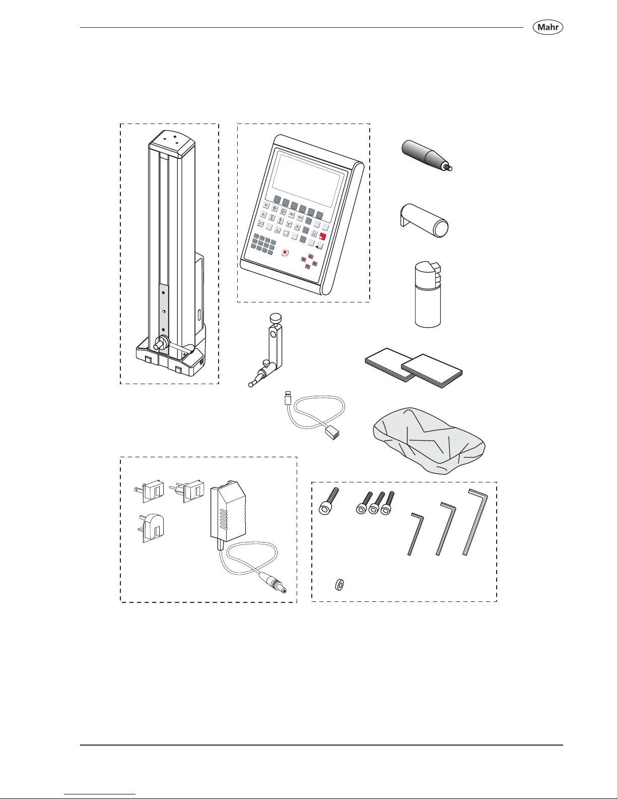
1.1 Scope of supply
C
K
M6
L
M4
3x
M
3 mmN4 mmO5 mm
G
H
2
D
M
A
X
M
IN
D
IS
P
S
T
A
T
P
R
O
G
C
O
N
F
IG
C
A
L
D
A
T
A
C
E
O
N
O
FF
1
2
3
+
4
5
6
7
8
9
0
A
B
C
D
E
F
G
H
I
J
K
L
M
N
O
P
Q
R
S
T
U
V
W
X
Y
Z
Q
u
i
c
k
0
H
e
i
g
h
t
B
I
J
F
E
D
A
P
Q
8
Mahr GmbH • Digimar 817 CLM
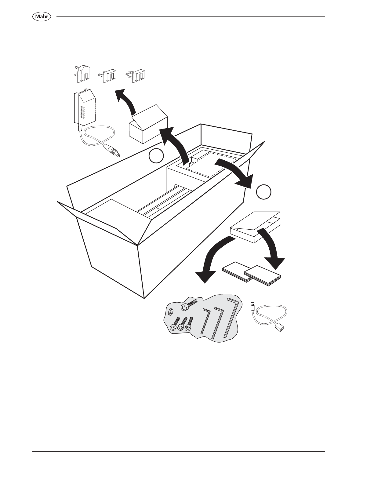
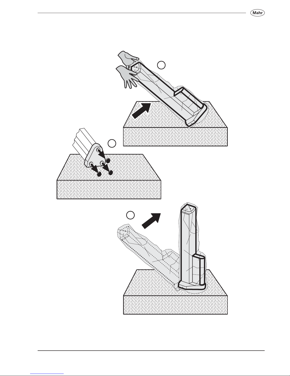
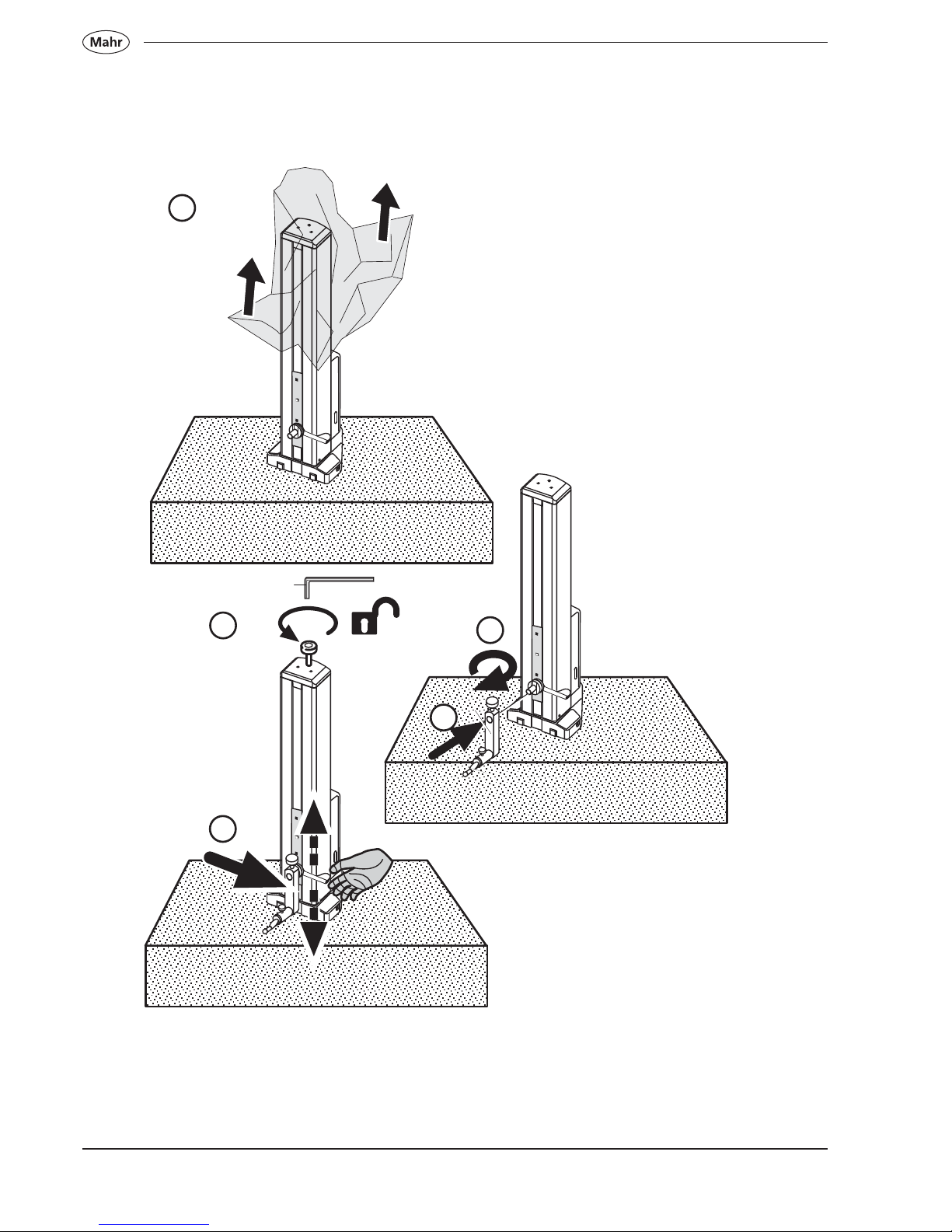
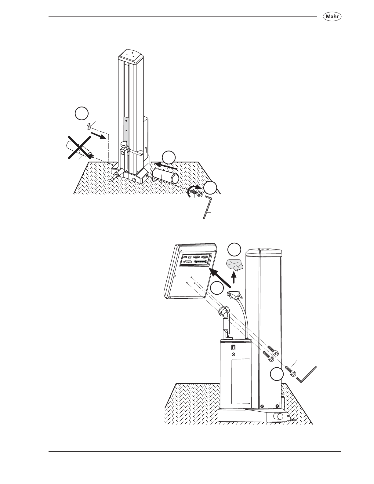
1.2 Unpacking
1
2
N
I
C
K
L
M
O
P
Q
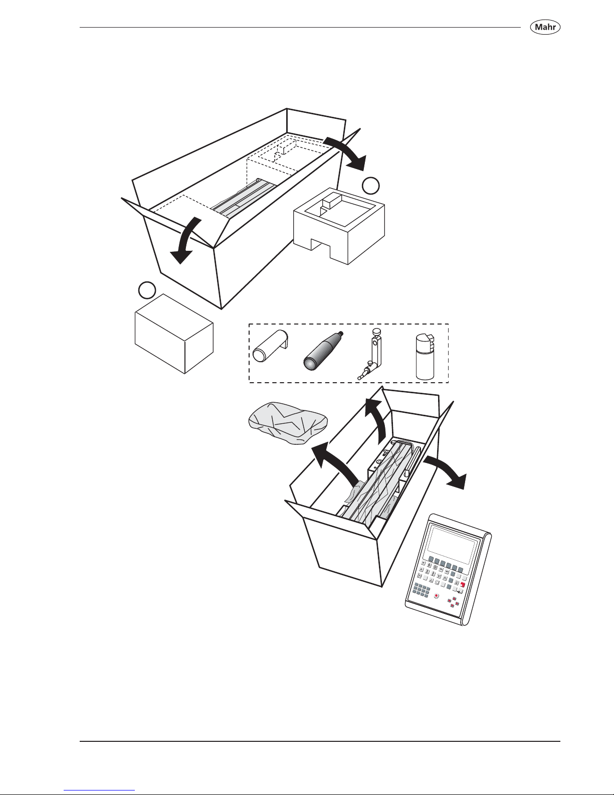
9
Mahr GmbH • Digimar 817 CLM
3
4
2D
M
AX
M
IN
DISP
ST
A
T
PROG
C
O
N
F
IG
CA
L
D
A
TA
CE
O
N
O
F
F
1
2
3
+
4
5
6
7
8
9
0
A
B
C
D
E
F
G
H
I
J
K
L
M
N
O
P
Q
R
S
T
U
V
W
X
Y
Z
Q
u
i
c
k
0
H
e
i
g
h
t
DE
F
G
H
B
J
10
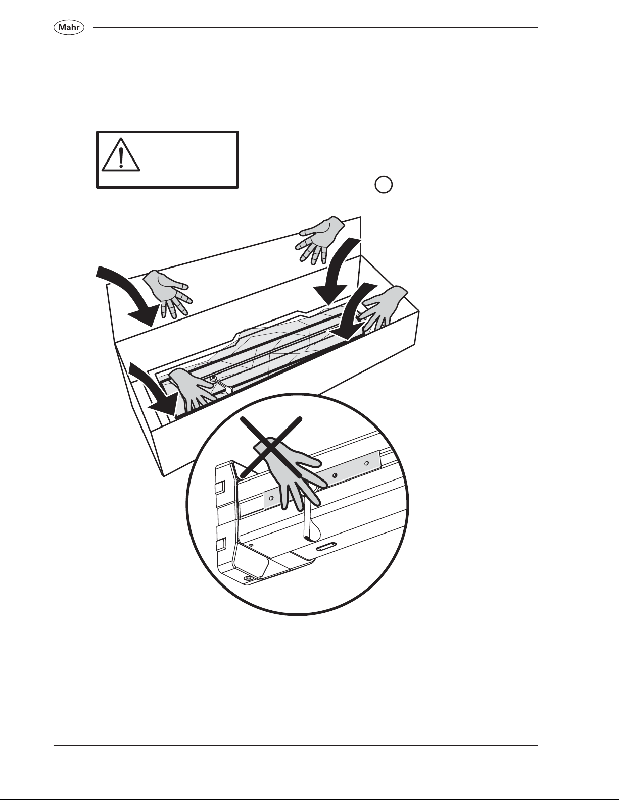
Mahr GmbH • Digimar 817 CLM
5
350 mm 25 kg
600 mm 30 kg
1000 mm 35 kg
11
Mahr GmbH • Digimar 817 CLM
6
45°
7
8
90°
12
Mahr GmbH • Digimar 817 CLM
9
11
G
H
10
12
13
M
13
Mahr GmbH • Digimar 817 CLM
B
3x L
M
19
17
18
P
D
E
K
N
14
15
16
14
Mahr GmbH • Digimar 817 CLM
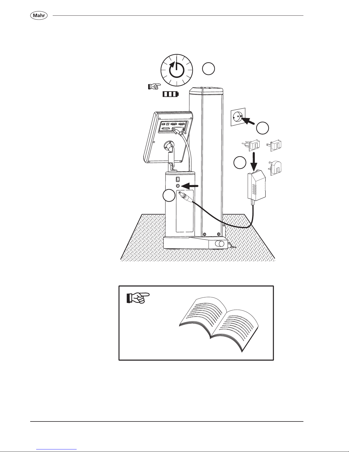
100-240 V~ / 50-60 Hz
I
~12 h
+
21
22
Euro US
UK
20
23
15
Mahr GmbH • Digimar 817 CLM
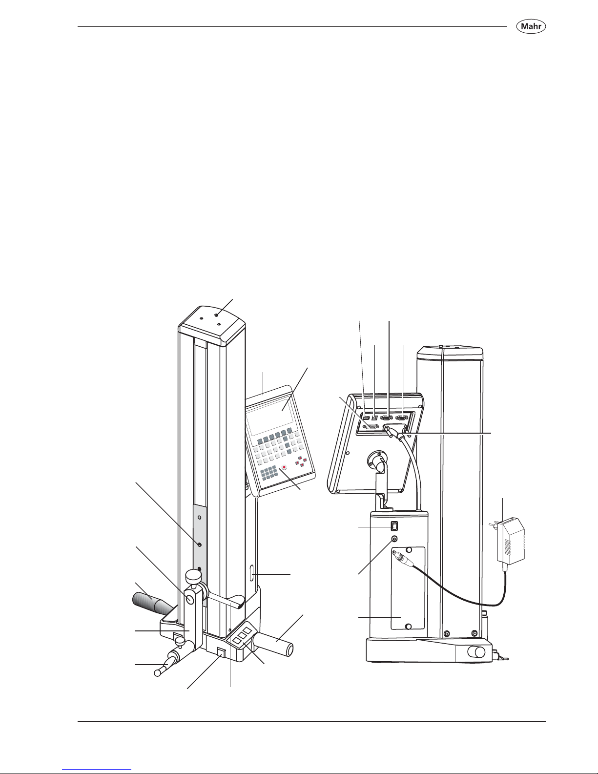
1.3 Description and explanation of the height measuring instrument
1.3.1 Height measuring instrument
1 Transport protection screw 14 Switch for activating the air bearings
2 Mount for probing element carrier 15 Socket for mains power charger
3 Probing element carrier 16 ON/OFF switch (power supply)
4 Contact point 17 Rechargeable battery compartment (accumulator)
5 Limit plate 18 Interface connection for the measuring column (HEIGHT
6 LED display GAGE)
7 Handle for manually moving the slide 19 Interface connection for digital indicators (INPUT 1)
8 Control and evaluation unit required for perpendicularity checks
9 Display 20 Interface connection for incremental probes P1514H
10 Keypad (INPUT 2) required for perpendicularity checks
11 Quick-keys 21 RS232 OUT to send individual measured values to a PC
12 Hand grip and/or a statistics printer
13 Transport handle 22 USB B port for connection to a PC
23 USB A port for connecting a for printer
24 Plug for mains power supply
1
9
10
14
12
11
7
5
3
4
2
13
6
17
15
16
18
19
21
22
23
20
24
8
16
Mahr GmbH • Digimar 817 CLM
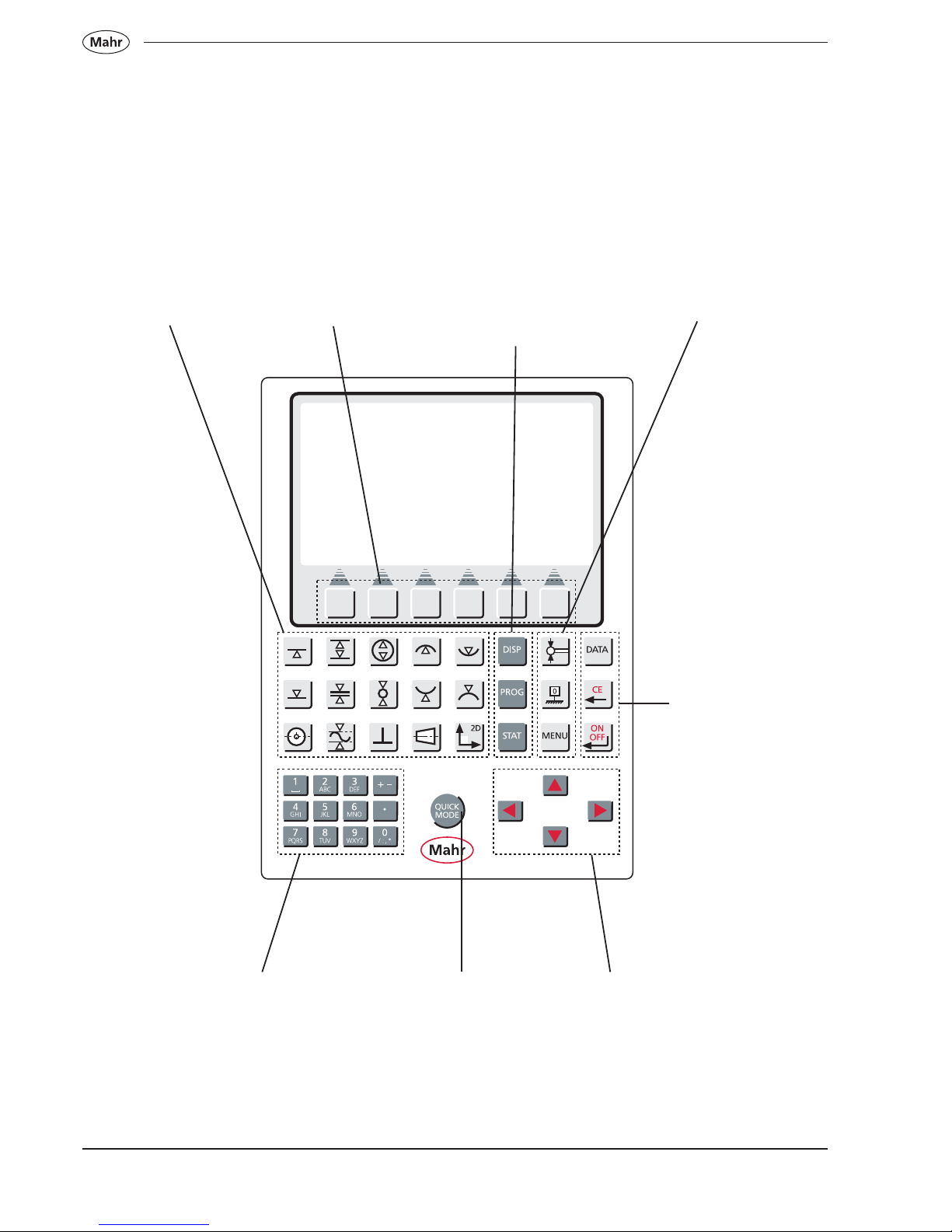
1.3.2 Keypad
Measuring function
keys
Variable
function keys
Calibration and
set up function keys
Delete and accept
function keys
Keypad
Active / deactive the
Quick Mode
Arrow keys
Evaluation function
and measuring
program keys

17
Mahr GmbH • Digimar 817 CLM
1.3.2.1 Measuring functions
– Refer to chapters 4.3 - 4.7
1.3.2.2 Evaluation functions and measuring program
Show or hide the measuring results
Measuring program functions – See chapter 7
Statistics functions – See chapter 8
Calibrate a probe – See chapter 4.1
Zero point – See chapter 4.2
Menu settings – See chapter 6
Data transmission / select data for transmission – See chapter 9.1
Delete values and return to sub menu /cancel – See chapter 5
Confirm a function – switch the Height Measuring Instrument ON / OFF
1.3.2.3 Calibration and set up functions
1.3.2.4 Delete or accept a function
18
Mahr GmbH • Digimar 817 CLM
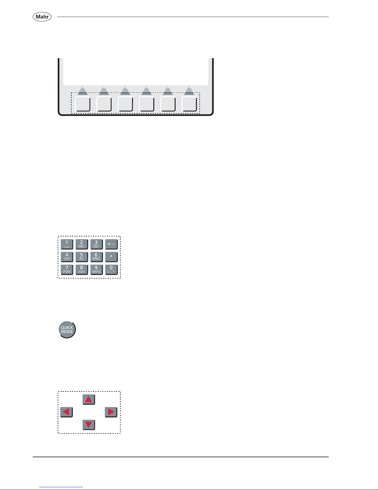
1.3.2.5 Variable function keys
Depending upon the measuring task, the bitmap symbols above the variable function keys change accordingly. By
pressing the individual key, the function will be activated or you will enter a subdirectory / lower level. The different
meanings are described in the operating instructions.
1.3.2.6 Input pad
Each key is assigned a multiple character function, by
repeatedly pressing a key the next assigned character
will appear, for example:
2 -> A -> B -> C -> 2 -> A . . .
1.3.2.7 Quick-Mode
Activate / deactivate
1.3.2.8 Arrow keys
Arrow keys left / right - Cursor jumps 5 times left / right
Arrow keys up / down - Cursor jumps once up / down
– See chapter 4.8
19
Mahr GmbH • Digimar 817 CLM
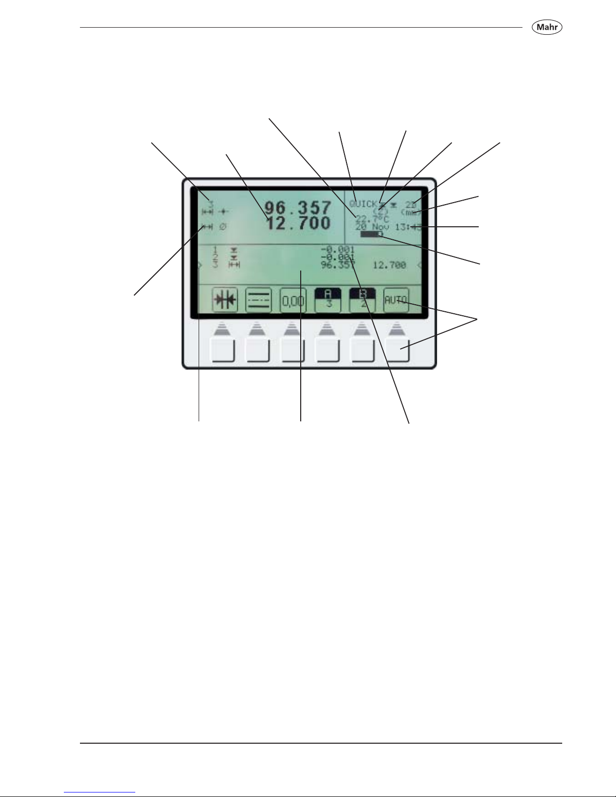
1.3.3 Display
Actual measured
value
Characteristic
number
Characteristic
symbol
Actual
character
Display field
Stored measured
values
Charging
condition of the
battery
Date and
time
Unit of
measurement
2 D Mode is
activated
Actual axis
Quick Mode
plane / bore
Quick Mode
activated/
deactivated
Temperature
Variable
function keys
20
Mahr GmbH • Digimar 817 CLM
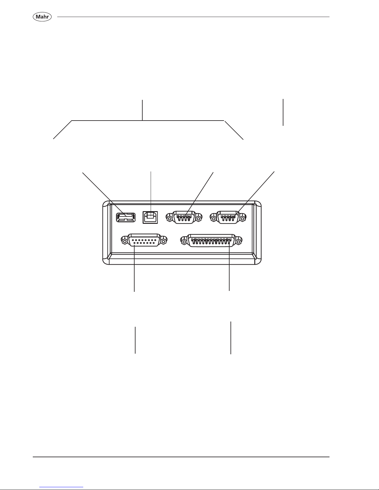
1.3.4 Interface connections
USB-Interface
Type A
Port for a USB printer
USB-Interface
Type B
PC port
RS 232
Interface
OUT
To connect either a PC
or statistics printer
RS 232
Interface
Input 1
To connect a digital
indicator (required for
perpendicularity
checks)
SUB D-Interface15-pin
To connect an
incremental probe, required
for perpendicularity checks
SUB D-Interface 25-pin
To connect to the measuring
column
See chapter 9.2 See chapter 4.4.2
See chapter
4.4.2
See chapter
1.2
21
Mahr GmbH • Digimar 817 CLM
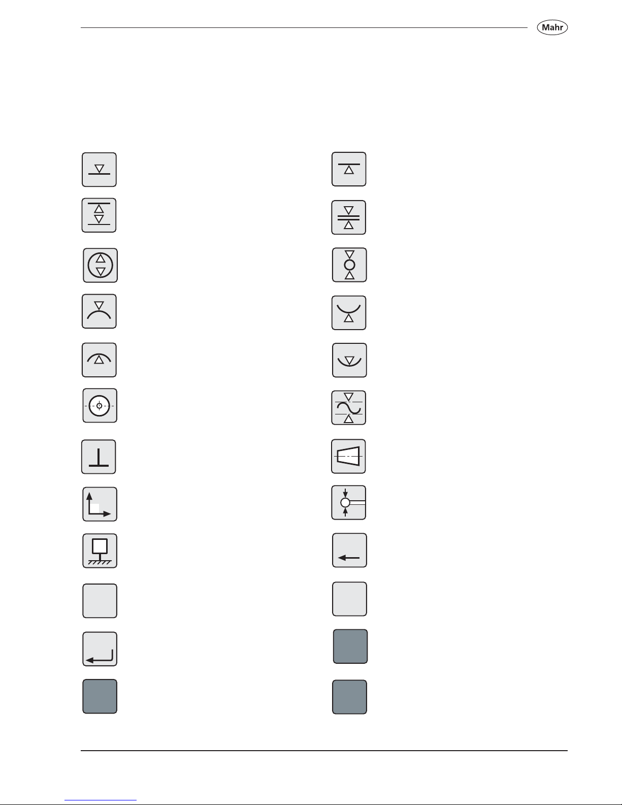
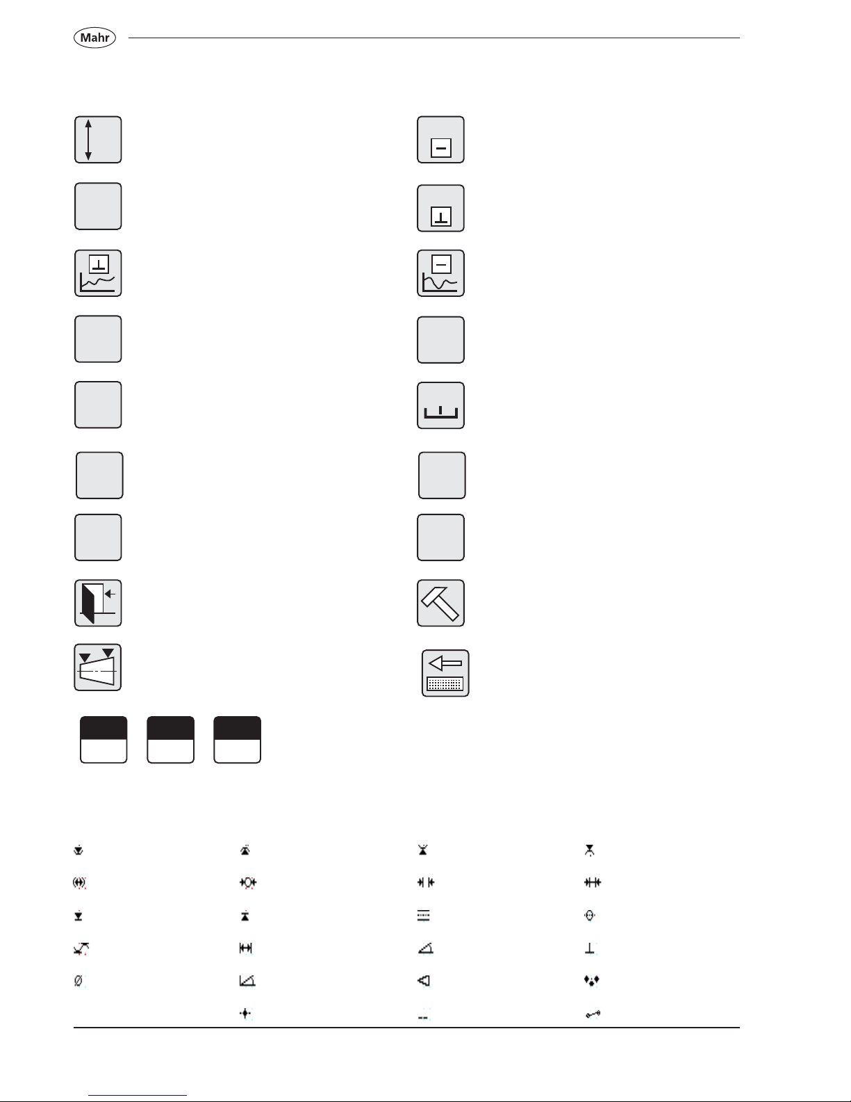
1.3.5 Description of the symbols
1.3.5.1 Keypad symbols
Contacting a plane / surface from above
Measuring a groove
Measuring a bore
Contacting a shaft from above
Contacting a bore from above
Determining the center of a bore /
displaying the position
Perpendicularity
2D-selection key
Zero point
Select data for transmission
ON / OFF / Confirm
Statistics function
2D
0
DATA
Contacting a plane / surface from below
Measuring a bar
Measuring a shaft
Contacting a shaft from below
Contacting a bore from below
Min-Max function
Measuring a taper / angle
Calibrating a probe
Delete / Return to last value
Menu settings
Measuring program functions
Display the list of measured values
ON / OFF
ON
OFF
STAT
CE
MENU
PROG
DISP
22
Mahr GmbH • Digimar 817 CLM
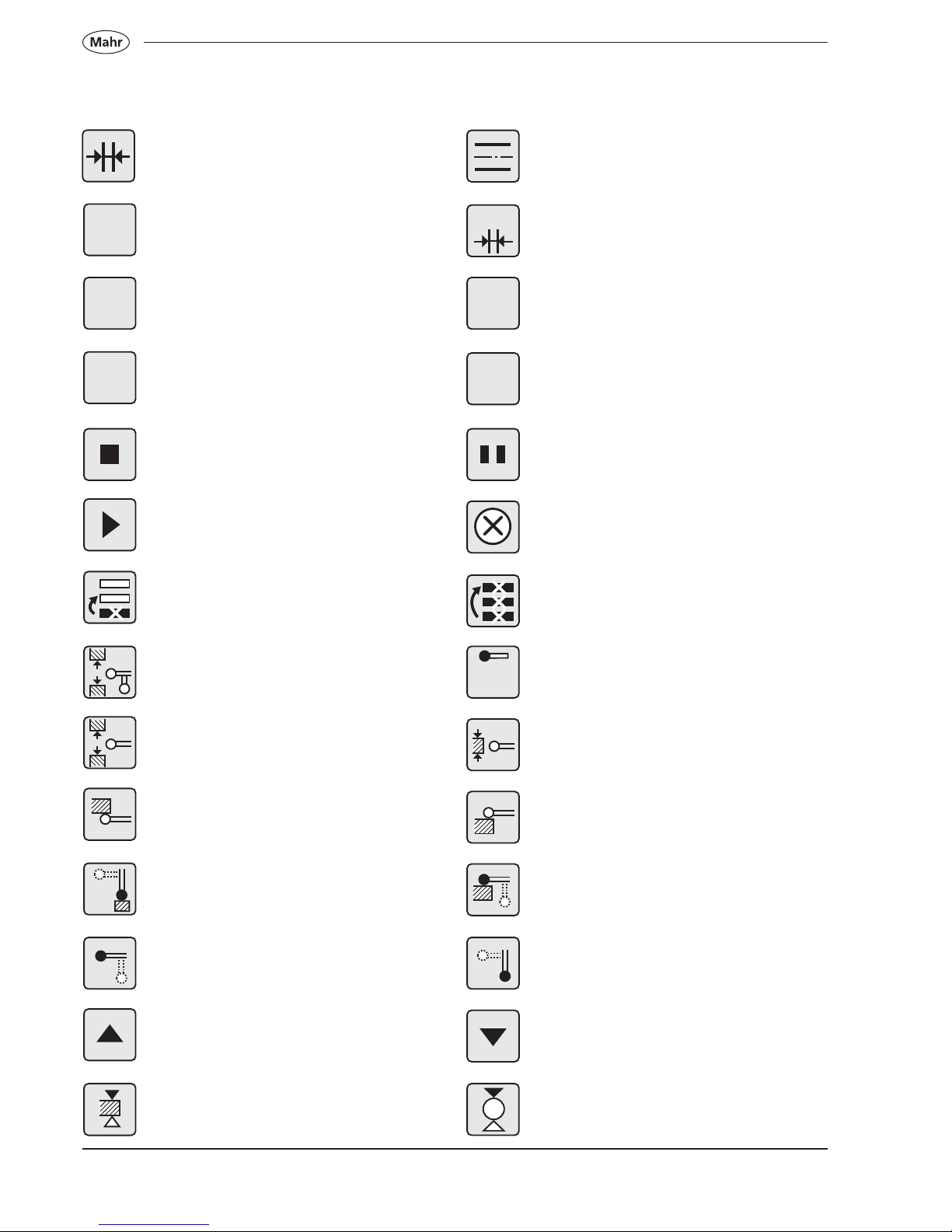
Calculate distance
Auto
Automatic zero point 01, last measured
value
Relative value
Stop / Accept
Repeat/ Continue
Delete last characteristic
Calibrate twin probe
Calibrate probe / groove
Calibrate ledge from below
Vertically contact a ledge
Select horizontal probe
Travel upwards
Contacting a bar from above
1.3.5.2 Symbols - function keys
Calculating the symmetry between
2 planes
Automatic calculation of the distance
Zero point, last measured value
Absolute value
Pause
Cancel
Delete all characteristics
Inferior calibrated value
Calibrate the probe / ledge
Calibrate ledge from above
Horizontally contact a ledge
Select vertical probe
Travel downwards
Contacting a shaft from above
AUTO
AUTO
01
REL
AUTO
0,00
ABS
?
23
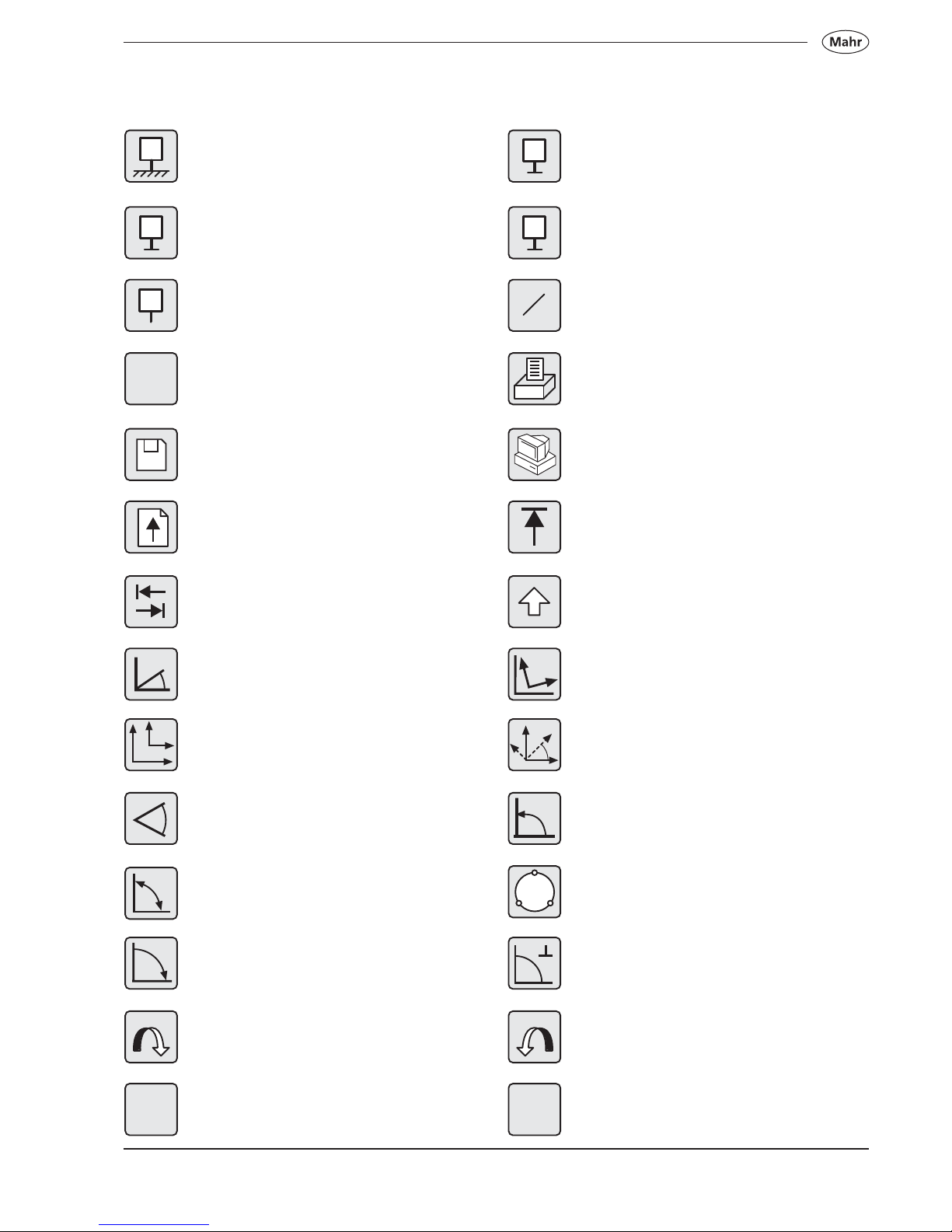
Mahr GmbH • Digimar 817 CLM
Work piece, zero point 01
Work piece, zero point 03
Change between zero points
Print
Transfer a series of measurements to a
PC
Position the cursor to the beginning
Switch between upper and lower case
Coordinate transformation
Rotate according to angle
Tilting angle α
Index circle
Determine the tilting angle with a probe
Rotate anti-clockwise
Set Z-value to zero
Set the zero point on the base plate
Work piece, zero point 02
Enter Preset
Direct / select data transmission
Store on internal memory
Paper feed
TAB-function
Determining distance and angle
between
two elements
Rotate coordinates X / Z
Determining distance and angle
between
three elements
Tilting the workpiece arithmetically
Manually enter the tilting angle
Rotate clockwise
Set X-value to zero
DATA
X
Z
z
x
0
02
PR
a
X=0
+
02
01
a
01
a
Z=0
03
a
24
Mahr GmbH • Digimar 817 CLM
Enter the traverse path
Display only the diameter
Display a perpendicularity graphic (curve)
Accept the maximum value
Display the diameter
Error character number Z
Active 2D
Quit system
Taper measurement
Characteristic
Accept straightness value
Accept perpendicularity value
Display a straightness graphic (curve)
Accept the minimum value
Bar graph
Error character number X
Deactivate 2D
Change the production data
Taper probe
1.3.5.3 Symbols - display
Bore from above Bore from below Shaft from below Shaft from above
Bore Shaft Distance, bar Distance
Contacting from above Contacting from below Symmetry Position
Min Max Distance, groove Internal angle Perpendicularity
Display diameter External angle Taper Index circle
Coordinate Straightness Distance 2D
M =
M =
M =
MIN
Z
M =
Ø
M =
MAX
Ø
?
z
?
x
2D
ON
2D
OFF
A
C
B
25
Mahr GmbH • Digimar 817 CLM
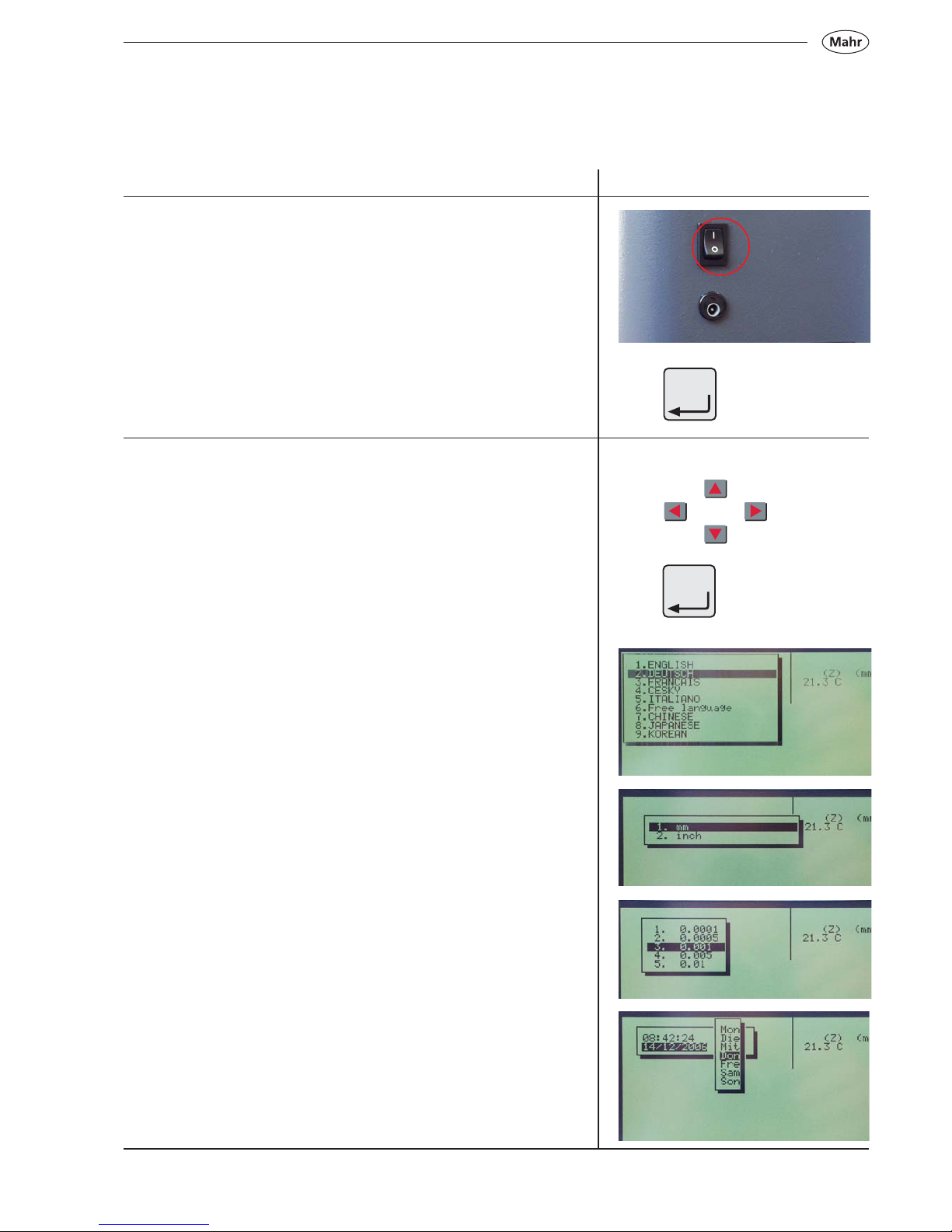
2.1 Switching ON
– Switch the mains power supply switch to ON = (1)
Press the ON/OFF key; this will start the boot up.
Note: At the first commissioning, by a RESET or when updating
the software, the following questions (the basic settings) will
appear:
2.2 Basic settings
These can be selected by using the arrow keys, confirm by pressing
the Enter key.
Enter the time and date via the keypad
Select: Language
Select: Unit of
measurement
Select: Resolution
Enter the date and time
2. Commissioning / First steps
Description / Sequence Symbols / Pictures
ON
OFF
ON
OFF
26
Mahr GmbH • Digimar 817 CLM
2.3 Setting the reference point
The measuring carriage moves automatically to the reference point
(reference point height ca. 50 mm) and sets the zero point on the base
plate.
Note: Once the zero point has been accepted, confirmation is given by
a twofold optical (LED) and acoustic signal (beep).
After the reference point has been confirmed, any zero point can be
selected.
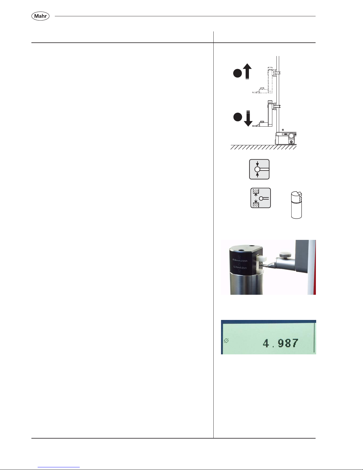
2.4 Calibrating a probe
a) Press the calibrate probe key
b) Press the function key „Calibrate in a groove“, the probe moves
automatically to the center of the groove of the setting standard.
c) Slide the setting standard, so that the probe is within the groove.
The groove will be automatically measured for a second time.
d) The determined probe constant will be displayed.
Description / Sequence Symbols / Pictures
Note:
The determined probe constant is always slightly smaller than the
actual diameter of the probe (please refer to 4.1).
a)
b)
c)
d)
2
1
27
Mahr GmbH • Digimar 817 CLM
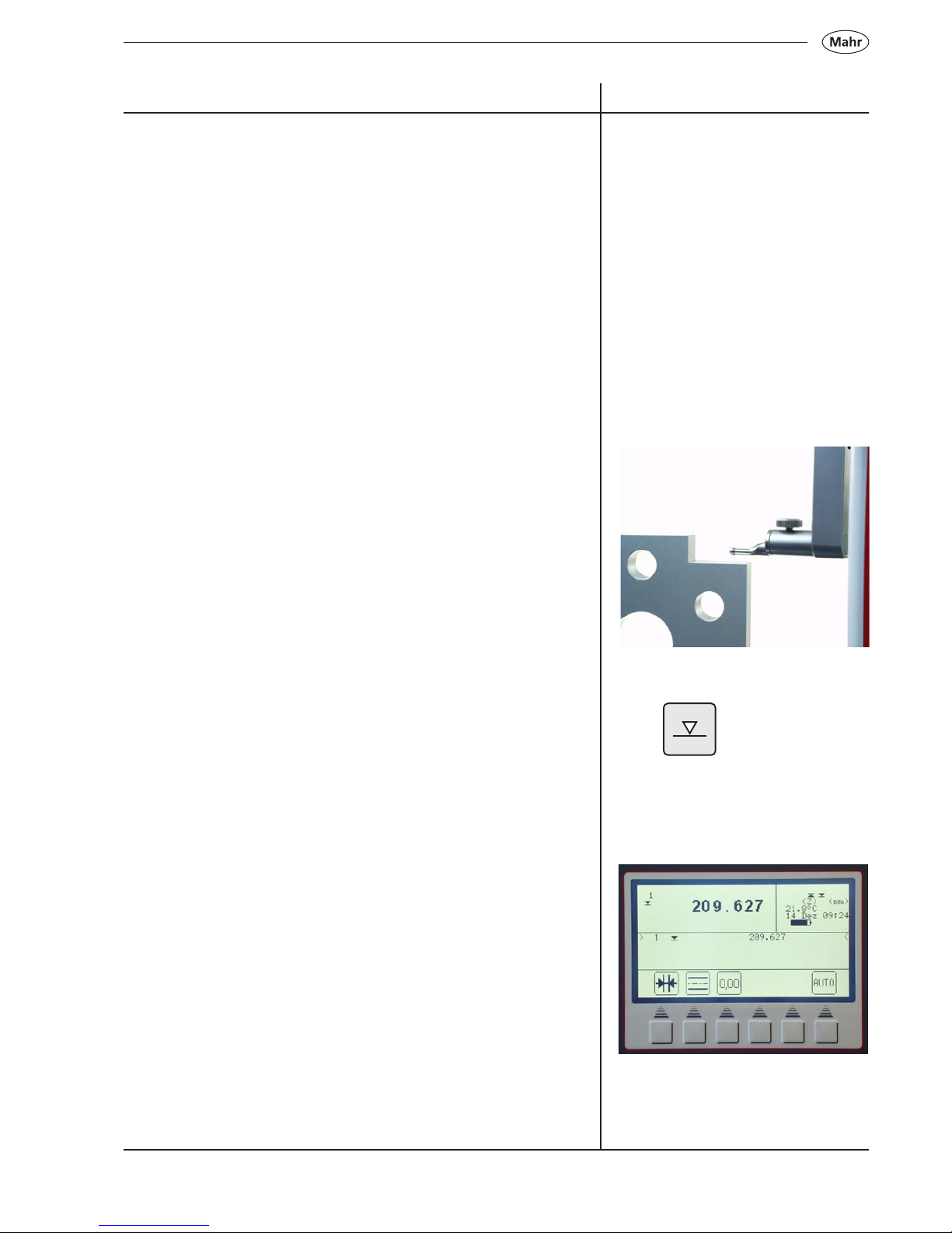
2.6 First measurement
Note:
In order to obtain highest accuracy the instrument requires at least a
warm-up period of 15 minutes.
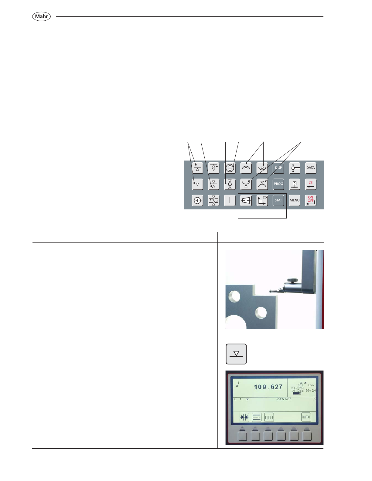
2.6.1 Contacting a plane from above
– Position the probe
– Press key to start the measuring procedure
In the upper section of the display will appear the measured value
2.5 Auto-Off function
In the basic setting mode, the background lit display switches off after
1 minute, by pressing any key the background lit display will be
reactivated.
The height measuring instrument switches off after 5 minutes.
To change this basic setting, please refer to chapter 6.10
Note: No measuring results are lost when the height measuring
instrument switches off.
Description / Sequence Symbols / Pictures
28
Mahr GmbH • Digimar 817 CLM
3.1 Start a measurement procedure with
the function keys
The function keys can be used to start different
measuring functions with one touch of a key.
The procedure is always the same:
– Position the probe either above or below the
point that is to be measured
– Press the function key to start the measuring
function
The probe automatically travels to the surface to be
measured and accepts the measured value. When
conducting dynamic measurements, where a maximum
or a minimum (bore or shaft) is to be measured either
the workpiece or the measuring instrument must then
is moved so that the measuring instrument can
determine an extreme value. When measuring with 2
contacts (e.g. a bore, groove or shaft), the first contact
must be upwards (from below).
Function keys:
1 Contacting a surface / plane from above or
below
2 Determining the center and width of a groove
3 Determining the center and width of a ledge
4 Determining the center and diameter of a bore
5 Determining the center and diameter of a shaft
6 Measuring a bore (maximum or minimum)
7 Measuring a shaft (maximum or minimum)
1 32 4 657
3 Brief guide to measurement methods
Optional
3.1.1 First measurement
3.1.2 Contacting a surface from above
– Position the probe
– Press the key to start the measuring procedure
The measured value will appear in the upper section of the display
29
Mahr GmbH • Digimar 817 CLM
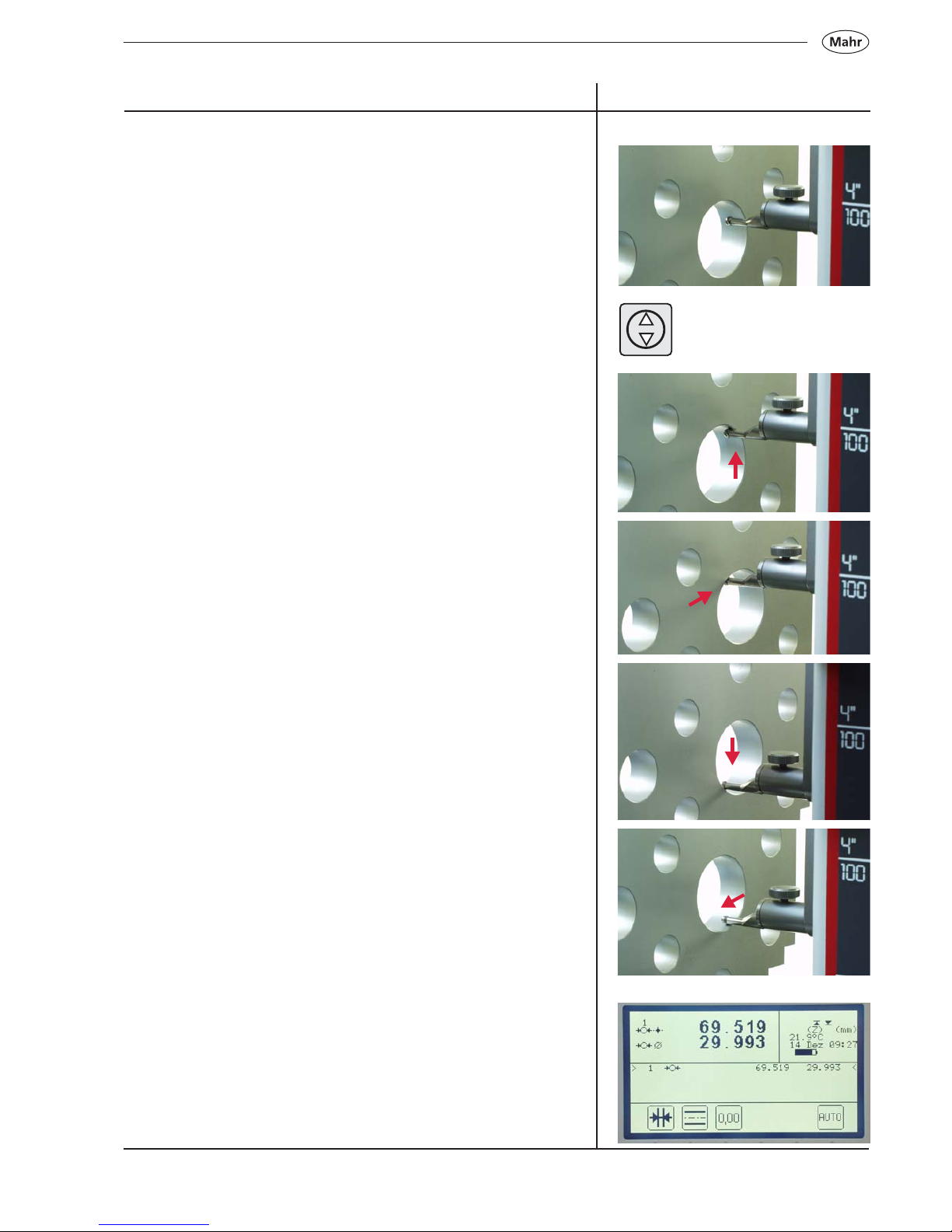
3.1.3 Measuring a bore
– Position the probe in the bore (not in the center / eccentrically)
– Press key to start the measuring procedure
– The probe will automatically travel upwards; the bore is contacted
from below
– Move the workpiece parallel to the stopping face in order to
determine the reversal point / maximum
– Acceptance of the reversal point will be confirmed by an acoustic
signal (beep)
– The probe will automatically travel downwards; the bore is
contacted from above
– Move the workpiece parallel to the stopping face in order to
determine the reversal point / maximum
– Acceptance of the reversal point will be confirmed by an acoustic
signal and the results (center and diameter) will appear in the
display
Description / Sequence Symbols / Pictures
30
Mahr GmbH • Digimar 817 CLM
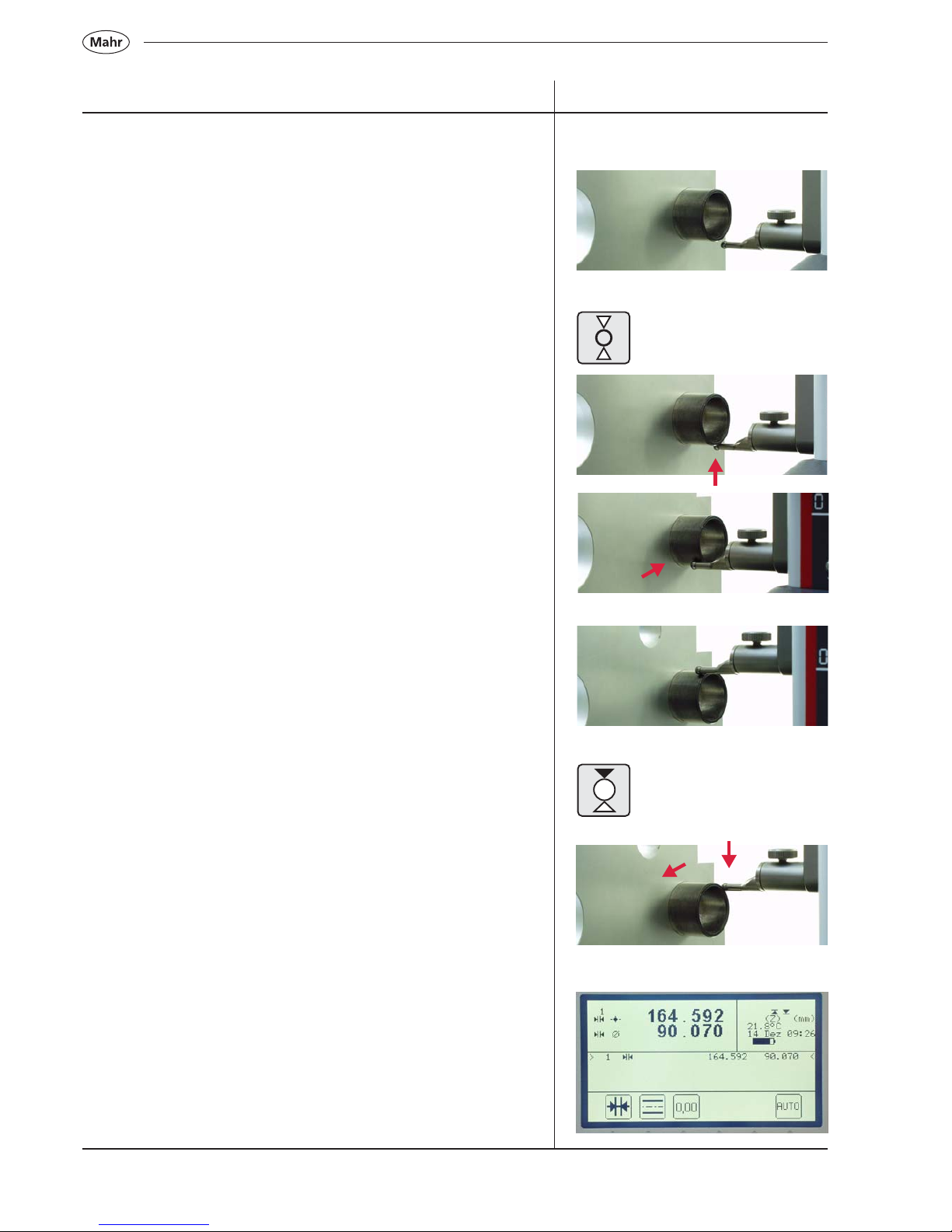
3.1.4 Measuring a shaft
– Position the probe below the shaft (eccentrically)
– Press key to start the measuring procedure
– The probe will automatically travel upwards and make contact
from below
– Move the workpiece parallel to the stopping face in order to
determine the reversal point / maximum
– Acceptance of the reversal point will be confirmed by an acoustic
signal (beep)
– Position the probe above the shaft (eccentrically).
– Press the function key „Contacting a shaft from above“
– The probe will automatically travel downwards and make contact
– Move the workpiece parallel to the stopping face in order to
determine the reversal point / maximum
– Acceptance of the reversal point will be confirmed by an acoustic
signal (beep) and the results (center and diameter) will appear in
the display.
Description / Sequence Symbols / Pictures
 Loading...