

Page 1

OPERATION
&
MAINTENANCE
MANUAL
TC670
Refrigerant Management Center
(Convertible For Use With R12 or R134a)
RTI TECHNOLOGIES, INC.
4075 East Market Street
York, PA 17402
Manual P/N 035-80342-02
Page 2

TC670
CONVERTIBLE
RECYCLING MACHINE
This Recycling Machine was
manufactured by RTI in compliance
with all applicable Underwriters
Laboratories (UL) and Society of
Automotive Engineers (SAE)
Standards and Specifications for
Refrigerant Recycling Equipment.
Your machine is initially configured
to recycle R12 or R134a.
An RTI Retrofit Kit is available for
field conversion of this machine to
recycle the alternate refrigerant for
which it is now configured. This kit
includes complete instructions, labels,
filters, hoses with service couplers, and
special tools required to make the
conversion.
Once converted by an RTI Authorized
Representative, a new Serial Label
(included in the kit) will be affixed to
the machine. This Serial Label will
certify that the machine is then in
compliance with all SAE and UL
Standards and Specifications for
Equipment to recycle the alternate
refrigerant.
Page 3

TABLE OF CONTENTS
TC670
Quick Reference Guide ........................... 1
Start-Up ....................................... 3
Safety Precautions ............................... 4
Filling the Charging Cylinder ....................... 6
Recover/Recycle................................. 8
Oil Drain & Air Purge ............................ 10
Deep Vacuum................................... 11
Hose Evacuation................................. 12
Charge/High Side................................ 13
Scheduled Maintenance & Filter Maintenance ......... 15
Problems & Solutions ............................ 16
Flow Diagram................................... Appendix
Circuit Diagram ................................. Appendix
R134a Cylinder Adapter Instructions ................. Appendix
CONGRATULATIONS: You have pur chased one of the finest Recovery, Recycling, and
Charging Machines available at any price.
Fill out and return the Warranty Card within 90 days to activate
warranty and free lifetime technical support.
Page 4

RTI Technologies, Inc.
February 5, 1996
Page 1
Page 5
RTI Technologies, Inc.
February 5, 1996
Page 2
Page 6

RTI Technologies, Inc.
START-UP INSTRUCTIONS
1) Check for any shipping damage. Place a claim with carrier if damage is discovered.
2) Complete and return the War ranty Card to activate Technical Support and Warranty Coverag e.
Warranty claims can not be honored without this warranty card on file.
BEFORE USING THE TC670
Check for any shipping damage. Place a claim with carrier if damage is discovered.
DO NOT USE A DAMAGED UNIT.
Complete and return the Warranty Card to activate technical support service and warranty coverage.
Warranty claims can not be honored without this warranty card on file.
The TC670 should not be operated or serviced by any person who has not read all the contents of
this manual. Failure to read and comply with these instructions or any one of the limitations noted
herein can result in serious injury and/or property damage.
These general instructions describe normal operation and maintenan ce situations encountered with
the TC670. The instructions should not be interpreted to anticipate every possible contingency.
It is the responsibility of the owner/user to operate the TC670 in accordance with all specificat ion s
and laws which may apply.
The following pages contain rules for safe operation of the TC670. Taking precedence over any
specified rule listed herein, however, is the most important rule of all:
"USE COMMON SENSE"
A few minutes spent reading these instructions can make an operator aware of dangerous practices
to avoid and precautions to take for his own safety and the safety of others.
A regular schedule of inspection of the TC670 should be established and records maintained with
special attention given to Hoses, Compressor Oil Level, Moisture Indicator, and Filters.
February 5, 1996
Page 3
Page 7
RTI Technologies, Inc.
SAFETY PRECAUTIONS
! Recover, Recycle, and Charge only the refrigerant for which the machine is configured.
! Wear safety glasses and protective gloves. Refrigerant has a very low boiling point and can
cause frostbite.
! Follow the TC670 operati ng procedures sequentially to avoid prematurely disconnecting hoses
or opening valves which may release refrigerant to the atmosphere.
! Do not expose the TC670 to moisture or operate in wet areas.
! Use the TC670 in locations with mechanical ventilation that provides at least four air changes
per hour.
! Hoses used with the TC670 must have shutoff devices within 12 inches of the connection point
to the system being serviced to minimize the introduction of Non-condensable Gas (Air) into
the TC670 and the release of refrigerant when being disconnected.
! Disconnect power before performing any maintenance or service on the TC670.
! Avoid using an extension cord with the TC670. If ne cessary, use a good condition, UL listed,
3-wire grounded, #14 AWG extension cord of the shortest possible length.
! Connect the TC670 to a properly protected, grounded receptacle. Do not over load the cir cuit.
! Do not allow the TC670 to remain unattended in the Charge Mode with power On. Th e Charg e
Cylinder Heater will be energized creating a high pressure condition.
NEVER TURN THE CYLINDER UP-SIDE-DOWN.
DO NOT CONNECT THE TC670 TO THE LIQUID SIDE OF ANY
A/C SYSTEM WITH A CAPACITY GREATER THAN 4 LBS.
REFRIGERANT IN A/C SYSTEMS HAVING LARGER CAPACITIES
MUST BE RECOVERED FROM THE VAPOR SIDE ONLY.
NEVER CONNECT THE TC670 TO THE LIQUID PORT OF A
CYLINDER OF REFRIGERANT TO FILL THE TC670 CHARGE CYLINDER.
FAILURE TO FOLLOW THE ABOVE MAY CAUSE THE TC670 COMPRESSOR TO
FAIL AND VOID THE WARRANTY.
February 5, 1996
Page 4
Page 8

RTI Technologies, Inc.
i
i CAUTION T
ii
Avoid breathing refrigerant or lubricant vapor or mist.
Exposure may irritate eyes, nose and throat.
If accidental system discharge occurs, ventilate work area before resuming
service.
Additional health and safety information may be obtained from refrigerant and
lubricant manufacturers.
Special Considerations with R134a
R134a has been shown to be nonflammable at ambient temperature and
atmospheric pressure. Howev er, tests under controlled conditions have indicated
that, at pressures above atmospheric and with air concentrations greater than 60%
by volume, R134a can form combustible m ixtures.
While it is recognized that an ignition source is also required for combustion to
occur, the presence of combustible mixtures is a potentially dangerous situation
and should be avoided.
Under n o c ircumstances s hould a ny e quipment b e p ressure t ested o r l eak
tested w ith A ir/R134a m ixtures. D o n ot u se c ompressed a ir ( shop a ir) f or l eak
detection in R134a systems.
February 5, 1996
Page 5
Page 9

RTI Technologies, Inc.
FILLING THE CHARGING CYLINDER
A/C Systems requiring service often do not ha ve a fu ll charge of refrig erant. To avoid unnecessary
repositioning of hoses it is recom men ded that the TC670 be filled until about 3 pounds of liquid
refrigerant can be seen in the Charging Cylinder Sight Glass. The Sight Glass is visible through a
slotted opening on the front of the TC670.
Figure 1 Filling the Cylinder
To fill the TC670 Charge Cylinder, refer to Figure 1 and follow these steps:
1. Connect the Low Side Blue Hose to the VAPOR port of a cylinder of new or recycled
refrigerant. An adapter is provided with the TC670 (R134a) which permits the Field Service
Coupler to be attached to the .500 ACME fitting on the cylinder of refriger an t (See instruction
sheet in Appendix).
If the cylinder has two ports, observe that the embossed marking on the cylinder knob says
VAPOR or GAS. Do not rely on color coding of the knobs on the valves.
DO NOT CONNECT TO THE LIQUID VALVE.
DO NOT TURN THE CYLINDER UP-SIDE-DOWN.
INTRODUCTION OF LIQUID INTO THE TC670 MAY DAMAGE THE
COMPRESSOR AND VOID THE WARRANTY.
February 5, 1996
Page 6
Page 10

RTI Technologies, Inc.
2. Press top (ON) of rocker switch marked RECOVER/RECYCLE.
The TC670 will recover and recy cle refrigera nt into the Charging Cy linder. Observe the liquid
refrigerant level rise in the Charging Cylinder Sight Glass and when at approximately 3 lbs.
close the valve on the refrigerant cylinder.
HINT: Heating of the cylinder of refrigerant with an RTI Heat Belt (P/N 026-80092-00)
will speed the recovery process.
Allow the TC670 to continue running until the Low Side Gauge shows a vacuum. This will
evacuate the Blue Hose.
3. Press bottom (OFF) of rocker switch marked RECOVER/RECYCLE.
... NOTE ...
As ref rigerant is processed by the TC670, temperature variations can cause
vapor to change to liquid which may temporarily settle in various internal
components.
If a known amount of refriger ant has b een introduced into the TC670 it may
not all be seen in the Charging Cylinder Sight Glass.
This is normal and nothing to be concerned about. Refrigerant has no t been
lost.
The sight glass does not indicate the am ount of refrigerant recovered.
It is only accurate for determining the amount of refrigerant charg ed out to
the vehicle A/C System while in the Charge Mode of operation.
February 5, 1996
Page 7
Page 11

RECOVER/RECYCLE
RTI Technologies, Inc.
Figure 2 Recover/Recycle
To Recover/Recycle, refer to Figure 2 and follow these steps:
1. Attach Red and Blue Hoses to the A/C system per the vehicle manufacturer's instructions.
Note For R134a Machines
Field Service Couplings on the ends of Service Hoses are of a special design.
The valves have LEFT HAND threads which makes operation opposite to that of others.
To Close... Turn Counter-clockwise
To Open... Turn Clockwise
The valves MUST BE CLOSED before connecting or disconnecting Field Service Couplings.
2. Open High and Low Gauge Valves.
3. Open Red and Blue Hose Valves.
4. Press top (ON) of rocker switch marked RECOVER/RECYCLE.
February 5, 1996
Page 8
Page 12

RTI Technologies, Inc.
The TC670 will automatically recover and recycle refrigerant from the A/C System until a
vacuum is sensed. This vacuum level can be seen on the Low Side Gauge.
!!!! DO NOT TURN THE TC670 OFF OR DISCONNECT HOSES !!!!
A small quantity of Liquid refrigerant will probably still remain in the A/C System. This can
be detected by observing an increasing pressure reading on the Low Side Gauge.
As pressure increases to a preset level, the TC670 will automatically cycle on and off to
continue recovering refrigerant.
Allow this automatic sequence to repeat until the va cuum le v e l re mains c onstant fo r at le ast 2
minutes.
... NOTE ...
Several audible changes may be heard during the recovery and recycling
process.
Refrigerant flow through check valves causes a "sizzle-type" sound.
These changing "noises" are normal and nothing to be concerned about.
5. Close Red and Blue Hose Valves.
6. Close High and Low Gauge Valves.
7. Press bottom (OFF) of rocker switch marked RECOVER/RECYCLE.
PURGE REQUIRED OR CYLINDER FULL LIGHT:
This Light will illuminate if either...
1) The Charging Cylinder has filled to capacity: Go to Page 13
2) Pressure on the Purge Gauge approaches 250 psig: Go to Page 10
February 5, 1996
OR
Page 9
Page 13

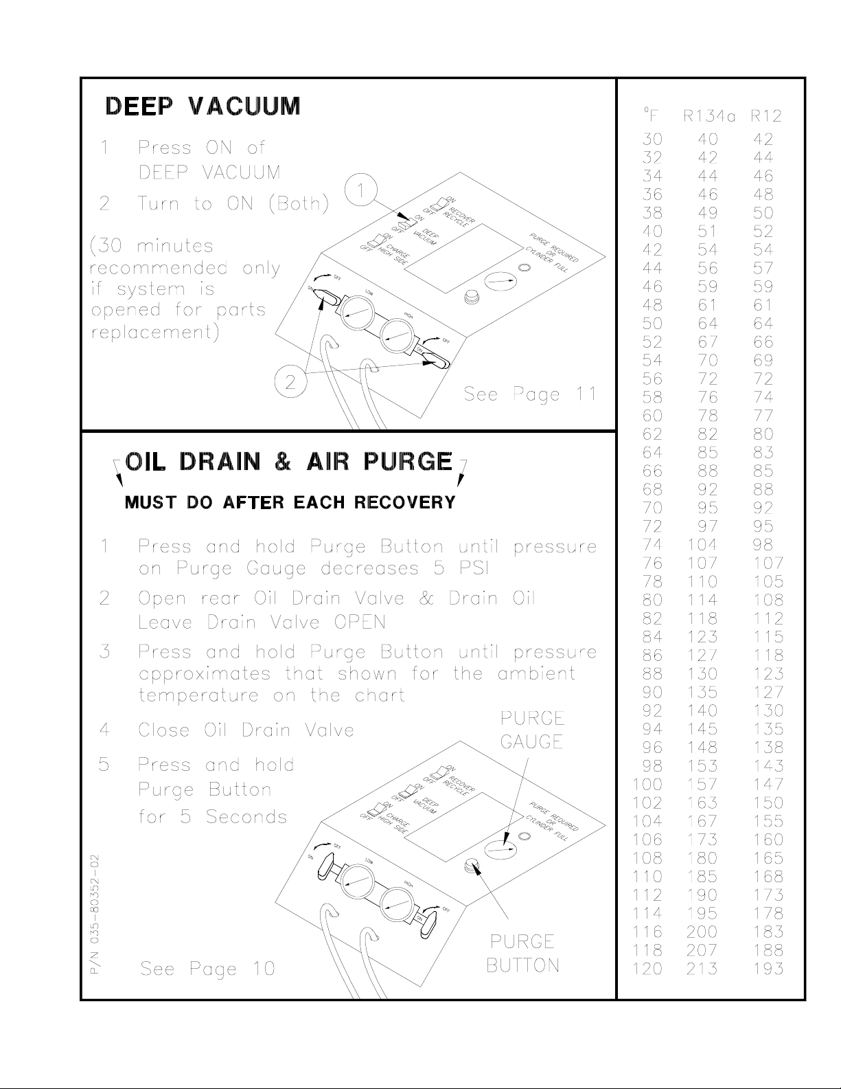
OIL DRAIN & AIR PURGE
Oil and Non-condensable Gas (Air) are separated from
the recovered refrigerant and MUST be removed
following EACH recycling procedure as follows:
1. MOMENTARILY turn the Purge Valv e (To the
right of the Purge Chart) clockwise and hold until
the pressure reading on the Pressure Gauge above
this valve drops one small graduation mark
(approximately 10 PSIG).
2. SLOWLY open the Oil Drain Valve (Lower left
side on back of TC670) to vent Non-condensable
Gas and drain any oil which may have been
removed from the A/C System. A plastic cup is
provided to collect the oil.
Unless the A/C System had previously been
overfilled, the TC670 will typically not remove
more than a tablespoon of oil, making replenishment
unnecessary.
Leave the Oil Drain Valve open.
3. Determine the room temperature.
4. Locate the pressure (PSIG) corresponding to this
room temperature ( 0 F) in the chart on the top of th e
TC670. This chart is reproduced at the right.
If the pressure indicated on the gauge is greater than
that determined from the chart...
SLOWLY turn clockwise and hold open the
Purge Valve until the gaug e pressure equals that
shown in the chart. Any Non-condensable Gas
will be vented through the Oil Drain Valve.
5. Close the Oil Drain Valve.
6. Turn the N/C Vent Valve clockwise and hold for
approximately 5 seconds. This permits any residual
Non-condensable Gas to be recirculated for
reprocessing during the next recycle procedure.
RTI Technologies, Inc.
0F R12 R134a
30 42 40
32 44 42
34 46 44
36 48 46
38 50 49
40 52 51
42 54 54
44 57 56
46 59 59
48 61 61
50 64 64
52 66 67
54 69 70
56 72 72
58 74 76
60 77 78
62 80 82
64 83 85
66 85 88
68 88 92
70 92 95
72 95 97
74 98 104
76 102 107
78 105 110
80 108 114
82 112 118
84 115 123
86 118 127
88 123 130
90 127 135
92 130 140
94 135 145
96 138 148
98 143 153
100 147 157
102 150 163
104 155 167
106 160 173
108 165 180
110 168 185
112 173 190
114 178 195
116 183 200
118 188 207
February 5, 1996
Purge Chart
Page 10
Page 14

RTI Technologies, Inc.
DEEP VACUUM
If the A/C System is " opened" for replacing components, it is important to draw a deep v acuum on
the system before recharging with refrigerant. This vacuuming process not only removes air from
the system, but just as importantly, will remove any moisture in the system.
A Vacuum Pump in the TC670 provides the capability of performing this "Deep Vacuum and
Dehydration". The following steps should be followed:
Figure 3 Deep Vacuum
To Deep Vacuum the A/C System, refer to Figure 3 and follow these steps:
1. Connect Red and Blue Hoses to the high and low sides of the A/C System.
2. Open Low and High Gauge Valves.
3. Open Red and Blue Hose Valves.
4. Press top (ON) of rocker switch marked DEEP VACUUM.
5. The Vacuum Pump will start and the TC670 will start drawing a vacuum which will be
indicated by a dropping pressure on the Low Gauge.
NOTE... If pressure is sensed at the Red and Blue Hoses on the TC670, the Vacuum Pump will
not start, as this would result in venting of refrigerant.
If this occurs, perform the recover/recycle operation described earlier.
ALSO... It may be necessary to momenta rily loosen the Blue Hose to break the vacuum a nd allow
the pump to start if its operation has been interrupted.
February 5, 1996
Page 11
Page 15

RTI Technologies, Inc.
HOSE EVACUATION
It's important that Air not be introduced into the A/C System during a Charging procedure. If a Deep
Vacuum procedure was performed previously, the following Hose Evacuation Procedure is not
required. If the service valves on the hoses have been open, the following procedure must be
performed:
Figure 4 Hose Evacuation
To Evacuate Hoses, refer to Figure 4 and follow these steps:
1. Close Red and Blue Hose Valves.
2. Open High and Low Gauge Valves.
3. Press top (ON) of rocker switch marked RECOVER/RECYCLE.
4. Let the TC670 run until a vacuum is seen on the Low Side Gauge.
5. Turn High and Low Gauge Valves to OFF.
6. Press bottom (OFF) of rocker switch marked REC OVER/RECYCLE. All Air has now been
removed from the Hoses.
7. Vent any Non-condensable Gas as described in the previous section.
February 5, 1996
Page 12
Page 16

CHARGE - HIGH SIDE
RTI Technologies, Inc.
Figure 5 Charge - High Side
To Charge Refrigerant, refer to Figure 5 and follow these steps:
1. Perform Hose Evacuation described previously.
2. Connect Red Hose to the A/C Syst em high side per the vehicle manufacturer's instructions. Do
not open the hose valve.
3. Press top (ON) of rocker switch marked CHARGE/HIGH SI DE. The Charge Cylinder will now
be heating to develop pressure for charging.
4. Open High Gauge Valve. The Low Gauge Valve and both Hose Valves should be closed.
5. Determine the refriger ant capacity of the A/C syste m to be charged. This data is usually printed
on a tag located on the accumulator or under the hood of t h e vehicle. Convert this quantity to
tenths of a pound for setting the TC670 charge indicator.
The following will determine where to set the indicator prior to starting the charge mode:
(TC670 Liquid Level) - (A/C System Capacity) = Indicator Setting
February 5, 1996
Page 13
Page 17

RTI Technologies, Inc.
EXAMPLE: The level of liquid visible in the TC670 Charging Cylinder Sight Glass is 7.4 lbs.
and the A/C system capacity is 3.2 lbs. The following calculation results...
(7.4) - (3.2) = 4.2
Therefore, the sliding indicator should be set at 4.2 lbs. in this example. When the
liquid level lowers to the 4.2 lb. mark, a charge of 3.2 lbs. will have been de livered
NOTE... The Sight Glass on the Char ging Cylinder has markings for both R12 and
R134a. Always use the correct scale for accurate charging.
6. Open Red Hose Valve. Do not start the Vehicle's Engine. Refrig erant will flow into the high
side of the A/C System. Closely monitor the liquid le vel as it lower s in the Charging Cy linder
Sight Glass.
7. Close High Gauge Valve as soon as the refrigerant level drops to the sliding indicator.
9. Press bottom (OFF) of rocker switch marked CHARGE/HIGH SIDE.
The vehicle can now be started and the A/C system checked by monitoring Gauge pressures.
Evacuate the hoses per the preceding section "Hose Evacuation"
Always close all valves before disconnecting hoses.
NOTE: The preceding is the recommended method of charging with the TC670.
Some vehicle manufacturers may specify connecting only to the Low Side of the
A/C System. Always follow the manufacturer ’s recommended procedures. The
above instructions would have to be modified accordingly.
February 5, 1996
Page 14
Page 18

RTI Technologies, Inc.
SCHEDULED MAINTENANCE
BEFORE EACH USE...
Check the oil level in the Compressor DAILY before using.
The Oil Level Sight Tube is vi sible throug h a cut-out in the left side of the black Compressor Cover
at the bottom of the TC670.
The oil level should be visible in the small nylon tube.
If oil is not visible or is above the middle of the cut-out call Technical Support at 800-468-2321.
MONTHLY...
Clean the Condenser to maintain high efficiency performance of the TC670. Disconnect power and
remove the Compressor Compartment Cover and blow compressed air through the cooling fins of
the Condenser to remove any debris.
Do not bend the fins on the Condenser coil. Air flow will be restricted and cause damage to the
TC670. Replace the Compressor Compartment Cover before applying power to the TC670.
FILTER MAINTENANCE
Monitor the Moisture Indicator for a color change from BLUE to PINK. When the TC670 is new
and immediate ly a fter c hanging Combo Filter s, the Moisture Indicator may show PINK. This is due
to the exposure to air and does not indicate inadequate filter performance.
Two Combo Filters are installed on the rear of the TC670.
Both Filters must be changed every year OR when the Moisture Indicator shows "Wet".
February 5, 1996
Page 15
Page 19

RTI Technologies, Inc.
PROBLEMS & SOLUTIONS
On rare occasion t he TC670 may seem to be performing differently or not at all. Experience has
shown that varying operating conditions can affect the performance characteristics of the TC670.
The temperature of the vehicle A/C System will affect how the TC670 performs.
Following are typical problems with explanations of the possible cause and solution.
PROBLEM: My TC670 worked fine all las t Summer. I got it out today for the first service job
this Spring and it is very slow in evacuating the system.
SOLUTION: Today's Spring temperature may be much lower than the average temperatures
during the summer months. Maybe the vehic le w as br ought in from outside where
the temperature is very low.
The refrigerant in the vehicle will not be under as high a pressure at lower
temperatures and the TC670 will take longer to dra w a va c uum. More cy cles may
be required to completely recover the refrigerant.
PROBLEM: I put 5 lbs. of refrigerant into the TC670 using the Recycle Mode. When I checked
the sight glass on the Charging Cylinder, there was less than 5 lbs. I lost
Refrigerant. The unit must leak.
SOLUTION: Due to temperature changes, some refrigerant may condense into liquid form and
stay in tubes and other components in the circuit preceding the Charging Cy linder.
This is normal and will explain wh y all refriger ant is not visible in the sight glass.
PROBLEM: I can not get the TC670 to draw a vacuum as indicated on the Low Side Gauge.
SOLUTION: Check Hoses for restrictions.
PROBLEM: When I try to fill the Charging Cylinder from an auxiliary cylinder of clean
refrigerant, the TC670 is really slow or shuts down.
SOLUTION: The auxiliary cy linde r will cool due to the vaporiz at ion of r efrig erant. This ca uses
the pressure to decrease.
Use a heat belt to increase the speed of recycling by the TC670.
February 5, 1996
Page 16
Page 20

RTI Technologies, Inc.
PROBLEM: I turned a 30 lb. cylinder of new refrigerant up-side-down to pre-charge the
Charging Cylinder with liquid. The Charging Cylinder didn't fill and now the
TC670 won't recover from an A/C system.
SOLUTION: The TC670 has been overloaded with liquid refrigerant (See Safety Precaution
Section at the beginning of this manual).
... WARNING ...
IF A CYLINDER IS TURNED UP-SIDE-DOWN, THE
TC670 WILL OVERFILL WITH LIQUID
REFRIGERANT. THIS OVER FILLS THE SUCTION
ACCUMULATOR WITH LIQUID.
FROST ON THE OIL DRAIN ON THE REAR OF THE
TC670 IS A GOOD INDICATION OF THIS
OCCURRENCE.
THIS SYMPTOM IS CAUSE FOR CONCERN AS LIQUID
REFRIGERANT WILL BE FORCED INTO THE
COMPRESSOR.
THIS CAN DESTROY THE COMPRESSO R AND WILL
VOID THE WARRANTY.
The safest method to remove the excess liquid which has collected in the Suction
Accumulator is to drain it from the Oil Drain on the ba ck of t he T C670 as follows:
Draw a deep vacuum (25 to 29 In. Hg.) on an empty cylinder and connect it to the
Oil Drain Valve. Open the cylinder valve and the Oil Drain valve.
Close the valves and disconnect the cylin der after the liquid has been drawn into the
cylinder. This refrigerant can now be recycled by the TC670 following normal
recycling procedures.
If the above suggested solutions do not solve the problem, call the phone number shown on the
Serial Label on the rear of the machine and one of our technicians will help diagnose the cause.
Please have the Serial Number available for reference.
February 5, 1996
Page 17
Page 21

Page 18
Page 22

Page 19
Page 23

Page 20
 Loading...