

Page 1
OPERATION
&
MAINTENANCE
MANUAL
TC670RR
Refrigerant Recycling Center
RTI Technologies, Inc.
10 Innovation Drive
P.O. Box 3099
York, PA 17402 USA
717-840-0678 ext. 259
tech@rtitech.com
035-81079-00
Page 2

TABLE OF CONTENTS
TC670RR
Start Up & Safety Operation .................2
Recover - Recycle ........................3
Oil Drain & Air Purge ......................4
Vacuum ................................5
Self Evacuation...........................6
Scheduled Maintenance & Filter Maintenance . . . 7
Component Setup .........................8
Parts Identification ........................9
Flow Diagram ............................10
Schematic Diagram .......................11
EC Declaration of Conformity for Machinery.....12
Page 3

STARTUP & SAFE OPERATION
9 Do not use a damaged unit. Check for shipping damage and place a claim with carrier if
damage is discovered.
9 The TC670RR should not be operated or serviced by any person who has not read all the
contents of this manual.
9 This manual describes normal operation and maintenance for the TC670RR. Failure to
read and comply with these instructions or any one of the limitations noted herein can
result in serious injury and/or property damage. The instructions should not be interpreted
to anticipate every possible contingency.
9 It is the responsibility of the owner/user to operate the TC670RRin accordance with all
laws and specifications which may apply.
9 Avoid breathing refrigerant or lubricant vapor. Exposure may irritate eyes, nose and
throat. Ventilate work area if accidental system discharge occurs.
9 Wear safety glasses and protective gloves. Refrigerant has a very low boiling point and
can cause frostbite.
9 Follow the TC670RR operating procedures sequentially to avoid prematurely
disconnecting hoses or opening valves which may release refrigerant to the atmosphere.
9 Do not expose the TC670RR to moisture or operate in wet areas.
9 Use the TC670RR in locations with ventilation that provides at least four air changes per
hour.
9 Hoses must have shutoff devices within 12 inches of the connection point to the A/C to
minimize the introduction of air into the TC670RR and the release of refrigerant when
being disconnected.
9 Disconnect power before performing any maintenance or service on the TC670RR.
Special Considerations with R134a
R134a has been shown to be nonflammable at ambient temperature and atmospheric
pressure. However, tests under controlled conditions have indicated that at pressures above
atmospheric and with air concentrations greater than 60 percent by volume, R134a can form
combustible mixtures.
While it is recognized that an ignition source is also required for combustion to occur, the
presence of combustible mixtures is a potentially dangerous situation and should be avoided.
Under no circumstances should any equipment be pressure tested or leak tested with air and
R134a mixtures. Do not use compressed air for leak detection in R134a systems.
Page 2
Page 4
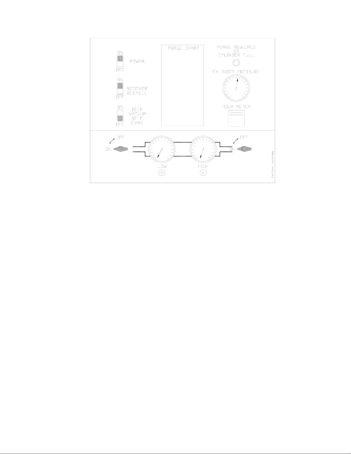
RECOVER - RECYCLE
To Recover - Recycle, refer to the above illustration and follow these steps:
1. Attach the Red and Blue Hoses to the A/C system per the manufacturer's instructions.
2. Open the High and Low Gauge Valves.
3. Open the Red and Blue Hose Valves.
4. Press the top (ON) of the rocker switch marked POWER.
5. Press the top (ON) of the rocker switch marked RECOVER-RECYCLE.
The TC670RR will automatically recover and recycle refrigerant from the A/C System until
a vacuum is sensed. This vacuum level can be seen on the Low Side Gauge.
Note: A small quantity of Liquid refrigerant will probably still remain in the A/C System. This
can be detected by observing an increasing pressure reading on the Low Pressure
Gauge. As pressure increases to a preset level, the TC670RR will automatically cycle
on and off to continue recovering refrigerant. Allow this automatic sequence to repeat
until the vacuum level remains constant for at least 2 minutes.
6. Close the Red and Blue Hose Valves.
7. Close the High and Low Gauge Valves.
8. Press the bottom (OFF) of the rocker switch marked RECOVER-RECYCLE.
9. Press the bottom (OFF) of the rocker switch marked POWER.
Note: The PURGE REQUIRED OR CYLINDER FULL light will illuminate if either the
Recovery Cylinder has filled to capacity or the pressure on the Purge Gauge
approaches 450 psig.
Page 3
Page 5

OIL DRAIN & AIR PURGE
Oil and Non-condensable Gas (Air)
are separated from the recovered
refrigerant and MUST be removed
following EACH recycling procedure
as follows:
1. SLOWLY open the Oil Drain Valve
(located on the side of the unit,
see page 7) to drain any oil which
may have been removed from the
A/C System. A plastic cup is
provided to collect the oil.
2. Close the Oil Drain Valve.
3. Determine the room temperature.
4. Locate the pressure (BARS)
corresponding to this room
temperature ( 0 C) in the chart on
the top of the TC670RR. This
chart is reproduced at the right.
5. If the pressure indicated on the
gauge is greater than that
determined from the chart...
SLOWLY open the Gas (or Vapor)
valve on the top of the Recovery
Cylinder until the gauge pressure
equals that shown in the chart.
6. Close the Gas (or Vapor) valve.
NON-CONDENSABLE PURGE CHART
(BARS)
0
C R12 R22 R502 R134a R410A R407C
0 3.03 5.45 6.34 2.90 10.27 7.38
1 3.15 5.63 6.59 3.01 10.62 7.65
2 3.28 5.79 6.76 3.10 11.00 7.86
3 3.38 6.00 6.97 3.28 11.24 8.07
4 3.52 6.34 7.24 3.45 11.58 8.34
5 3.66 6.55 7.52 3.66 11.93 8.62
6 3.79 6.76 7.76 3.81 12.27 8.76
7 3.93 6.97 8.00 3.97 12.62 9.03
8 4.07 7.18 8.22 4.12 12.89 9.24
9 4.24 7.40 8.43 4.28 13.31 9.58
10 4.41 7.66 8.76 4.41 13.72 9.93
11 4.57 7.91 9.02 4.57 14.13 10.20
12 4.73 8.17 9.28 4.73 14.55 10.48
13 4.89 8.43 9.54 4.89 14.96 10.82
14 5.05 8.69 9.80 5.05 15.51 11.10
15 5.22 8.95 10.06 5.24 15.79 11.38
16 5.38 9.21 10.33 5.42 16.13 11.65
17 5.54 9.47 10.60 5.60 16.48 12.07
18 5.70 9.73 10.88 5.79 16.96 12.41
19 5.87 9.99 11.17 5.97 17.24 12.55
20 6.07 10.34 11.66 6.34 17.79 13.03
21 6.28 10.64 11.95 6.59 18.48 13.44
22 6.48 10.94 12.25 6.83 18.96 13.79
23 6.69 11.24 12.55 7.07 19.44 14.20
24 6.90 11.59 12.90 7.31 20.06 14.48
25 7.11 11.93 13.24 7.56 20.48 14.82
26 7.31 12.28 13.59 7.80 20.89 15.03
27 7.52 12.63 13.94 8.04 21.30 15.58
28 7.73 12.98 14.29 8.28 21.72 15.99
29 7.94 13.32 14.63 8.52 22.55 16.34
30 8.14 13.79 15.10 8.76 23.24 16.75
31 8.35 14.12 15.48 9.04 23.86 17.31
32 8.55 14.44 15.86 9.32 24.48 17.79
33 8.80 14.76 16.27 9.59 25.10 18.13
34 9.05 15.14 16.67 9.87 25.58 18.55
35 9.30 15.52 17.08 10.15 26.20 19.03
36 9.55 15.89 17.49 10.43 26.75 19.44
37 9.79 16.27 17.90 10.71 27.30 19.86
38 10.04 16.65 18.31 10.99 27.99 20.27
39 10.29 17.03 18.71 11.26 28.68 20.82
40 10.62 17.59 19.24 11.52 29.37 21.30
41 10.83 18.03 19.65 11.81 30.13 21.86
42 11.08 18.47 20.06 12.09 30.89 22.48
43 11.32 18.92 20.47 12.42 31.72 22.89
44 11.60 19.38 20.91 12.77 32.27 23.37
45 11.88 19.83 21.38 13.12 32.96 23.92
46 12.16 20.29 21.85 13.47 33.78 24.48
47 12.44 20.75 22.32 13.82 34.27 24.82
48 12.73 21.20 22.80 14.16 35.09 25.44
49 13.01 21.66 23.27 14.51 35.85 25.79
50 13.29 22.12 23.74 14.86 36.89 26.06
Page 4
Page 6

VACUUM
If the A/C System is "opened" for replacing components, it is important to draw a vacuum on
the system before recharging with refrigerant. The following steps should be followed:
To Vacuum the A/C System, refer to the above illustration and follow these steps:
1. Connect the Red and Blue Hoses to the High and Low sides of the A/C System.
2. Open the Low and High Gauge Valves.
3. Open the Red and Blue Hose Valves.
4. Press the top (ON) of the rocker switch marked POWER.
5. Press the top (ON) of the rocker switch marked DEEP VACUUM-SELF EVAC.
6. The Pump will start and the TC670RR will start drawing a vacuum which will be indicated
by a dropping pressure on the Low Gauge.
NOTE: If pressure is sensed at the Red and Blue Hoses on the TC670RR, the
pump will not start, as this would result in venting of refrigerant. If this
occurs, perform the Recycle operation described earlier.
NOTE: It is normal for the TC670RR to have a 20 to 30 second discharge when
the pump is started.
4. Press the bottom (OFF) of the rocker switch marked DEEP VACUUM-SELF EVAC.
5. Press the bottom (OFF) of the rocker switch marked POWER.
6. Close the High and Low Gauge Valves.
Page 5
Page 7

SELF EVACUATION
The TC670RR can be used for different refrigerant types. The unit needs to be cleared of one
refrigerant before introducing another refrigerant. To clear (self evacuate) the TC670RR:
1. Close the hose valves on the blue and red hoses.
2. Open the High and Low Gauge Valves.
3. Press the top (ON) of the rocker switch marked POWER.
4. Press the top (ON) of the rocker switch marked RECOVER-RECYCLE.
5. The TC670RR will recover any refrigerant in the hoses and shut off when a vacuum is
sensed (the vacuum level can be seen on the pressure gauges).
6. Remove the blue hose from the low side port on the front of the unit.
7. On the rear of the unit, beside the outlet port, press the top (ON) of the rocker switch
marked RECOVERY OVERRIDE. This will allow the unit to purge the remaining refrigerant
into the DOT tank attached.
8. After approximately one minute has passed press the bottom (OFF) of the rocker switch
marked RECOVERY OVERRIDE.
Note: Unit may shut down in high pressure. If so the DOT tank attached requires purging.
Turn all switches to the OFF position and see page 3 for instructions. Once purge
processes is complete reconnect and continue with steps below.
9. Press the bottom (OFF) of the rocker switch marked RECOVER-RECYCLE.
10. Close the High and Low Gauge Valves.
11. Close the DOT tank valve where the yellow hose is connected on the rear of the TC670RR.
12. Disconnect yellow hose from the DOT tank and outlet port. Connect anti-blowback end of
yellow hose to outlet port. After connecting the remaining pressure in the system will be
released through hose. Allow pressure to completely vent to atmosphere before preceding.
13. Connect free end of yellow hose to low side port located on the front of the 670RR and
open the Low Side gauge valve.
14. Press the top (ON) of the rocker switch marked DEEP VACUUM/SELF EVAC. The
TC670RR will now self evacuate all residual refrigerant remaining in the system.
15. Run for 30 minutes.
16. Press the bottom (OFF) of the rocker switch marked DEEP VACUUM/SELF EVAC.
17. Press the bottom (OFF) of the rocker switch marked POWER.
18. Close the Low Gauge Valve.
19. Disconnect yellow hose from low side and outlet port.
20. Disconnect OFP cord from the DOT tank. Replace DOT tank with DOT tank for the new
refrigerant type. Connect OFP cord to new DOT tank.
21. Connect yellow hose end with anti-blowback to the liquid valve of the DOT tank and
connect the remaining end to the outlet port on 670RR.
22. Open liquid valve on the DOT tank.
Page 6
Page 8

SCHEDULED MAINTENANCE & FILTER MAINTENANCE
MONTHLY...
Clean the Condenser to maintain high efficiency performance of the TC670RR. Disconnect
power and remove the Compressor Compartment Cover and blow compressed air through the
cooling fins of the Condenser to remove any debris.
Do not bend the fins on the Condenser coil. Air flow will be restricted and cause damage to the
TC670RR.
Replace the Compressor Compartment Cover before applying power to the TC670RR.
PERIODICALLY AS INDICATED ON HOUR METER...
Two filters are installed on the rear of the TC670RR.
Change the long filter after every 25 hours of use (monitor the hour meter)
Change the short filter after every 50 hours of use (monitor the hour meter)
Long Filter Part Number: 026-80077-00
Short Filter Part Number: 026-80069-00
COMPRESSOR MAINTENANCE
The TC670RR is shipped from the factory filled with the correct amount of compressor oil for
initial operation.
Initial start up does not require the addition of any oil.
VERY IMPORTANT
The TC670RR requires that 2 ounces (60ml) of compressor oil be added after
every 25 hours of operation. This oil replaces the oil removed from the
compressor during normal recovery operation.
Due to this continual replenishment of oil, draining and refilling the compressor
with oil is not recommended under normal operating conditions.
Failure to add oil after every 25 hours of operation may cause a nonwarrantable compressor failure.
ADD COMPRESSOR OIL...
Remove front cover and locate add oil port on compressor. Remove cap from the port fitting and
connect short hose with depressor to fill port. Fill a syringe with two ounces of oil (RTI P/N 01180021-00). Apply power and turn the DEEP VACUUM/SELF EVAC switch to the ON position.
Insert tip of syringe in hose and inject the two ounces of oil. The vacuum will pull the oil into the
compressor. Turn the DEEP VACUUM/SELF EVAC switch to the OFF position. Disconnect
power, remove hose and install cap on port.
Page 7
Page 9

g
1
2
3
COMPONENT SETUP
5
6
7
4
TC670RR Rear Layout.dw
1 - Long Filter (026-80077-00)
2 - Anti-blowback Valve on Hose
3 - Yellow Hose
4 - Oil Drain
5 - Short Filter (026-80069-00)
6 - Power Cord
8
9
10
7 - Overfill Protection Cord (OFP)
8 - Liquid Port on DOT tank
9 - Outlet Port
10 - Recovery Override switch
Page 8
Page 10

PARTS IDENTIFICATION
P/N DESCRIPTION
1 024-80066-00 Rocker Switch (Visi-Red)
2 025-80135-00 Indicator Light (Red) 250 VAC
3 026-80071-02 High Side Gauge 0 - 500 PSIG
4 025-80002-00 Hour Meter Square 6 Digit
5 026-80065-02 Low Side Gauge 30 - 120 PSIG
6 360-80526-00 2-Way Ball Valve
7 024-80103-00 Timer INV One Shot (120V/230V)
8 025-80305-00 Solenoid Valve (230V)
9 360-81823-00 3/4 hp Compressor Assy (220V)
10 024-80037-01 Contactor 1 hp (220V) 3NO & 1NC
(120V/230V)
11 022-80126-00 Low Pressure Switch
9 PSIG - 0 PSIG
12 024-80026-02 Switch Cylinder Full
13 026-80371-00 Heated Suction Accumulator
14 022-80110-00 Automatic Expansion Valve
15 022-80105-00 High Pressure Switch
450 PSIG (220 V)
16 360-80389-00 Fan Motor Assy (220V)
16 026-80077-00 Filter 3/8 Flare (Long)
17 026-80069-00 Filter 3/8 Flare (Short)
Page 9
Page 11

FLOW DIAGRAM
January 17, 2005
570-80286-00
670RR FLOW (2004)
Page 10
Page 12

SCHEMATIC DIAGRAM
ONOFF
ONOFF
OFFON
ONOFF
January 31, 2005
670RR SCHEMATIC (2004)
570-80313-00
Page 11
Page 13

EC Declaration of Conformity for Machinery
Directive 98/37/EC
RTI Technologies, Inc.
10 Innovation Drive
York, Pennsylvania 17402 USA
Phone: 717-840-0678
Herewith declares that:
- TC670RR Refrigerant Recycling Center
- is in conformity with the provisions of the Machinery Directive (directive
98/37/EC) and with the national implementing legislation
- is in conformity with the provisions of the following other EC directives:
Electromagnetic Compatibility (EMC) Directive 89/336/EEC
Electromagnetic Emissions EN 61000-6-4: 2001
Electromagnetic Immunity EN 61000-6-2: 1999
The TC670RR is certified to the EMC Directive like the RHS780 tested by:
TÜV America Inc.
1775 Old Highway 8 NW Ste. #104
New Brighton, MN 55112
Phone: 651-638-0262
Thomas L. Crandall
Vice President - Technology
Dated: February 22 10, 2005
Page 12
 Loading...