

Page 1
OPERATION
MANUAL
RRC770 - UNDP
Refrigerant Management Center
(Convertible For Use With R12 or R134a)
RTI Technologies, Inc.
10 Innovation Drive
York, Pennsylvania 17402 USA
Phone: 717-840-0678
Fax: 717-755-8304
www.rtitech.com
035-81297-00
Page 2
RTI
CONVERTIBLE
RECYCLING MACHINE
This Recycling Machine was
manufactured by RTI in compliance
with all applicable Underwriters
Laboratories (UL) and Society of
Automotive Engineers (SAE) Standards
and Specifications for Refrigerant
Recycling Equipment.
Your machine is initially configured to
recycle R12 or R134a.
An RTI Retrofit Kit is available for field
conversion of this machme to recycle
the alternate refrigerant for which it is
now configured. This kit includes
complete instructions, labels, filters,
hoses with service couplers, and
special tools required to make the
conversion.
Once converted by an RTI Authorized
Representative, a new Serial Label
(included in the kit) will be affixed to the
machine. Ths Serial Label will certify
that the machine is then in compliance
with all SAE and UL Standards and
Specifications for Equipment to recycle
the alternate refrigerant.
Page 3

TABLE OF CONTENTS
RRC770
Before Using ................................... 1
Safety Precautions .............................. 2
Pre-Charging................................... 4
Recycle Mode .................................. 6
Oil Drain & RTI Rapid Air Purge System Procedure ..... 8
Deep Vacuum & Dehydration ...................... 9
Hose Evacuation Procedure ....................... 10
Charge Mode .................................. 11
Scheduled Maintenance .......................... 13
Combo Filter Maintenance ........................ 13
Problems & Solutions ............................ 14
Flow Diagram .................................. 16
Circuit Diagram ................................. 17
Parts List ...................................... 18
Page 4

BEFORE USING THE RRC770
Check for any shipping damage.
DO NOT USE A DAMAGED UNIT.
The RRC770 should not be operated or serviced by any person who has not read all
the contents of
one
of the limitations noted herein can result in serious injury and/or property damage.
These general instructions describe normal operation and maintenance situations
encountered with the RRC770. The instructions should not be interpreted to anticipate
every possible contingency.
It
is the responsibility of the owner/user to operate the RRC770 in accordance with all
specifications
this manual. Failure to read and comply with these instructions or any
and laws which may apply.
The following pages
precedence over any specified rule listed herein, however, is the most important rule
of all:
contain rules for safe operation of the RRC770. Taking
"USE COMMON SENSE"
A few minutes spent reading these instructions can make an operator aware of
dangerous practices
others.
A regular schedule
maintained with special attention given to Hoses and Filters.
to avoid and precautions to take for his own safety and the safety of
of inspection of the RRC770 should be established and records
Page 1
Page 5
SAFETY PRECAUTIONS
! Recover, Recycle, and Charge only the refrigerant for which the machine is configured.
! Wear safety glasses and protective gloves. Refrigerant has a very low boiling point and
can cause frostbite.
! Follow the RRC770 operating procedures sequentially to avoid prematurely
disconnecting hoses or opening valves which may release refrigerant to the
atmosphere.
! Do not expose the RRC770 to moisture or operate in wet areas.
! Use the RRC770 in locations with mechanical ventilation that provides at least four air
changes per hour.
! Hoses used with the RRC770 must have shutoff devices within 12 inches of the
connection point to the system being serviced to minimize the introduction of Noncondensable Gas (Air) into the RRC770 and the release of refrigerant when being
disconnected.
! Disconnect power before performing any maintenance or service on the RRC770.
! Avoid using an extension cord with the RRC770. If necessary, use a good condition,
UL listed, 3-wire grounded, #14 AWG extension cord of the shortest possible length.
Connect the RRC770 to a properly protected, grounded receptacle. Do not over load
the circuit.
! Do not allow the RRC770 to remain unattended in the Charge Mode with power On.
The Internal Cylinder Heater will be energized creating a high pressure condition.
NEVER TURN THE CYLINDER UP-SIDE-DOWN.
DO NOT CONNECT THE RRC770 TO THE LIQUID SIDE OF ANY
A/C SYSTEM WITH A CAPACITY GREATER THAN 4 LBS.
REFRIGERANT IN A/C SYSTEMS HAVING LARGER CAPACITIES
MUST BE RECOVERED FROM THE VAPOR SIDE ONLY.
NEVER CONNECT THE RRC770 TO THE LIQUID PORT OF A
CYLINDER OF REFRIGERANT TO FILL THE RRC770 INTERNAL
CYLINDER.
FAILURE TO FOLLOW THE ABOVE MAY CAUSE THE RRC770
COMPRESSOR TO FAIL AND VOID THE WARRANTY.
Page 2
Page 6

CAUTION
Avoid breathing refrigerant or lubricant vapor or mist.
Exposure may irritate eyes, nose and throat.
If accidental system discharge occurs, ventilate work area before resuming service.
Additional health and safety information may be obtained from refrigerant and lubricant
manufacturers.
Special Considerations with R134a
R134a has been shown to be nonflammable at ambient temperature and atmospheric
pressure. However, recent tests under controlled conditions have indicated that, at
pressures above atmospheric and with air concentrations greater than 60% by volume,
R134a can form combustible mixtures.
While it is recognized that an ignition source is also required for combustion to occur, the
presence of combustible mixtures is a potentially dangerous situation and should be
avoided.
Under no circumstances should any equipment be pressure tested or leak tested with
Air/R134a mixtures. Do not use compressed air (shop air) for leak detection in R134a
systems.
Page 3
Page 7
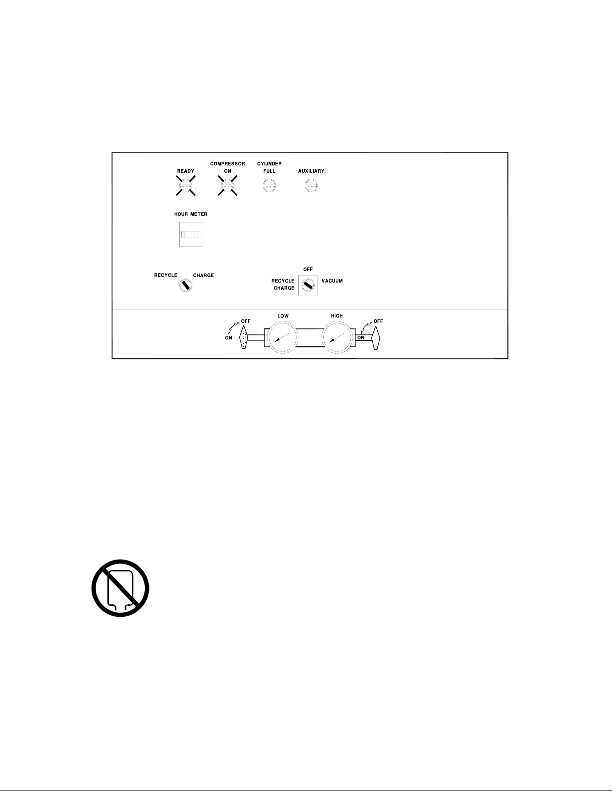
PRE-CHARGING THE RRC770
A/C Systems requiring service often do not have a full charge of refrigerant. To avoid
unnecessary repositioning of hoses it is recommended that the RRC770 be pre-charged
until about 3 pounds of liquid refrigerant can be seen in the Internal Cylinder Sight Glass.
The Sight Glass is visible through a slotted opening on the right side of the RRC770.
Figure 1 - Pre-charging
To pre-charge the RRC770, refer to Figure 1 and follow these steps:
1. Turn the Main Power Switch to Off.
2. Connect the yellow hose from the VAPOR port of a cylinder of refrigerant to the
RRC770 Access Port on the rear of the machine.
Observe that the embossed marking on the cylinder knob says VAPOR or GAS. Do
not rely on color coding of valve knobs.
DO NOT TURN THE CYLINDER UP-SIDE-DOWN.
INTRODUCTION OF LIQUID INTO THE RRC770 MAY DAMAGE
THE COMPRESSOR AND VOID THE WARRANTY.
Page 4
Page 8

3. Set Mode Selector to RECYCLE.
4. Turn Main Power Switch to RECYCLE.
The Compressor-On Light will illuminate and the RRC770 will recover and recycle
refrigerant into the Internal Cylinder. Observe the liquid refrigerant level rise in the
Internal Cylinder Sight Glass and when
at approximately 3 lbs. close the Vapor
Valve on the refrigerant cylinder.
HINT: Heating of the cylinder of refrigerant with an RTI Heat Belt (P/N 026-
80092-00) will speed the recovery process.
Allow the RRC770 to continue running until the Compressor-On Light goes off. This
will
evacuate the Yellow Hose.
5. When the Compressor-On Light goes off, turn the Main Power Switch off.
... NOTE ...
As refrigerant is processed by the RRC770, temperature variations
can cause vapor to change to liquid which may temporarily settle
in various internal components.
If a known amount of refrigerant has been introduced into the
RRC770 it may not all be seen in the Internal Charging Cylinder
Sight Glass.
This is normal and nothing to be concerned about. Refrigerant has
not been lost.
The sight glass does not indicate the amount of refrigerant
recovered. It is only accurate for determining the amount of
refrigerant charged out to the vehicle A/C System while in the
Charge Mode of operation.
Page 5
Page 9

RECYCLE MODE
Figure 2 - Recycle
To Recycle, refer to Figure 2 and follow these steps:
1. Attach Red and Blue Hoses to the A/C system per the vehicle manufacturer's
instructions.
Note For R134a Machines
Field Service Couplings on the ends of Service Hoses are of a special design.
The valves have LEFT HAND threads which makes operation opposite to that of others.
To Close.. . Turn Counter-clockwise
To Open.. . Turn Clockwise
The valves MUST BE CLOSED before connecting or disconnecting Field Service
Couplings.
2. Open High and Low Gauge Valves.
3. Open Red and Blue Hose Valves.
4. Set Mode Selector to RECYCLE.
Page 6
Page 10

5. Turn Main Power Switch to RECYCLE.
The Ready Light and Compressor-On light will illuminate. The Compressor and
Condenser Fan will be heard operating as refrigerant is recovered from the A/C
System.
The RRC770 will recover refrigerant from the A/C System until a vacuum is sensed.
The Compressor will turn off and the Compressor-On Light will turn off.
DO NOT TURN THE RRC770 OFF OR DISCONNECT HOSES
A small quantity of Liquid refrigerant will probably still remain in the A/C System. This liquid
will vaporize (boil up) and increase the pressure in the system as the components again
warm to ambient temperature. This can be detected by observing an increasing pressure
reading on the Low Side Gauge.
If pressure increases to a preset level, the RRC770 will again start to recover refrigerant.
The Compressor will turn on and the Compressor-On Light will illuminate.
Allow this sequence to repeat until the Compressor-On Light remains off continuously for
at least 2 minutes.
... NOTE ...
Several audible changes may be heard during the recovery and recycling
process.
Refrigerant flow through check valves causes a “sizzle-type" sound.
These changing "noises" are normal and nothing to be concerned about.
6. Close Red and Blue Hose Valves.
7. Close High and Low Gauge Valves.
8. Turn Main Power Switch to OFF.
CYLINDER FULL LIGHT: The Cylinder Full Light will illuminate if the Internal or External
Cylinder has been filled to capacity.
Page 7
Page 11

OIL DRAIN & RTI RAPID AIR PURGE
SYSTEM PROCEDURE
Oil and Non-condensable Gas (Air) are separated from
the recovered refrigerant and MUST be removed
following EACH recycling procedure as follows:
1. Press and hold the Purge Button (on the right side
of the RRC770) until the pressure reading on the
Pressure Gauge above this Push Button drops one
small graduation mark (approximately 5 PSIG).
2. SLOWLY open the Oil Drain Valve (Lower left side
on back of RRC770) to vent Non-condensable Gas
and drain any oil which may have been removed
from the A/C System. A plastic cup is provided to
collect the oil.
Unless the A/C System had previously been
overfilled, the RRC770 will typically not remove
enough oil to make replenishment necessary.
Leave the Oil Drain Valve open.
3. Determine the room temperature.
4. Locate the pressure (BARS) corresponding to this
room temperature (0C) in the chart to the right.
If the pressure indicated on the gauge is greater
than that determined from the chart...
Press and hold the Purge Button until the gauge
pressure equals that shown in the chart. Any Noncondensable Gas will be vented through the Oil
Drain Valve.
5. Close the Oil Drain Valve.
6. Press and hold the Purge Button for approximately
5 seconds. This permits any residual Noncondensable Gas to be re-circulated for
reprocessing during the next recycle procedure.
(BARS)
0
C R12 R134a
0 3.03 2.90
1 3.15 3.01
2 3.28 3.10
3 3.38 3.28
4 3.52 3.45
5 3.66 3.66
6 3.79 3.81
7 3.93 3.97
8 4.07 4.12
9 4.24 4.28
10 4.41 4.41
11 4.57 4.57
12 4.73 4.73
13 4.89 4.89
14 5.05 5.05
15 5.22 5.24
16 5.38 5.42
17 5.54 5.60
18 5.70 5.79
19 5.87 5.97
20 6.07 6.34
21 6.28 6.59
22 6.48 6.83
23 6.69 7.07
24 6.90 7.31
25 7.11 7.56
26 7.31 7.80
27 7.52 8.04
28 7.73 8.28
29 7.94 8.52
30 8.14 8.76
31 8.35 9.04
32 8.55 9.32
33 8.80 9.59
34 9.05 9.87
35 9.30 10.15
36 9.55 10.43
37 9.79 10.71
38 10.04 10.99
39 10.29 11.26
40 10.62 11.52
41 10.83 11.81
42 11.08 12.09
43 11.32 12.42
44 11.60 12.77
45 11.88 13.12
46 12.16 13.47
47 12.44 13.82
48 12.73 14.16
49 13.01 14.51
50 13.29 14.86
Purge Chart
Page 8
Page 12

DEEP VACUUM & DEHYDRATION
If the A/C System is "opened" for replacing components, it is important to draw a deep
vacuum on the system before recharging with refrigerant. This vacuuming process not only
removes air from the system, but just as importantly, will remove any moisture in the
system.
A Vacuum Pump in the RRC770 provides the capability of performing this "Deep Vacuum
and Dehydration". The following steps should be followed:
Figure 3 - Deep Vacuum & Dehydration Control Settings
Refer to Figure 3 for the following description of operation.
1. Connect Red and Blue Hoses to the high and low sides of the A/C System.
2. Open Low and High Gauge Valves.
3. Open Red and Blue Hose Valves.
4. Turn Main Power Switch to VACUUM.
5. The Auxiliary Light will illuminate and the RRC770 will start drawing a vacuum which
will be indicated by a dropping pressure on the Low Gauge.
NOTE... If pressure is sensed at the Red and Blue Hoses on the RRC770, the
Vacuum Pump will not start, as this would result in venting of refrigerant. The
Auxiliary Light will not be illuminated to indicate this situation.
If this occurs, turn the Main Power Switch to RECYCLE and the Mode
Selector to
RECYCLE to recover the refrigerant.
Page 9
Page 13

HOSE EVACUATION PROCEDURE
It's important that Air not be introduced into the A/C System during a Charging procedure.
If a Deep Vacuum and Dehydration procedure was performed previously, the following
Hose Evacuation Procedure is not required. If the service valves on the hoses have been
open, the following procedure must be performed:
Figure 4 - Hose Evacuation Control Settings
Refer to Figure 4 for the following description of operation.
1. Close Red and Blue Hose Valves.
2. Open High and Low Gauge Valves.
3. Turn Mode Selector Switch to RECYCLE.
4. Turn Main Power Switch to RECYCLE. The COMPRESSOR ON Light will illuminate.
5. Let the RRC770 run until the COMPRESSOR ON Light goes off.
6. Turn Low and High Gauge Valves to OFF.
7. Turn Main Power Switch to OFF. All Air has now been removed from the Hoses.
8. Vent any Non-condensable Gas as described in the previous section.
Page 10
Page 14

CHARGE MODE
Figure 5 - Charge Mode Control Settings
Refer to Figure 5 for the following description of operation:
1. Perform Hose Evacuation Procedure described previously.
2. Connect Red Hose to the A/C System per the vehicle manufacturer's instructions. Do
not open the hose valve.
3. Set Mode Selector to CHARGE.
4. Turn Main Power Switch to RECYCLE position. The Internal Charging Cylinder will
now be heating to develop pressure for charging.
5. Open High Gauge Valve. The Low Gauge Valve and both Hose Valves should be
closed.
6. Determine the refrigerant capacity of the A/C system to be charged. This data is
usually printed on a tag located on the accumulator or under the hood of the vehicle.
Convert this quantity to tenths of a pound or pounds and ounces or Kgs, if necessary,
for setting the RRC770 charge indicator.
The following will determine where to set the indicator prior to starting the charge mode:
(RRC770 Liquid Level) - (A/C System Capacity) = Indicator Setting
Page 11
Page 15

EXAMPLE: The level of liquid visible in the RRC770 Internal Cylinder Sight Glass is 7.4
lbs. and the A/C system capacity is 3.2 lbs. The following calculation results:
(7.4) - (3.2) = 4.2
Therefore, the sliding indicator should be set at 4.2 lbs. in this example. When the
liquid level lowers to the 4.2 lb. mark, a charge of 3.2 lbs. will have been delivered.
NOTE... The Sight Glass on the Charging Cylinder has markings for both R12
and R134a. Always use the correct scale for accurate charging.
7. Open Red Hose Valve. Do not start the Vehicle's Engine. Refrigerant will flow into
the high side of the A/C System. Closely monitor the liquid level as it lowers in the
Internal Cylinder Sight Glass.
8. Close Red Hose Valve as soon as the refrigerant level drops to the sliding indicator.
9. Close High Gauge Valve.
10. Turn Main Power Switch to Off.
Evacuate the hoses per the preceding section "Hose Evacuation Procedure"
The vehicle can now be started and the A/C system checked by monitoring Gauge
pressures.
Close all valves before disconnecting hoses.
NOTE: The preceding is the recommended method of charging with the RRC770.
Some vehicle manufacturers may specify connecting only to the Low Side of
the A/C System. Always follow their procedures. The above instructions
would have to be modified accordingly.
Page 12
Page 16

SCHEDULED MAINTENANCE
AFTER EVERY 10 HOURS OF OPERATION:
Clean the Condenser to maintain high efficiency performance of the RRC770. Disconnect
power and remove the Compressor Compartment Cover and blow compressed air through
the cooling fins of the Condenser to remove any debris. It may be necessary to use a soft
brush if the fins are excessively dirty.
Do not bend the fins on the Condenser coil. Air flow will be restricted and cause damage
to the RRC770. Replace the Compressor Compartment Cover before applying power to
the RRC770.
COMBO FILTER MAINTENANCE
Two Combo Filters are installed in the middle section of the RRC770.
The OUTLET Combo Filter can be identified by the presence of insulation around the
outside.
This Outlet Combo Filter must be changed after
on the Hour Meter.
The INLET Combo Filter does not have insulation around the outside. This Inlet Combo
Filter must be changed
after 25 hours operation. Hours are indicated on the Hour Meter.
50 hours operation. Hours are indicated
CHANGING THE COMBO FILTERS...
Remove Middle Section Cover to access the Combo Filters.
Disconnect Flare Adaptor Fittings at top and bottom
Remove the mounting nuts and remove Filters.
Remove the black insulation from the one filter and re-install on the
Install new Filters using the hardware removed earlier.
Connect Flare Adaptor Fittings
Check for
Replace Middle Section Cover.
leaks and repair as required.
to top and bottom of Filters.
of Filters.
new Filter.
IMPORTANT NOTE: Only the Outlet Combo Filter has a copper tube connected
to the bottom fitting. Remove the Schrader Valve from this
bottom fitting of the Outlet Combo Filter.
Page 13
Page 17

PROBLEMS & SOLUTIONS
On rare occasion the RRC770 may seem to be performing differently or not at all.
Experience has shown that varying operating conditions can affect the performance
characteristics of the RRC770. The temperature of the vehicle A/C System will affect how
the RRC770 performs.
Following are typical problems with explanations of the possible cause and solution.
PROBLEM: My RRC770 worked fine all last Summer. I got it out today for the first service
job this Spring and it is very slow in evacuating the system.
SOLUTION: Today's Spring temperature may be much lower than the average
temperatures during the summer months. Maybe the vehicle was brought in
from outside where the temperature is very low.
The refrigerant in the vehicle will not be under as high a pressure at lower
temperatures and the RRC770 will take longer to draw a vacuum. More
cycles may be required to completely recover the refrigerant.
PROBLEM: I put 5 lbs. of refrigerant into the RRC770 using the Recycle Mode. When I
checked the sight glass on the Internal Cylinder, there was less than 5 lbs.
I lost Refrigerant. The unit must leak.
SOLUTION: Due to temperature changes, some refrigerant may condense into liquid form
and stay in tubes and other components in the circuit preceding the Internal
Cylinder. This is normal and will explain why all refrigerant is not visible in the
sight glass.
PROBLEM: I can not get the RRC770 to draw a vacuum as indicated on the Low Side
Gauge.
SOLUTION: Check Hoses for restrictions.
PROBLEM: When I try to fill the Internal Cylinder from an auxiliary cylinder of clean
refrigerant, the RRC770 is really slow or shuts down.
SOLUTION: The auxiliary cylinder will cool due to the vaporization of refrigerant. This
causes the pressure to decrease.
Use a heat belt to increase the speed of recycling by the RRC770.
Page 14
Page 18

PROBLEM: I turned a 30 lb. cylinder of new refrigerant up-side-down to pre-charge the
Internal Cylinder with liquid. The Internal Cylinder didn't fill and now the
RRC770 won't recover from an A/C system.
SOLUTION: The RRC770 has been overloaded with liquid refrigerant. See Safety
Precaution Section at the beginning of this manual.
... WARNING ...
IF A CYLINDER IS TURNED UP-SIDE-DOWN, THE
RRC770 WILL OVERFILL WITH LIQUID REFRIGERANT.
THIS OVER FILLS THE SUCTION ACCUMULATOR WITH
LIQUID.
FROST ON THE OIL DRAIN ON THE REAR OF THE
RRC770 IS A GOOD INDICATION OF THIS
OCCURRENCE.
THIS SYMPTOM IS CAUSE FOR CONCERN AS LIQUID
REFRIGERANT WILL BE FORCED INTO THE
COMPRESSOR.
THIS CAN DESTROY THE COMPRESSOR AND WILL
VOID THE WARRANTY.
The safest method to remove the excess liquid which has collected in the
Suction Accumulator is to drain it from the Oil Drain on the back of the
RRC770 as follows:
Draw a deep vacuum (25 to 29 InHg) on an empty cylinder and connect it to
the Oil Drain Valve. Open the cylinder valve and the Oil Drain valve.
Close the valves and disconnect the cylinder after the liquid has been drawn
into the cylinder. This refrigerant can now be recycled by the RRC770
following normal recycling procedures.
If the above suggested solutions do not solve the problem, call 717-840-0678 and one of
our technicians will help diagnose the cause. Please have the Serial Number and hour
meter reading available for reference.
Page 15
Page 19

November 17, 2005
FLOW DIAGRAM - RRC770 - 220V - UNDP (2005)
570-80376-00
Page 16
Page 20

November 17, 2005
SCHEMATIC - RRC770 - 220V - UNDP (2005) 570-80377-00
Page 17
Page 21

Parts List
Machine Catalog Number: 460-80282-00
16
15
14
13
12
11
CR1
CR2
S14
S13
S8
S12
CR3
LPS
17
S10
HPS
M2
S22
1
1 360-80260-00 Gauge Assy 0-120 PSIG
2 022-80005-00 Relief Valve
3 360-82037-00 Charging Cylinder Assy
4 360-80748-01 Kit Sight Glass
P/N DESCRIPTION
2
3
4
5
6
7
8
5 026-80070-00 Accumulator Assembly
6 360-80369-02 D/P Switch Assembly
7 360-81307-00 High Pressure Switch - 261 PSIG
8 360-81048-01 Charging Cylinder Heater
9 360-80389-00 Fan Assy with Terms 220V
10 360-81700-01 Compressor Assy
11 026-80077-00 Combo Filter (Long)
12 026-80069-00 Combo Filter (Short)
13 025-80305-00 Solenoid (220V)
14 360-81314-00 Low Pressure Switch
10
9
Document: 560-80402-00
15 024-80037-01 Contact Relay
16 025-80127-01 Indicator Light (220V)
17 360-80076-00 Gauge Assembly 0-500 PSIG
011-80004-00 Vacuum Pump Oil - Quart
360-80359-00 Hose Gasket/Depressor Kit
Page 18
 Loading...