

Page 1

OPERATION
&
MAINTENANCE
MANUAL
RR750X
RTI Technologies, Inc.
York, PA 17402
800-468-2321
P/N 035-80052-01
Page 2

!!
!! TABLE OF CONTENTS !!
!!!!
RR750X
Before Using Page 2
Safety Precautions Page 3
Preparation For Use Page 4
Recycle Operation Page 4
Charging Capability Page 6
How The RR750X Works Page 9
Scheduled Maintenance Page 12
Problems & Solutions Page 14
Flow Diagram Page 15
Circuit Diagram Page 16
Wiring Diagram Page 17
Page 3

BEFORE USING THE RR750X
Check for any shipping damage. If damaged, place a claim with carrier.
DO NOT USE A DAMAGED UNIT.
Verify that you have received the following:
RR750X Machine
Eight Foot Refrigerant Hose (Qty=2)
Tee Fitting
Oil Syringe
Oil Drain Cup
DOT Approved Cylinder
Refrigerant Technologies, Inc.
The RR750X should not be operated or maintained by any person who has not read all the contents
of this manual. Failure to read and comply with these instructions or any one of the limitations noted
herein can result in serious injury and/or property damage.
These general instructions deal with the normal operation and maintenance situations encountered
with the RR750X. The instructions should not be interpreted to anticipate every possible
contingency.
It is the responsibility of the owner/user to operate the RR750X in accordance with all specifications
and laws which may apply.
The following pages contain rules for safe operation of the RR750X. Taking precedence over any
specified rule listed herein, however, is the most important rule of all:
"USE COMMON SENSE".
A few minutes spent reading these instructions can make an operator aware of dangerous practices
to avoid and precautions to take for his own safety and the safety of others.
A regular schedule of inspection of the RR750X should be established and records maintained with
special attention given to hoses and replaceable filters.
May 24, 1993 Page 2
Page 4

Refrigerant Technologies, Inc.
SAFETY PRECAUTIONS
! Wear safety glasses and protective gloves. Refrigerant has a very low boiling point and can cause
frostbite.
! Follow the RR750X operating procedures sequentially to avoid prematurely disconnecting hoses
or opening valves which may release refrigerant to the atmosphere.
! Do not expose the RR750X to moisture or operate in wet areas.
! Use the RR750X in locations with mechanical ventilation that provides at least four air changes
per hour or locate the unit 18 inches above the floor.
! Service hoses used with the RR750X must have shutoff devices within 12 inches of the
connection point to the system being serviced to minimize the introduction of non-condensable
gases into the recovery unit and the release of refrigerant when being disconnected.
! Disconnect power before performing any maintenance or service on the RR750X.
! Avoid using an extension cord with the RR750X. If necessary, use a good condition, UL listed,
3-wire grounded, #14 AWG extension cord of the shortest possible length.
! Do not introduce refrigerant in the liquid state into the RR750X from any source having greater
than a 4.5 lb. capacity. Steady introduction of large amounts of liquid refrigerant may cause the
RR750X to malfunction.
! Connect RR750X to grounded and protected 115 VAC - 60 HZ power source.
! Recover R-12 refrigerant only.
May 24, 1993 Page 3
Page 5
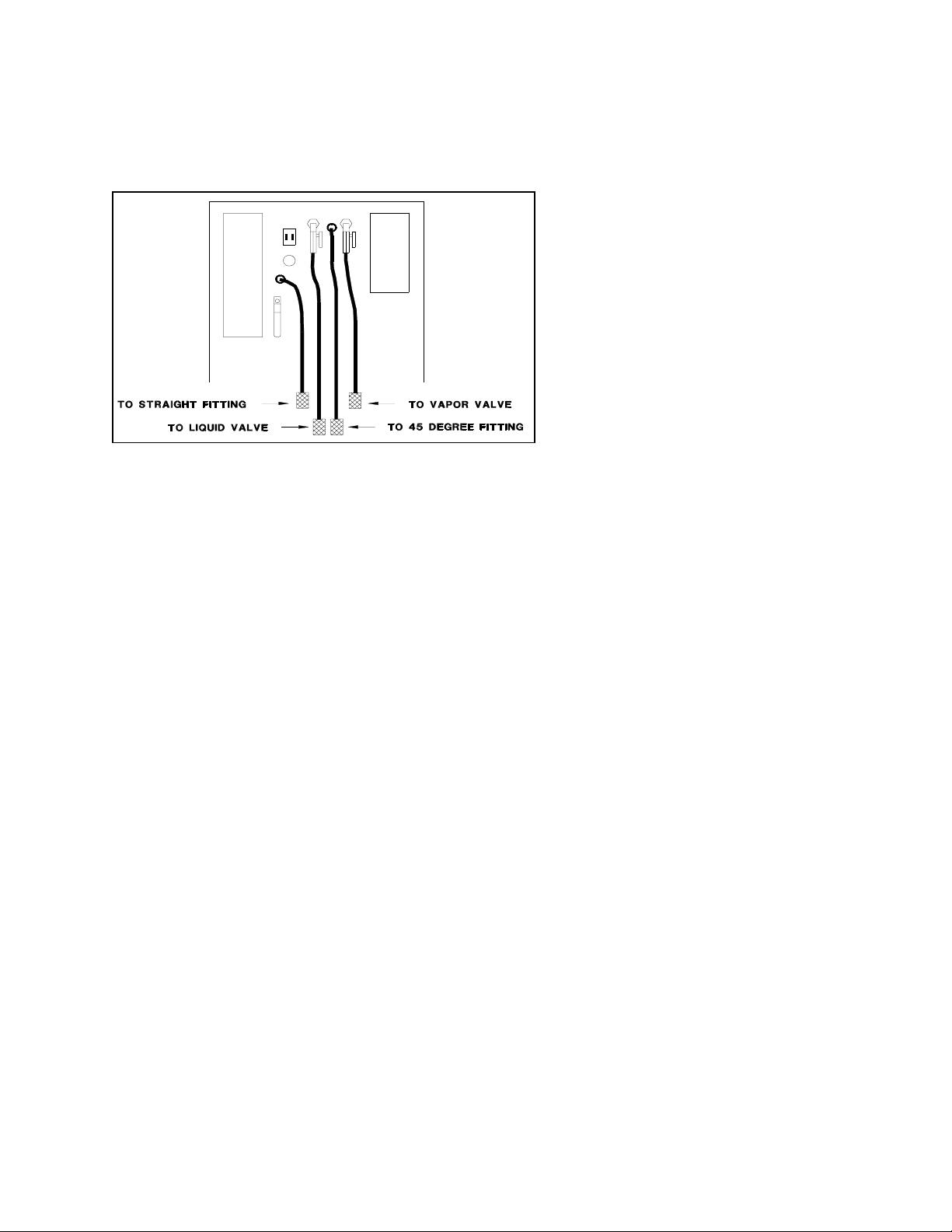
PREPARATION FOR USE
Figure 1 Hose Connections
Refrigerant Technologies, Inc.
Place the External Cylinder on the
Weight Scale Platform on the rear of
the RR750X.
Connect the four hoses to the External
Cylinder as shown in Figure 1.
NOTE:
Color standards for cylinder valve
knobs were changed by the
manufacturer during 1992.
Therefore, do not depend on color to
indicate liquid or vapor valves on the
External Cylinder. Look for
“LIQUID” or “VAPOR” embossed
on the knobs.
Tighten fittings FINGER-TIGHT only. Over tightening may cause damage to the fittings or valves
and result in leaks.
It is recommended that ALL connections be checked with an electronic leak detector each time hoses
are reconnected.
RECYCLE OPERATION
Set valves on the RR750X as follows in preparation for performing a Recover/Recycle operation:
! Red Valve on External Cylinder OPEN (Counter-clockwise)
! Blue Valve on External Cylinder OPEN (Counter-clockwise)
! Ball Valve on Red Hose OPEN (Handle parallel to hose)
! Ball Valve on Blue Hose OPEN (Handle parallel to hose)
! Yellow Filter Bypass Valve OFF (Handle vertical)
May 24, 1993 Page 4
Page 6

Refrigerant Technologies, Inc.
Connect one end of the 8 Ft. yellow hose to the Inlet Port of the RR750X. Connect the other end to
the center port of a Gauge Manifold. The hose can also be connected directly to the low side of the
vehicle A/C system. The Pressure Gauge on the RR750X can then be used to monitor pressure.
If using a Gauge Manifold, connect it to the A/C system as specified by the manufacturer of the
vehicle.
Open the Gauge Manifold Valves (Counter-clock-wise).
NOTE: It is recommended that the High and Low Gauge Manifold Hoses have shut-off devices
within 12 in. of the ends connected to the vehicle A/C system. This will permit the
recovery of refrigerant from the hoses.
The yellow Service Hose could be connected directly to the low side of the A/C System
and the RR750X Inlet Pressure Gauge used to monitor pressure.
Turn the Main Power Switch to On.
The Ready Light and Compressor-On light will illuminate. The Compressor High Pressure Light
will flash momentarily. The Compressor and Condenser Fan will be heard operating as refrigerant
is recovered from the vehicle.
NOTE: Several audible changes may be heard during the recovery process. The oil
re-circulation and non-condensable gas venting circuits will cycle
periodically.
Refrigerant flow through check valves causes a "sizzle-type" sound.
These changing "noises are normal and nothing to be concerned
about.
The RR750X will recover refrigerant from the A/C system. The Compressor-On Light will then turn
off.
!!!! DO NOT TURN THE RR750X OFF OR DISCONNECT HOSES !!!!
A small quantity of Liquid refrigerant will probably remain in the A/C system of the vehicle. This
liquid will vaporize as the system components again warm to ambient temperature. This can be
detected by noticing an increase in pressure readings on the Gauge Manifold.
May 24, 1993 Page 5
Page 7

Refrigerant Technologies, Inc.
If the pressure increases to a preset level, the RR750X will again start to recover refrigerant. The
Compressor will turn on and the Compressor-On Light will illuminate.
Allow this sequence to repeat until the Compressor-On Light remains off continuously for 2 minutes.
Close the valves on the 8 Ft. hose and the Gauge Manifold.
Turn the Main Power Switch to OFF.
Slowly open the Oil Drain Valve on the back of the RR750X to drain any oil which may have been
removed from the A/C system. Use the cup provided to measure the amount of oil which was
removed during the recovery procedure. Refer to the A/C system manufacturer's manual for
recommendations concerning the need to add lubrication during the charging procedure.
Hoses can now be disconnected and the A/C system serviced.
CHARGING WITH THE RR750X
Refrigerant is recycled by the RR750X and stored in the External Cylinder. An Accessory Charging
Cylinder or Auxiliary Charging Tank with a Weighing Scale can be used to charge an A/C System
with this recycled refrigerant.
Refer to Figure 1 to determine which hose on the back of the RR750X is connected to the External
Cylinder “LIQUID” Valve.
Disconnect this hose from the External Cylinder and install the Liquid Line Tee Tap supplied with
the RR750X.
Connect one end of the Yellow Service Hose to the Tee. Make all connections finger tight only.
Refer to Figures 2 and 3 for connection configurations to transfer refrigerant from the RR750X
External Cylinder to a Charging Cylinder or Auxiliary Charging Tank.
Pressure in a Charging Cylinder or Auxiliary Charging Tank must be less than the pressure in the
RR750X External Cylinder. The RR750X can be used to create this pressure differential without
releasing refrigerant to the atmosphere as follows:
Connect the Yellow Service Hose from the Inlet Port of the RR750X to the Vapor Port of the
RR750X to the Vapor Port of a Charging Cylinder or Auxiliary Charging Tank.
Open ball valve on the Yellow Service Hose.
MOMENTARILY (10 to 15 Seconds) turn the RR750X Power Switch On.
Close ball valve and reconnect the Yellow Service Hose for transferring liquid from the RR750X
External Cylinder (Refer to Figures 2 and 3).
May 24, 1993 Page 6
Page 8

Refrigerant Technologies, Inc.
The Charging Cylinder or Auxiliary Tank can now be filled and used to charge the A/C System
according to the Manufacturer’s instructions.
A pressure differential is required to encourage flow of refrigerant into the A/C System.
Some Charging Cylinders have a heating element for the purpose of creating this differential in
pressures.
Mild heating of the Auxiliary Tank will develop this pressure differential. Immersion in warm
water is the least risky method.
... CAUTION ...
CONSULT THE CHARGING CYLINDER OR WEIGHT SCALE INSTRUCTIONS FOR
SAFE OPERATING PROCEDURES.
CARELESS OPERATION MAY RESULT IN A DANGEROUS CONDITION CAUSED BY
OVERFILLING THE CHARGING CYLINDER OR AUXILIARY TANK.
DO NOT EXCEED THE MAXIMUM RATED PRESSURE OF A CHARGING CYLINDER
OR AUXILIARY TANK.
CAREFULLY MONITOR THE LIQUID LEVEL OF REFRIGERANT IN THE CHARGING
CYLINDER OR WEIGHT OF AUXILIARY TANK DURING A FILL PROCEDURE.
OVERFILLED CHARGING CYLINDERS OR AUXILIARY TANKS MAY DAMAGE THE
RR750X COMPRESSOR DURING THE MOMENTARY PRESSURE DIFFERENTIAL
PROCEDURE AND VOID THE WARRANTY!
May 24, 1993 Page 7
Page 9

Refrigerant Technologies, Inc.
Figure 2 Using the RR750X to Charge with Charging Cylinder
Figure 3 Using the RR750X to Charge with Auxiliary Charging Tank
May 24, 1993 Page 8
Page 10

Refrigerant Technologies, Inc.
HOW THE RR750X RECOVERS & RECYCLES REFRIGERANT
Following is a description of the purpose and performance characteristics of the components within
the RR750X. The items are discussed in the order as seen by refrigerant as it flows through the unit
from the Inlet Port to the External Cylinder.
Refer to the Flow Diagram and Circuit Diagram in the Appendix.
INLET PRESSURE GAUGE
Indicates pressure of refrigerant at the Inlet Port of the RR750X.
CHECK VALVE
Prevents escape of refrigerant to the atmosphere.
SUCTION ACCUMULATOR
This device may be designated by several different names, the most common being:
! SUCTION ACCUMULATOR
! SUCTION RECEIVER
! SUCTION OIL SEPARATOR
Vapor and/or saturated liquid refrigerant from the vehicle A/C system enters the Suction
Accumulator through the Inlet Port.
Refrigerant still in the liquid state will vaporize in the Suction Accumulator due to the increase in
volume.
As the refrigerant changes direction of travel while flowing through the Suction Accumulator, oil
droplets (with greater mass than the refrigerant vapor) are slung towards the container walls where
they collect and migrate to the bottom.
This oil is removed from the Suction Accumulator through the Oil Drain Valve and measured after
each recovery cycle to determine the need to add oil to the A/C system.
The Low Pressure Switch mounted on the Suction Accumulator opens when a vacuum of 8 ± 2 In.
Hg. is detected. This stops the recovery process. This switch closes again when a pressure greater
than 3 ± 3 PSIG is reached.
ACID FILTER
Refrigerant enters the Acid Filter through a port on the top and travels through a solid desiccant core
where organic and volatile contaminates are filtered, moisture is absorbed, and acid is removed. The
refrigerant travels from the outside to the inside of the desiccant core and then out through the
bottom port.
May 24, 1993 Page 9
Page 11

Refrigerant Technologies, Inc.
Refrigerants react with water to form hydrochloric and hydrofluoric acids which are corrosive to
equipment and contaminate oil. Removal of acid at this stage is important to protect the Compressor
and other RR750X components.
The Acid Filter must be replaced after every 500 hours of operation.
CHECK VALVE (1 PSI)
The Check Valve permits forward refrigerant flow when the output pressure from the Acid Filter is
1 lb. or greater than pressure at the output side of the Check Valve. The primary purpose of this
check valve is to prevent flow of oil backwards towards the Acid Filter during the Oil Return Cycle
from the Oil Separator.
SUCTION SHUTDOWN SOLENOID VALVE S-11
Prevents flow of refrigerant to the Compressor when not operating.
SUCTION PRESSURE REGULATING VALVE
This valve is sensitive only to the pressure at the outlet port. The pressure range at which the valve
is open is increased or decreased by adjusting a spring which acts on an internal bellows.
Inlet pressure to the valve is exerted on the bellows and the top of the seat disk. Since the effective
areas of the bellows and seat disk are equal, the inlet pressure has no affect on the valve operation.
The output pressure of the valve acts on the underside of the seat disk and exerts a pressure in the
closing direction. This force is opposed by a spring which is adjusted to set the pressure at which
the valve closes.
During production of the RR750X, this valve is adjusted to limit the mass flow rate to 10 ± 2 PSIG
during normal operation.
COMPRESSOR
Refrigerant is compressed, resulting in an increase of temperature. This temperature rise is due to
the total heat of the vapor being squeezed into a smaller space.
The compression of gaseous refrigerant in a compressor is considered to be near a state of Adiabatic
Compression. Adiabatic refers to the process whereby a gas is compressed (or expanded) without
any transfer of heat into it during the compression (or expansion).
A very slight increase in temperature may be due to frictional heat generated within the Compressor.
A sight tube is mounted on the Compressor for monitoring the oil level. The Maintenance Section
of this manual describes procedures for adding oil as required.
May 24, 1993 Page 10
Page 12

Refrigerant Technologies, Inc.
HIGH PRESSURE SWITCH
The High Pressure Switch opens-on-rise at a pressure of 261 ± 7 PSIG and closes on-fall at 203 ±
7 PSIG. The Compressor turns off and Solenoid Valve S11 closes to prevent flow of refrigerant
through the system.
OIL SEPARATOR
Filtering of the refrigerant to remove oil is accomplished by a fine composition filter element.
Refrigerant enters through the top of the canister to the inside of the element, passes through the
element towards the outside, and then exits from the bottom of the canister.
The removal of oil is important to prevent clogging the Filter-Drier which removes moisture from
the refrigerant.
CHECK VALVE (5 PSI)
The Check Valve permits forward refrigerant flow when pressure from the outlet of the Oil Separator
is 5 lbs. or more than the outlet pressure of the Check Valve.
FILTER BY-PASS VALVE
Manual operation of 3-way Filter By-Pass Valve facilitates purging refrigerant from the filters prior
to their removal. Operation of this valve is described in the Maintenance Section of this manual.
FILTER-DRIER
Refrigerant enters the top of the canister and flows through a perforated plate and then through
moisture absorbing desiccant. Moisture removal is very important due to the formation of acids
which result when water and refrigerant are allowed to mix.
The Filter-Drier must be changed after every 75 hours of operation.
CONDENSER (COOLED BY FAN)
The high temperature, high pressure refrigerant vapor is cooled by air moving over the finned
Condenser. The vapor condenses into liquid form as it is cooled.
EXTERNAL CYLINDER
Refrigerant flows to the External Cylinder until the weight switch shuts the RR750X off due to a full
cylinder.
DIFFERENTIAL PRESSURE SWITCH (DPS)
The venting of non-condensable gases (Air) is performed by the DPS Assembly. A refrigerant/Air
mixture will exhibit a higher pressure than pure refrigerant. Pressure inside a sealed bulb of pure
refrigerant is compared to the refrigerant/Air mixture at the External Cylinder at equal temperatures.
When the Air concentration in the Internal Cylinder reaches a preset amount, the DPS activates the
Non-condensable Gas Discharge Solenoid (S8). The Air is slowly vented until the pressures again
equalize.
May 24, 1993 Page 11
Page 13

Refrigerant Technologies, Inc.
SCHEDULED MAINTENANCE
DAILY BEFORE USE...
Check the oil level in the Compressor daily before operating the RR750X.
The oil level tube can be seen next to the Compressor by looking through the vent openings on the
side of the RR750X nearest the Main Power Switch.
Oil should be visible in the clear tube, but at a level less than one inch.
If the oil level is not visible, proceed with the Recover/Reclaim operation and recheck the oil level
when complete.
If the level is still not visible, oil must be added.
Remove the front cover. Slowly remove the Oil Fill Cap on the Compressor. Allow the pressure
to equalize.
Use the Oil Syringe to add Refrigeration Oil until the level is visible and less than one inch. Add
one syringe full at a time. Wait 5 minutes between each syringe full for the oil to settle.
THE OIL LEVEL MUST NEVER BE MORE THAN ONE INCH HIGH
Replace the Oil Fill Cap on the Compressor before applying power to the RR750X.
AFTER EVERY 10 HOURS OF OPERATION...
Clean the Condenser to maintain high efficiency performance of the RR750X. Remove both side
covers and blow compressed air through the coil to remove any debris. It may be necessary to use
a soft brush if the coil is very dirty.
Do not bend the fins on the Condenser coil. Air flow will be restricted and cause damage to the
RR750X. Replace both side covers before applying power to the RR750X.
AFTER EVERY 75 HOURS OF OPERATION
Replace Filter-Drier as described in the following steps:
! Turn on Filter By-pass Valve by turning yellow handle on rear of cabinet to HORIZONTAL
position.
! Remove larger filter cover on rear of cabinet.
! Remove cap on access fitting of Filter-drier and connect 8 Ft. hose from this fitting to the Inlet
Port of the RR750X.
! Turn on the Main Power Switch and recover all the refrigerant from the Filter-drier.
! Remove and replace the Filter-drier. Reuse the black insulation around the filter. Disposal
of old filter requires no special handling as it contains no hazardous substances.
MAKE ALL CONNECTIONS FINGER-TIGHT ONLY
May 24, 1993 Page 12
Page 14

Refrigerant Technologies, Inc.
USE CAUTION TO NOT MOVE CONNECTING TUBES AS LEAKS COULD DEVELOP
! Turn off Filter By-pass Valve by turning yellow handle on rear of cabinet to VERTICAL
position.
! Operate the RR750X in Recover Mode and check for leaks. Repair as necessary.
! Record Hour Meter reading on label provided. Replace the Filter-drier cover.
AFTER EVERY 500 HOURS OF OPERATION
Replace Acid Filter as described in the following steps:
! Cap the RR750X Inlet Port.
! Turn on the Main Power Switch and allow RR750X to run until Compressor-On Light goes
off.
! Turn off the Main Power Switch.
! Remove the smaller filter cover on rear of cabinet.
! Remove and replace the Acid Filter. Note direction of flow indicated on the new Acid Filter.
The arrow must point DOWN.
! Operate the RR750X in Recover Mode and check for leaks. Repair as necessary.
! Record Hour Meter reading on label provided. Replace the Acid Filter cover.
May 24, 1993 Page 13
Page 15

Refrigerant Technologies, Inc.
PROBLEMS & SOLUTIONS
On rare occasion the RR750X may seem to be performing differently or not at all. Experience has
shown that varying operating conditions can affect the performance characteristics of the RR750X.
The temperature of the vehicle A/C System will affect how the RR750X performs.
Following are typical problems with explanations of the possible cause and solution.
PROBLEM: My RR750X worked fine all last Summer. I got it out today for the first service job
this Spring and it is very slow in evacuating the system.
SOLUTION: Today's Spring temperature may be much lower than the average temperatures
during the summer months. Maybe the vehicle was brought in from outside where
the temperature is very low.
The refrigerant in the vehicle will not be under as high a pressure at lower
temperatures and the RR750X will take longer to draw a vacuum. More cycles may
be required to completely recover the refrigerant.
PROBLEM: I used the RR750X to service an A/C system earlier today and it worked great. This
afternoon it won't recover. The Compressor-On Light doesn't even come on.
SOLUTION: The pressure switch on the Suction Accumulator has a close-on-rise setting of 3 ±
3 PSIG. If there is less than 6 PSIG of refrigerant pressure in the vehicle's A/C
System, the RR750X may fail to start.
Connect a source of refrigerant pressure (for example, the External Cylinder) to the
Inlet Port of the RR750X. This will reset the pressure switch so the RR750X will
run when reconnected to the vehicle A/C. It will continue until a vacuum is
achieved.
PROBLEM: I can not get the RR750X to draw a vacuum.
SOLUTION: Connect the Gauge Manifold to the Oil Drain Valve on the RR750X. Close the Inlet
Port and, with the unit running in Recover/Reclaim Mode, determine if a vacuum
can be drawn. If yes, check the charging hoses and Gauge Manifold for possible
obstructions.
May 24, 1993 Page 14
Page 16

Refrigerant Technologies, Inc.
May 24, 1993 Page 15
Page 17

Refrigerant Technologies, Inc.
May 24, 1993 Page 16
Page 18

Refrigerant Technologies, Inc.
May 24, 1993 Page 17
 Loading...