

Page 1

OPERATION
&
MAINTENANCE
MANUAL
750-SP1 UNDP
RTI Technologies, Inc.
4075 East Market Street
York, Pennsylvania, 17402 USA
Phone: 717-840-0678
Fax: 717-755-8304
www.rtitech.com
rti@rtitech.com
Manual P/N 035-80928-00
Page 2

TABLE OF CONTENTS
Before Using & Safety Precautions ............. 2
Preparing the Outlet Cylinder ................. 3
Setting Up the 750-SP1 to Recycle ............. 4
Recycling Refrigerant ....................... 5
When Inlet Cylinder is Empty ................. 6
Removing Air from Outlet Cylinder .............7
Pressure - Temperature Table ................ 8
Scheduled Maintenance ..................... 9
Flow Diagram ............................. 10
Circuit Diagram ............................ 11
Page 3

BEFORE USING
SAFETY PRECAUTIONS
Check for any shipping damage. Place a
claim with carrier if damage is discovered.
DO NOT USE A DAMAGED UNIT.
The machine should not be operated or
serviced by any person who has not read
all the contents of this manual. Failure to
read and comply with these instructions or
any one of the limitations noted herein
can result in serious injury and/or property
damage.
These general instructions describe
normal operation and maintenance
situations encountered. The instructions
should not be interpreted to anticipate
every possible contingency.
It is the responsibility of the owner/user to
operate the machine in accordance with
all specifications and laws which may
apply.
The following pages contain rules for safe
operation. Taking precedence over any
specified rule listed herein, however, is
the most important rule of all:
! Recover, Recycle, and Charge only
the refrigerant for which this machine
is configured.
! Wear safety glasses and protective
gloves. Refrigerant has a very low
boiling point and can cause frostbite.
! Follow operation procedures
sequentially to avoid prematurely
disconnecting hoses or opening
valves which may release refrigerant
to the atmosphere.
! Do not expose the machine to
moisture or operate in wet areas.
! Use the machine in locations with
mechanical ventilation that provides at
least four air changes per hour.
! Hoses have shutoff devices within 30
mm of the connection point to the
system being serviced to minimize the
introduction of Non-condensable Gas
(Air) into the machine and the release
of refrigerant when being
disconnected.
"USE COMMON SENSE"
A few minutes spent reading these
instructions can make an operator aware
of dangerous practices to avoid and
precautions to take for his own safety and
the safety of others.
A regular schedule of inspection should
be established and records maintained
with special attention given to Hoses and
Filters.
! Disconnect machine from power
before performing any maintenance or
service.
! Avoid using an extension cord. If
necessary, use a good condition, 3wire grounded, 2.5 mm
cord of the shortest possible length.
2
extension
! Connect the machine to a properly
protected, grounded receptacle. Do
not over load the circuit.
! Do not allow the machine to remain
unattended in the Charge Mode with
power On. The Internal Cylinder
Heater will be energized creating a
high pressure condition.
Page 2
Page 4
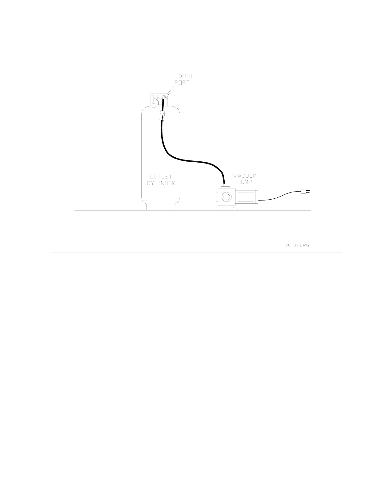
PREPARING THE OUTLET CYLINDER
1. Connect one end of a Yellow Hose to the Liquid Port of the Outlet Cylinder.
2. Connect other end of the Yellow Hose to a Deep Vacuum Pump.
3. Close Vapor Valve.
4. Open Liquid Valve and valve on Yellow Hose.
5. Connect Vacuum Pump to power source.
6. Draw a vacuum on the Outlet Cylinder for one hour.
7. Close Outlet Cylinder Liquid Valve and valve on Yellow hose.
8. Disconnect Yellow Hose from Vacuum Pump and connect to rear access port of the 750-SP1.
Page 3
Page 5

SETTING UP THE 750-SP1 TO RECYCLE
1. Connect Pressure Gauge to Vapor Port of Outlet Cylinder.
2. Position Inlet and Outlet Cylinders as shown.
3. Connect OFP Cord to Receptacle on Outlet Cylinder.
4. Connect Yellow Hoses to Inlet and Outlet Cylinders.
5. Open valves on both Yellow Hoses.
6. Open Liquid Valve on Inlet Cylinder and Liquid Valve on Outlet Cylinder.
7. Connect Power Cord to proper voltage supply.
Page 4
Page 6

RECYCLING REFRIGERANT
1. Set Mode Selector to RECYCLE.
2. Set Main Switch to RECYCLE/CHARGE. The READY Light will be on.
3. Set Access Valve to RECYCLE. The COMPRESSOR-ON light will be on and the 750-SP1 will
begin recovering refrigerant from the Inlet Cylinder. The 750-SP1 is specially designed to
process Liquid or Vapor refrigerant.
Refrigerant will be purified by the 750-SP1 and collected in the Internal Cylinder.
When the Internal Cylinder fills to capacity, the 750-SPl will automatically stop recovering from
the Inlet Cylinder. The CYLINDER FULL Light will be on and the COMPRESSOR-ON Light
will be off.
A timer will activate and the 750-SP1 will automatically charge refrigerant from the Internal
Cylinder to the Outlet Cylinder.
At the end of the timed charge the 750-SP1 will begin recovering refrigerant.
Page 5
Page 7

WHEN INLET CYLINDER IS EMPTY
The 750-SP1 will recover and recycle refrigerant from the Inlet Cylinder until it is empty. When all
of the refrigerant has been recovered and recycled, the COMPRESSOR-ON light will be off and
the 750-SP1 will automatically shut off.
Oil which has been removed from the refrigerant must be drained from the 750-SP1 as follows.
This procedure MUST be performed after emptying each Inlet Cylinder.
1. Set Main Switch to OFF.
2. Press and hold the Purge Button (Right side of machine) until the pressure on the Pressure
Gauge above the Purge Button drops one small graduation mark (approximately 5 PSIG).
3. SLOWLY open Oil Drain Valve (Lower left side on rear of machine) and drain any oil which
may have been removed from the refrigerant. A plastic cup is provided to collect the oil.
4. Close the Oil Drain Valve.
Page 6
Page 8

REMOVING AIR FROM OUTLET CYLINDER
The Pressure Gauge mounted on the Vapor Port of the Outlet Cylinder should be checked
periodically for an indication of excessive Air. The end of the Tee Fitting to which the Pressure
Gauge is attached must be capped. All Valve Cores, if any, must be removed from the Tee Fitting.
Open the Vapor Valve on the Outlet Cylinder to read the pressure in the cylinder.
Measure the ambient temperature and find the corresponding pressure for that temperature in the
following Pressure-Temperature Table.
If the Pressure Gauge reading is greater than the pressure determined from the table, the excess
air should be vented from the Outlet Cylinder as follows:
1. Close the Vapor Valve on the Outlet Cylinder.
2. Remove the cap from the Tee Fitting.
3. Slowly open the Vapor Valve to release Air until the Pressure Gauge reads the same as the
temperature determined from the table.
4. Close the Vapor Valve and replace cap on the Tee Fitting.
EXCESSIVE PRESSURE DUE TO AIR IN THE OUTLET CYLINDER WILL CAUSE THE 750-SP1
TO SHUT DOWN IN A "HIGH PRESSURE" CONDITION OR REFRIGERANT MAY NOT FLOW
FROM THE 750-SP1 TO THE OUTLET CYLINDER.
Page 7
Page 9

Page 8
Page 10

SCHEDULED MAINTENANCE
MONTHLY
Clean the Condenser to maintain high efficiency performance. Disconnect power and remove
the Compressor Compartment Cover and blow compressed air through the cooling fins of the
Condenser to remove any debris. It may be necessary to use a soft brush if the fins are
excessively dirty.
Do not bend the fins on the Condenser coil. Air flow will be restricted and cause damage to the
machine. Replace the Compressor Compartment Cover before applying power.
COMBO FILTER & FILTER-DRIER
Replace the Combo Filter and Filter-Drier after every 75 Hours of operation.
Combo Filter P/N: 026-80077-00
Filter-Drier P/N: 026-80044-00
To replace the Filters:
1 Disconnect machine from power.
2 Remove the Middle Cabinet Cover.
3 Locate the Filters mounted on a bracket on the left side of the machine. The Filter-Drier
has black insulation wrapped around it.
3.1 Disconnect Flare Fittings at top and/or bottom of Filters.
3.2 Remove mounting hardware and remove Filters.
3.3 Remove the black insulation and install on new Filter-Drier.
3.4 Install new Filters using hardware removed earlier.
3.5 Connect Flare Fittings to top and/or bottom of Filters.
4 Check for leaks and repair as required.
5 Replace Middle Cabinet Cover.
Page 9
Page 11

Page 10
Page 12

Page 11
 Loading...