

Page 1
®
RHS
980/980H
Operation Manual
10 Innovation Drive
York, Pennsylvania 17402 USA
Phone: 717-840-0678
Toll Free: 800-468-2321
Web-site: www.rtitech.com
MAHLE Clevite Inc., RTI Division
Manifold Protected Under US Pat No. 7,726,343
Manual P/N: 035 81589 00 (REV J)
Page 2

CONGRATULATIONS
You have purchased the finest Recovery,
Recycling and Charging Machine certified to SAE
Standard J2788!
Fill out and return the Warranty Card within 90
days to activate warranty and free lifetime
technical support.
1
Page 3

TABLE OF CONTENTS
Introduction ...................................................................................................... 4
Overview of the RHS980 and How to Operate it ............................................. 5
Startup & Safe Operation ................................................................................ 6
Special Considerations with R134a ................................................................. 6
Control Panel ................................................................................................... 7
First Time Use ................................................................................................. 8
Contaminated Refrigerant .............................................................................. 10
Automatic Operation ....................................................................................... 11
Printing Results .............................................................................................. 16
Oil Flush – Hybrid Service .............................................................................. 17
Setup .............................................................................................................. 19
Selectable Options .................................................................................... 19
Select Language
Enable Buzzer
Enable Refrigerant Identifier
Enable A/C Capacity Database
Enable Printer
Enable Print to Flash Drive
Enable Low Voltage Detect
Enable Micron Vacuum Sensor
Enable Password Protection
Enable VIN Entry
Enable Operator ID Entry
Enable AC Test Mode
Enable Vacuum Pump Oil Life Test
Enable Refrigerant Liquid Flush
Enable Tech Alert Demo
Enable High Pressure Leak Detect
Enable Automatic Weighing Oil Injection
Enable Automatic Weighing Oil Drain
Enable Automatic Weighing UV Dye
Enable High Voltage Oil Flush
Enable Fill Cylinder
Enable Manual Oil Injection
Default Values ........................................................................................... 22
Fill Cylinder Target Amount
Initial Vacuum Hold Level
Final Vacuum Level
Vacuum Run Time
Hoses Overcharge Amount
Minimum Line Voltage
Elevation from Sea Level
Vacuum Pump Oil Life Rise Level
2
Page 4

TABLE OF CONTENTS Continued
Oil Drain Maximum Level
Minimum Vacuum Leak level
High Voltage Flush
Maintenance Options ................................................................................ 24
Calibration Check
Perform Load Cell Site Calibration
Perform Load Cell Shop Calibration
Set Date and Time
Input/Output Diagnostics
Combo Filter Replacement
Vacuum Pump Oil Replacement
Change Operator Passwords
Change Service Manager Password
Print Parameters
Total Capacities .............................................................................................. 29
Combo Filter Life Remaining
Total Refrigerant Recycled
Total Refrigerant Charged
Vacuum Pump Oil Life Remaining
Reminders ................................................................................................. 30
Scale Calibration
Calibration Check
Tech Alert Demo Mode ............................................................................ 30
Vacuum Pump Maintenance ..................................................................... 32
Combo Filter Maintenance ........................................................................ 32
Inline Filter Maintenance ........................................................................... 33
Printer Maintenance .................................................................................. 34
Refrigerant Identifier Maintenance ............................................................ 34
Updating Program, Languages and Configuration Files ........................... 35
Frequently Used RTI Consumable Items .................................................. 36
Parts Identification ..................................................................................... 37
Notes……… .............................................................................................. 38
TechALERT ............................................................................................... 40
3
Page 5
INTRODUCTION
r
RTI RHS980 Refrigerant Handling System is designed for use on R134a vehicles and is compliant with J2788
standard. Unit recovers 95% of automobile refrigerant systems and has a refrigerant recharge accuracy of +/- ½
ounce. It features fully automatic operation. All control functions of the RHS980 are designed to provide intuitive
and rapid interaction with the service technician. Easily removable one piece composite cover allows gaining
unobstructed access to all interior components for service and maintenance.
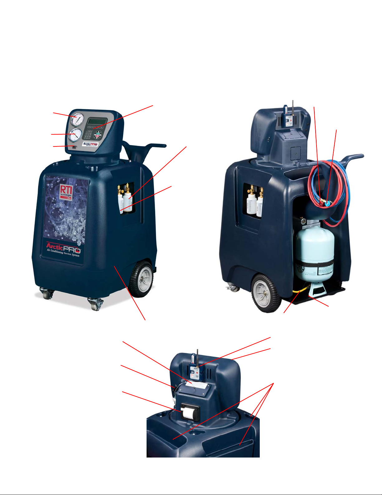
Images below show the key features of RHS980 Refrigerant Handling System.
High Pressure
Gauge
Low Pressure
Gauge
Power Switch
Control Panel with
LCD Display
Oil Drain Bottle
and O-ring
Oil Fill Bottle
Not included on unit
configured for High
Voltage Oil Flush
High Side Service
Hose with Coupler
Low Side Service
Hose with Coupler
New Refrigerant
Removable
Cove
Refrigerant Identifier
(optional)
USB Port
Printer
(optional)
4
Fill Cylinder Hose
TechALERT
Rotating Turret
Storage
Compartments
Storage Shelf
Page 6

OVERVIEW OF THE RHS980 AND HOW TO OPERATE IT
The RHS980 is designed for intuitive operation with menu driven prompts on the display.
A few minutes spent reviewing the contents of this operation manual will enable the technician to understand and
optimize the use of the RHS980 to provide customers with a professional A/C service.
The display shows data such as the internal cylinder weight and prompts the technician for input using the alphanumeric keypad and various navigation buttons.
The RHS980 can be used to perform a fully automatic A/C service. The technician will be prompted for entry of data
such as charge amount and given options like vacuum leak test. Once the necessary data has been entered, the
RHS980 will automatically perform the complete A/C service and alert the technician for interaction or that the
service is complete.
The RHS980 can also be used to perform individual functions like recycle, vacuum or charge. The keypad has
dedicated buttons (AUTOMATIC, RECYCLE, VACUUM and CHARGE) to allow the technician to jump directly to any
one of these functions.
Units of measure displayed can be changed at any time by repeatedly pressing the U/M key.
A setup routine can be used to select options, set default values, perform maintenance operations and manage fluid
capacities processed.
IMPORTANT – review the Startup & Safe Operation statements on the following page before operating the RHS980.
Failure to do so may cause personal injury or cause the RHS980 to malfunction.
The Automatic Mode of operation is explained in the following pages. The screen which will be displayed for each
step is shown on the left. A description of the RHS980 operation is shown to the right of each screen.
► VERY IMPORTANT – MACHINE SHUTDOWN ◄
The new SAE Standard J2788 dictates that the filter must be changed at
set intervals to ensure that recycled refrigerant is pure.
The RHS980 has one filter which must be changed after recycling every
150 lbs. of refrigerant.
The technician will be alerted when the filter life is at 100 LB (45 KG). This
allows time to order a replacement filter kit (See “Parts Identification”).
When the filter has purified 150 LB (68 KG) of refrigerant, the RHS980 will
shut down and not perform any function.
A new filter must be installed to re-activate the RHS980C-NAV controller.
NOTICE: If doing a Manual Oil Injection, you must only charge refrigerant to the
high or both sides.
Fill out and return the Warranty Registration to activate the RHS980 warranty and free lifetime technical support. This
can also be done by calling RTI and providing information to one of the Technical Support Technicians.
Call 800-468-2321
5
Page 7

STARTUP & SAFE OPERATION
Do not use a damaged unit. Check for shipping damage and place a claim with carrier if
damage is discovered.
Return the Warranty Card to activate technical support service and warranty coverage.
The RHS980 should be operated by certified personnel only.
The RHS980 should not be operated or serviced by any person who has not read all the
contents of this manual.
This manual describes normal operation and maintenance for the RHS980. Failure to read
and comply with these instructions or any one of the limitations noted herein can result in
serious injury and/or property damage. The instructions should not be interpreted to anticipate
every possible contingency.
It is the responsibility of the owner/user to operate the RHS980 in accordance with all laws
and specifications which may apply.
Recover, recycle, and charge only R134a.
Avoid breathing refrigerant or lubricant vapor. Exposure may irritate eyes, nose and throat.
Ventilate work area if accidental system discharge occurs.
Wear safety glasses and protective gloves. Refrigerant has a very low boiling point and can
cause frostbite.
Follow the RHS980 operating procedures sequentially to avoid prematurely disconnecting
hoses or opening valves which may release refrigerant to the atmosphere.
Do not expose the RHS980 to moisture or operate in wet areas.
Use RHS980 in areas with ventilation that provides at least four air changes per hour.
Service hoses must be constructed of the proper materials and with lengths as supplied with
the RHS980 (See “Parts Identification”). Hoses must have shutoff devices at the connection
point to the A/C to minimize the introduction of air into the RHS980 and the release of
refrigerant when being disconnected.
Avoid using an extension cord with the RHS980. If necessary use a good condition, three wire
grounded, #14 AWG or larger extension cord of the shortest possible length.
Disconnect power before performing any maintenance or service on the RHS980.
SPECIAL CONSIDERATIONS WITH R134a
R134a has been shown to be nonflammable at ambient temperature and atmospheric pressure.
However, tests under controlled conditions have indicated that at pressures above atmospheric
and with air concentrations greater than 60 percent by volume, R134a can form combustible
mixtures.
While it is recognized that an ignition source is also required for combustion to occur, the
presence of combustible mixtures is a potentially dangerous situation and should be avoided.
Under no circumstances should any equipment be pressure tested or leak tested with air and
R134a mixtures. Do not use compressed air for leak detection in R134a systems.
6
Page 8
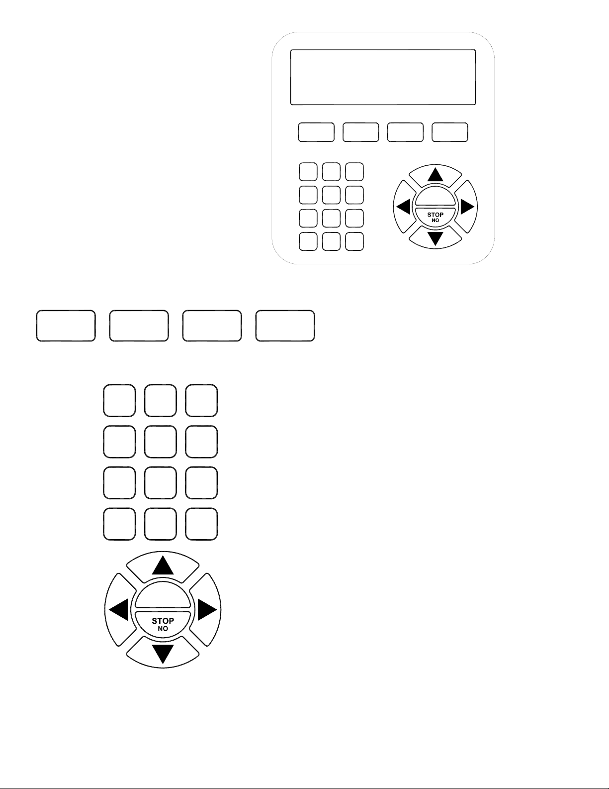
CONTROL PANEL
560-80450-00
AUTOMATIC RECYCLE VACUUM CHARGE
1
2
ABC
3
DEF
AUTOMATIC RECYCLE VACUUM CHARGE
1
4
GHI
PQRS7TUV8WXYZ
CLR
*
ABC2DEF
5
JKL
0
SPACE
MNO
U/M
3
6
9
#
YES
START
Pressing any one of these four buttons
causes the RHS980 to jump to the
respective procedure.
The alpha-numeric keypad is used to
enter data when prompted on the LCD
screen.
4
GHI
7
PQRS
CLR
*
5
JKL
8
TUV
0
SPACE
YES
START
6
MNO
9
WXYZ
#
U/M
Note: The # key also has U/M printed on
it. Pressing this key will toggle the units
of measure displayed on the LCD screen.
Note: Pressing the number 4 key
provides quick access to change
languages. Follow prompts to select
desired language.
Pressing any one of the arrow keys will
move the point of data entry on the LCD
screen in the respective direction.
Some screens provide options to select.
The arrow keys make it possible to select
the desired input.
The START and STOP buttons are used
to start or stop procedures as prompted
on the LCD screen.
7
Page 9

FIRST TIME USE
S
The first time a new RHS980 is powered up it will automatically perform a routine where the language is selected. The
language can be changed later if desired in the Setup Mode.
The RHS980 will arrive without any refrigerant. It will be necessary to put new refrigerant into the internal charge
cylinder before any other sequences can be run. The amount of refrigerant which to be transferred is factory set at 18
LB (8.16 KG). This amount can be adjusted if desired. Refer to SETUP section under DEFAULT VALUES to change
the factory setting. Connect the short yellow hose on the rear of the RHS980 to a new 30 lb. cylinder of refrigerant.
Open the cylinder valve, turn the cylinder up-side-down and place it on the platform. Secure with web belt.
Plug the power cord into an appropriate power source. Avoid using an extension cord. If necessary, use a good
condition, three wire grounded, #14 AWG or larger extension cord of the shortest possible length.
R H S 9 8 0
R T I - M A H L E C l e v i t e
X X X XXX
S E L E C T L A N G U A G E
►E N G L I S H E S P A Ñ O L
F R A N Ç A I S D E U T C H
▲ , ▼
W E I G H T = # # . # L B
A U T O M A T I C
S T A RT?
W E I G H T = # # . # L B
R E C Y C L E
S T A RT?
W E I G H T = # # . # L B
V A C U U M
S T A RT?
Press the Power Switch to turn on the RHS980.
The screen shown to the left will be displayed and a
buzzer will sound.
Press ▲ or ▼ key to scroll the displayed arrow to the
desired language. Press START key.
(Refer to Section CHANGING LANGUAGES for
additional information on loading new languages)
Note: Pressing the #4 key from the main menu will
access the language selection option.
The screen shown to the left will be displayed. Press
the ▼ key to scroll to the next screen.
Press ▼ key.
Press ▼ key.
W E I G H T = # # . # L B
C H A R G E
S T A RT?
W E I G H T = # # . # L B
F I L L C Y L I N D E R
S T A RT?
T A R T I N G R E F R I G E R A N T
I D E N T I F I E R
D O N O T C O N N E C T H O S E S
P L E A S E W A I T . . .
Press ▼ key.
Press START key. If the internal cylinder capacity
is equal to or greater than the target amount
shown in DEFAULT VALUES, the FILL CYLINDER
process will not be available from the main menu.
If the RHS980 has a refrigerant identifier installed, the
screen to the left and next 6 subsequent screens will
appear. The refrigerant identifier is an optional item
and can be installed in the field. Contact RTI for more
information.
8
Page 10

E X A M I N E I D S A M P L E
C O
G
O
S U
5 % A
H O S E / F I L T E R F O R O I L
S T A R T T O C O N T I N U E
S T O P T O E N D
N N E C T I D E N T I F I E R
S A M P L E H O S E T O L O W
S I D E
P R E S S Y E S W H E N D O N E
Inspect the identifier hose for traces of oil
contamination. If oil is present in the hose, remove the
contaminated hose section or replace the entire hose
assembly. See REFRIGERANT IDENTIFIER
MAINTENANCE section of manual. Press START key.
Connect refrigerant identifier hose found on the rear of
the RHS980 to the cylinder of new refrigerant. Unit
includes an adapter to convert the ½ inch Acme fitting
on the cylinder to low side coupler. Cylinder of new
refrigerant must be upright with valve at top of
tank. Press YES key.
A S A N A L Y S I S I S I N
P R O C E S S . . P L E A S E
W A I T
R E M
S A M P L E H O S E F R O M L O W
S I D E
P R E S S Y E S W H E N D O N E
I D R E
R 1 3 4 : # # . # % , A I R : # # . # %
H C : # # . # % P R E S S N O T O
R E J E C T , Y E S T O A C C E P T
>
E X C E S S O I L I N S A M P L E
H O S E / F I L T E R . R E M E D Y
B E F O R E U S E . C O N T I N U E ?
C O N N E C T H O S E T O
S O U R C E T A N K
O P E N V A L V E
S T A RT?
F I L L C Y L I N P R O C E S S
A M T F I L L E D # # . # L B
S T O P T O E N D
F I L L C Y L I N P R O C E S S
T I M E L E F T # # . # #
S T O P T O E N D
V E I D E N T I F I E R
L T S :
I R S U G G E S T S
Sample of new cylinder refrigerant is processed and
the hose and coupler must be removed. Press
START key.
This shows the results from the refrigerant sample
processed. Select NO key to reject these results or
YES key to accept the results. Pressing NO will return
to the initial screen.
If the results from the refrigerant identification show an
air percentage above 5%, this screen will appear.
Inspect the id filter, sample hose and coupler filter prior
to the next identification to ensure these devices are
free of oil contamination. See REFRIGERANT
IDENTIFIER MAINTENANCE section for more
information.
This is a reminder that the cylinder of new refrigerant
must be connected to the yellow hose on the rear of
the RHS980. Press START key.
Refrigerant will be transferred from the cylinder on the
rear platform into the internal charge cylinder of the
RHS980. Cylinder of new refrigerant must be
upside down with valve at bottom of tank.
The amount transferred will be displayed.
Note: Pressing the STOP key will start an internal
clearing process. This process must run to
completion to remove internal refrigerant.
9
Page 11

F I L L C Y L C O M P L E T E
A M T F I L L E D # # . # L B
S T O P T O E N D
The RHS980 is designed to recover, recycle and charge R134a. Take extreme precaution to ensure that other
refrigerants are not recovered into the RHS980.
A refrigerant identifier is recommended for evaluating refrigerant in the A/C system prior to servicing.
Recovering other refrigerants will contaminate the refrigerant in the RHS980 charge cylinder.
Sealants and leak stop chemicals in A/C systems may cause serious damage to the RHS980 if they are present in
the refrigerant recovered intended for recovery.
Detection devices are readily available to check for the presence of these chemicals and are highly recommended
to protect the RHS980.
REFRIGERANT BLENDS
LEAK SEALERS
The Fill Cylinder procedure is complete when desired
amount of refrigerant has been transferred. The Setup
procedure allows changing the value and is covered in
DEFAULT VALUES section in this manual.
Note: To fill to less than 18 LB (8.16 KG), close
valve on cylinder of new refrigerant and allow
procedure to complete. A minimum of 10 LB (4.53
KG) is suggested for truck service application. Do
not manually STOP process with out allowing the
RHS980 to clear the refrigerant from the
accumulator.
Call RTI for more information about solutions for detection of refrigerant blends and leak sealers.
10
Page 12
AUTOMATIC OPERATION
A
%
A
%
A
The AUTOMATIC function allows an operator to program an automatic recycle, vacuum, vacuum leak test and
charge sequence.
W E I G H T = # # . # L B
U T O M A T I C
S T A RT?
I D E N T I F I E R
D O N O T C O N N E C T H O S E S
P L E A S E W A I T . . .
H O S E / F I L T E R F O R O I L
S T A R T T O C O N T I N U E
S T O P T O E N D
S A M P L E H O S E T O L O W
S I D E
P R E S S Y E S W H E N D O N E
P R O C E S S . . P L E A S E
W A I T
S A M P L E H O S E F R O M L O W
S I D E
P R E S S Y E S W H E N D O N E
R 1 3 4 A: # # . #
H C: # #. #% P R E S S N O T O
R E J E C T, Y E S T O A C C E P T
>
E X C E S S O I L I N S A M P L E
H O S E / F I L T E R . R E M E D Y
B E F O R E U S E . C O N T I N U E ?
C H E C K O I L D R
L E V E L , A D J U S T O R I N G
T O T O P O F L E V E L
C O N T I N UE?
I R # #. #
I N
At the main menu screen, press the START key.
If the RHS980 has the optional refrigerant identifier
installed, the screen to the left and next 6 subsequent
screens will appear.
Inspect the identifier hose for traces of oil
contamination. If oil is present in the hose, remove the
contamination hose section or replace the entire hose
assembly. See REFRIGERANT IDENTIFIER
MAINTENANCE section of manual.
Connect refrigerant identifier hose found on the rear of
the RHS980 to the vehicle low side service port.
Press YES key.
Sample of vehicle A/C refrigerant is processed and the
hose and coupler must be removed. Press START
key.
This shows the results from the refrigerant sample
processed. Select NO key to reject these results or
YES key to accept the results. Pressing NO will return
to the initial screen.
If the results from the refrigerant identification show an
air percentage above 5%, this screen will appear.
Inspect the id filter, sample hose and coupler filter prior
to the next identification to ensure these devices are
free of oil contamination. See REFRIGERANT
IDENTIFIER MAINTENANCE section for more
information.
Adjust the O-Ring on the oil drain bottle to determine
how much oil has been removed from the system
during the service.
Press START key
NOTICE: If doing a Manual Oil Injection, you must only charge refrigerant to the
high side.
11
Page 13

P E R F O R M O I L
I N J E C T I O N?
S E L E C T Y E S O R N O
E N T E R V A C U U M
T I M E ## M I N
C O N T I N UE?
P E R F O R M L E A K T E S T
S E L E C T Y E S O R N O
U S E A C C A P A C I T Y
G U I D E T O D E T E R M I N E
C H A R G E A M O U N T ?
S E L E C T Y E S O R N O
V E R I F Y I N G D A T A B A S E
PLE A S E W A I T . . .
S E L E C T Y E A R
> # # # #
> # # # #
> # # # #
S E L E C T M A K E
> # # # #
> # # # #
> # # # #
Press YES key if you want to inject oil into the A/C
system after the Vacuum process has been
completed. After the vacuum process has been
completed the RHS980 will prompt you to inject the
desired amount of oil. Selecting oil injection will only
allow charging refrigerant to the high side or both
sides. Press NO key if no oil is to be injected into the
A/C system. If the RHS980 unit is enabled for the
HYBRID OIL FLUSH feature, the RHS980 will not
allow you to inject oil into the A/C system.
Enter the time desired to vacuum the A/C system.
Press START key.
Press YES key if a vacuum leak test is required.
Otherwise press NO key.
See SETUP SELECTABLE OPTIONS to enable or
disable AC CAPACITY GUIDE. To use the AC
capacity guide to determine the charge amount, press
YES key, otherwise press NO key. Pressing the YES
key will show next 7 subsequent screens.
Screen to the left will appear after the operator
selections are made and data is processed internally.
Select the year for the vehicle being serviced. Press
YES key on the highlighted value to continue. Use ▲
or ▼ key to scroll the displayed arrow to the desired
selection.
Select the make of the vehicle being serviced. Press
YES key on the highlighted value to continue. Use ▲
or ▼ key to scroll the displayed arrow to the desired
selection.
S E L E C T M O D E L
> # # # #
> # # # #
> # # # #
.
Select the model of the vehicle being serviced. Press
YES key on the highlighted value to continue. Use ▲
or ▼ key to scroll the displayed arrow to the desired
selection.
12
Page 14

A
A
A
A
A
S E L E C T E N G I N E
> # # # #
> # # # #
> # # # #
S E L E C T S Y S T E M
> # # # #
> # # # #
> # # # #
Y E A R, M O D E L, E N G I N E
S Y S T E M T Y P E X X, X X O Z
C O N D E N S E R C A P A C I T Y
X X O Z
E N T E R C H
# # . # L B
C O N T I N UE?
C U R R E N T O I L T Y P E
P A G / P O E
< > T O C H AN G E
C O N T I N UE?
S E L E C T T O C H
H I G H / L O W / B O T H
C O N T I N UE?
R G E A M O U N T
R G E
Select the engine configuration of the vehicle being
serviced, if more than 1 option is available. Press YES
key on the highlighted value to continue. Use ▲ or ▼
key to scroll the displayed arrow to the desired
selection.
If required, a screen to select the system for the
vehicle being serviced will be shown. Press YES key
on the highlighted value to continue. Use ▲ or ▼ key
to scroll the displayed arrow to the desired selection.
The data will be shown for the vehicle parameters
entered on this screen. Year, Make, Model, type,
system and refrigerant capacity in OZ is detailed.
Press ▼ key to display the next screen or YES key to
accept the charge amount.
Enter the amount of refrigerant to be charged into the
A/C system or the charge capacity will be
automatically entered if the AC database was used.
Press START key.
Press ► or ◄ key to change the type of oil which
exists on the A/C system being serviced. A HIGH
VOLTAGE OIL FLUSH will be started automatically if
the type is changed.
Press ► or ◄ key to select which side to charge to on
the A/C system. The word HIGH, LOW or BOTH will
display in bold letters. Note: If oil injection was
selected, only HIGH or BOTH will be enabled. Press
START key.
C O N N E C T H O S E S
O P E N V A L V E S
S T A RT?
R E C Y C L E I N P R O C E S S
M T R E C # # . # L B
S T O P T O E N D
R E C Y C L E I N P R O C E S S
M T R E C # # . # L B
T I M E L E F T # # M I N
S T O P T O E N D
V
C U U M I N P R O C E S S
T I M E L E F T # # M I N
L E V E L # # I N H G
S T O P T O E N D
Connect the red hose to the high side and the blue
hose to the low side of the A/C system. Open the
valves on both hoses. Press START key.
The RHS980 will now recover and recycle refrigerant.
The amount of refrigerant recovered will be displayed.
The next screen will be displayed when vehicle system
pressure is in a vacuum.
The RHS980 will now pause for the time entered
previously for Recycle Hold Time. The time left will be
displayed. This allows any liquid refrigerant in the A/C
system to vaporize. The RHS980 may cycle on and off
to recover refrigerant in this case.
The RHS980 will draw a deep vacuum on the A/C
system for the time entered in the default vacuum run
time in the set up menus. The time left and the
vacuum level in In-hg will be displayed.
13
Page 15

A
A
A
A
A
A
A
A
C H E C K V
T I M E L E F T # # M I N
S T A R T T O C O N T I N U E
S T O P T O E N D
L E
K T E S T F A I L E D
S T O P T O E N D
D D O I L N O W
C O N T I NUE?
P U R G E I N P R O C E S S
P L E A S E W A I T
S T O P T O E N D
C H
R G E I N P R O C E S S
M T C H G = # # . # L B
D O N O T D I S T U R B U N I T !
S T O P T O E N D
C U U M L E A K
The vacuum leak test will begin if selected earlier. The
time left will be displayed.
If leak test fails, press STOP key to end process.
Perform diagnostic on vehicle A/C system to find leak.
Correct vehicle system before resuming A/C service. If
vacuum test PASSED the RHS980 will progress to
operation below.
The RHS980 will pause so that the oil can be injected
if oil injection was previously selected. Check the oil
drain bottle to determine how much oil was removed
from the A/C system. Open valve on new oil bottle until
desired amount of oil has been drawn from the bottle.
Then close valve and press START key.
Use only new lubricant to replace the amount removed
during the recycling process. Used lubricant should be
discarded per applicable federal, state and local
requirements.
The RHS980 will purge air from the recovered
refrigerant if necessary. This process will be displayed.
The RHS980 will charge the amount of refrigerant set
previously into the A/C system. TO AVOID AN
INACCURATE CHARGE, DO NOT BUMP OR MOVE
THE RHS980 DURING THIS PROCESS.
M T R E C = # #. # # L B
M T C H G = # #. # # L B
C O N T I N UE?
S T
R T T O E V A C H O S E S
ST O P T O E N D
Press START key to proceed to the hose evacuation
procedure as outlined below.
Press START key to begin the hose evacuation
procedure.
14
Page 16

A
A
A
A
D I S C O N N E C T H S H O S E
N D S T A R T A / C M A X
C O N T I N UE?
E Q U
P L E A S E W A I T
D I S C O N N E C T L O W S I D E
H O S E , S H U T O F F E N G I N E
C O N T I N UE?
L I Z I N G H O S E S
C L E A R I N G H O S E S
M T R E C # # . # L B
T I M E L E F T # # M I N
S T O P T O E N D
E V A C H O S E S C O M P L E T E
I N S T A L L S E R V I C E C APS
D D O I L I F R E Q U I R E D
S T O P T O E N D
Close the high side coupler and disconnect from the
vehicle system coupler. Start the engine and place the
A/C system on max setting. Press START key.
While the engine and A/C system is running, liquid is
being removed from the services hoses. This ensures
only vapor remains in hoses.
Close the low side coupler and disconnect from the
vehicle system coupler. Turn off the vehicle engine.
Press START key.
A clearing procedure will run to remove refrigerant
from internal components.
Any vapor refrigerant remaining in the hoses will be
recovered into the RHS980.
The automatic cycle is complete when the hose
evacuation process is ended. Check level of oil
drained and add oil to the A/C system following
standard injection procedures. Reinstall service caps
onto vehicle A/C ports.
Press STOP key.
15
Page 17

A
A
A
A
PRINTING RESULTS
The RHS980 has an optional printer which allows the operator to print data collected during the AC system
service. Contact RTI for more information. If print to flash drive is enabled (SEE SELECTABLE OPTIONS) and
a flash drive is attached to the USB port, a duplicate report will be generated. File naming convention is:
YEAR, MONTH, DAY, SEQUENCE.TXT. Use any text editor software to view file contents.
W E I G H T = # # . # L B
U T O M A T I C
S T A RT?
W E I G H T = # # . # L B
P R I N T R E S U L T S
S T A RT?
E N T E R V I N N U M B E R
# # # # # # # # # # # # #
S T A R T T O C O N T I N U E
S T O P T O E N D
P R I N T I N G R E S U L T S
T O P R I N T E R
P L E A S E W A I T…
C L E
R R E S U L T S / D A T
C O L L E C T E D ?
S E L E C T Y E S O R N O
P R I N T
N O T H E R
R E P O R T ?
S E L E C T Y E S O R N O
Example of printout:
At the main menu screen, press the ▲ key 2 times.
See Printer Maintenance section if additional paper
is required.
Press START key.
Using the alpha-numeric keypad, enter the vehicle
identification number. Follow typical text messaging
methods to enter characters. After a brief delay during
entry, cursor position will move to the right. Press
START key when complete.
Press YES key if printing is complete or NO key if data
retention is required.
If NO key was entered above, an option to print
another report is offered. Press YES or NO key.
To remove print-out, tear at a slight angle as shown
below.
**********************
R T I T E C H N O L O G I E S
R H S 9 8 0
D A T E : # # - # # - # # # #
T I M E : # # : # #
S O F T W A R E R E V: 9 8 0 # # #
P R I N T O U T O F R E S U L T S
V I N : # # # # # # # # # # # # # # # # #
V E H I C L E D A T A
R E C Y C L E D : # # # #
V A C L E A K T E S T : # # # # # #
M I N V A C L E V E L : # # # # #
C H A R G E D : # # # #
* * * * * * * * * * * * * * * * * * * * * *
Units of measure on print-out are dependent on
selected units during normal operation.
Depending on the process performed, selected data
will be available for printing. Data is stored when the
processes are allowed to run until full completion.
16
Page 18

P R I N T I N G R E S U L T S
T O F L A S H D R I V E
P L E A S E W A I T…
If printing to a flash drive is enabled, then the screen
to the left will be shown and the data will be printed to
the flash drive.
HIGH VOLTAGE OIL FLUSH
An RHS980 configured from the factory to perform service on high voltage systems is designated RHS980H.
The RHS980H has the ability to perform an internal oil flushing process to eliminate cross contaminations
between PAG oil used in a conventional R-134a system and POE oil used in HIGH VOLTAGE HYBRID
systems. The POE oil acts as a lubricant, but more importantly the POE oil is required to keep the HIGH
VOLTAGE system isolated from the chassis. If the HYBRID’s system becomes conductive, the service
technician can be at risk of electrical shock. During the HIGH VOLTAGE OIL FLUSH process the residual
PAG oil from previous services will be flushed from the HIGH - Low side couplers and hoses along with the
corresponding internal passages of the RHS980H unit.
IMPORTANT – THE HIGH VOLTAGE OIL FLUSH PROCESS MUST BE PERFORMED
BEFORE A SERVICE ON A HYBRID VEHICLE IS CONDUCTED!
IT IS THE SERVICE TECHNICIANS RESPONSIBILITY TO UNDERSTAND THE RISKS
INVOLVED IN SERVICING A HIGH VOLTAGE HYBRID A/C SYSTEM, AS WELL AS
DETERMING THE PROPER OIL REQUIRED FOR THE HYBRIDS A/C SYSTEM TO ENSURE
ITS ELECTRICAL ISOLATION FROM THE VEHICLES CHASSIS IS MAINTAINED.
Units that are configured for the High Voltage Oil Flush, there will be a screen illustrated below that will start
the High Voltage Oil Flush process, as well the RHS980H will NOT have the oil injection feature. The oil
injection bottle and connections will NOT be present next to the oil drain bottle. The High Voltage Oil Flush
configured unit will also be shipped with a HIGH -LOW side adapter so that the hoses can be connected to
flush residual PAG oil from previous services. To access to the HIGH VOLTAGE OIL FLUSH FEATURE, follow
the procedure below.
W E I G H T = # # . # L B
A U T O M A T I C
S T A RT?
W E I G H T = # # . # L B
R E C Y C L E
S T A RT?
W E I G H T = # # . # L B
V A C U U M
S T A RT?
W E I G H T = # # . # L B
C H A R G E
S T A RT?
The screen shown to the left will be displayed. Press
the ▼ key to scroll to the next screen.
Press ▼ key.
Press ▼ key.
Press ▼ key.
17
Page 19

W E I G H T = # # . # L B
F I L L C Y L I N D E R
S T A RT?
W E I G H T = # # . # L B
T E C H A L E R T D E M O
S T A RT?
W E I G H T = # # . # L B
H I G H V O L T A G E O I L
F L U S H S T A RT?
C O N N E C T E X T F L U S H
D A P T E R T O L O W A N D
A
I G H S I D E C O U P L E R S
H
C O N T I N UE?
A R G E I N P R O C E S S
CH
A M T C H G = # #. # # L B
D O N O T D I S T U R B U N I T !
S T O P T O E N D
E C Y C L E I N P R O C E S S
R
A M T R E C # # . # # LB
T I M E L E F T # # : # #
S T O P T O E N D
H I G H V O L T A G E O I L
F L US H C O M P L E T E
S T O P T O E N D
Press ▼ key.
Press ▼ key.
Press START key.
Connect the HIGH and LOW side couplers with the
supplied HIGH VOLTAGE OIL FLUSH adapter as shown
below, open HIGH and LOW side couplers. Press the
START key.
The RHS980 will perform the HIGH VOLTAGE OIL
FLUSH process at this time.
Press STOP key to end the process, disconnect the
HIGH and LOW service couplers from the HIGH
VOLTAGE OIL FLUSH adapter
18
Page 20

SETUP
A
A
A
A
A
The setup procedure provides a means of setting options for various operation functions of the RHS980.
W E I G H T = # # . # L B
U T O M A T I C
S T A RT?
W E I G H T = # # . # L B
S E T U P
S T A RT?
SELECTABLE OPTIONS
S E L E C T
C O N T I N UE?
S E L E C T L
► E N G L I S H E S P A Ñ O L
F R A N Ç A I S
▲ , ▼
Default is ENGLISH.
B U Z Z E R E N
► Y E S
N O ▲
▼
Default is YES.
R E F R I G I D I N S T
Y E S
► N O ▲
▼
Default is NO.
B L E O P T I O N S
N G U A G E
B L E D ?
L L E D ?
The initial screen displayed after turning on power will
be as shown to the left.
Press the ▼ key to scroll through screens until the
setup screen shown to the left is displayed. Press the
START key.
The first screen will be for SELECTABLE OPTIONS.
Press the ▼ key to scroll through other setup screens:
DEFAULT VALUES, MAINTENANCE OPTIONS and
TOTAL CAPACITIES. These four setup procedures
are described below. Press START key.
The first option is to select the language which is used
on LCD display screens.
Press ▲ or ▼ key to scroll the displayed arrow to the
desired language. Press START key.
Note: Pressing the #4 key from the main menu will
access the language selection option.
This enables or disables the buzzer on the RHS980.
Press the ▲ or ▼ key to scroll to YES or NO. Press
START key.
This enables the RHS980 to interact with the RTI
Refrigerant Identifier. If this optional item was not
installed at the factory, visit the RTI web-site for more
information. Press the ▲ or ▼ key to scroll to YES or
NO. Press START key.
19
Page 21

A
A
A
A
A
A
A
A
C C A P D B I N S T A L L E D ?
► N O
I N T E R N A L ▲
E X T E R N A L ▼
Default is NO.
P R I N T E R I N S T
Y E S
► N O ▲
▼
Default is NO.
P R I N T T O F L
► Y E S
N O ▲
▼
Default is YES.
L L E D ?
S H D R I V E
This enables the RHS980 to interact with the RTI
Refrigerant Capacity Database. If NO is selected, the
operator will not be prompted prior to charge to access
the AC Capacity Database for the vehicle charge
amount. Selecting external and having flash drive with
the All Makes Database attached to the unit USB port,
all other manufacturers charge capacities will be
available. Press the ▲ or ▼ key to scroll to choices.
Press START key.
Contact RTI for more information.
This enables or disables the on board printer on the
RHS980. Press the ▲ or ▼ key to scroll to YES or
NO. Press START key.
Use to enable or disable printing service results or
setup parameters as files on the attached flash drive.
Press the ▲ or ▼ key to scroll to YES or NO. Press
START key.
L O W V O L T
E N A B L E D ?
Y E S ▲
► N O ▼
Default is NO.
MI CR ON V
SENSOR EN A B L E D ?
Y E S ▲
► N O ▼
Default is NO.
P
S S W O R D P R O T E C T I O N
EN A B L E D?
► Y E S ▲
N O ▼
Default is YES.
E N T E R P
# # # #
S T A R T T O C O N T I N U E ▲
S T O P T O E N D ▼
S T
EN A B L E D?
► N O ▼
Default is No.
R T U P P A S S W O R D
Y E S ▲
G E D E T E C T
CUUM
S S W O R D
This feature is not applicable to the base RHS980 and
RHS980 with High voltage oil flush. Enabling this
feature will compromise the functionality of the unit.
Press START key.
This feature is not applicable to the base RHS980 and
RHS980 with High voltage oil flush. Enabling this
feature will compromise the functionality of the unit.
Press START key.
This feature can be enabled on base RHS980 and
RHS980 with High Voltage Oil Flush. IMPORTANT
The manager password will also be required to make
any changes in the Selectable Options and the
Default Values sections if enabled. See Maintenance
Options in regards to default password and changing
passwords. Press START key. If NO is selected the
following screen will be shown.
Default Service Managers password is 5237, enter this
password to continue. Proceed to Maintenance
Section to see how to change default password to one
of the 20 optional passwords. Press START key.
An operator password will be required to proceed with
any operation after powering the unit if this feature has
been enabled.
20
Page 22

A
A
A
A
A
A
A
A
V I N E N T R Y E N
► Y E S ▲
N O ▼
Default is YES.
O P E R
Y E S ▲
► N O ▼
Default is NO.
C T E S T M O D E
EN A B L E D ?
Y E S ▲
► N O ▼
Default is NO.
V
T E S T E N A B L E D ?
Y E S ▲
► N O ▼
Default is NO.
R E F R I G E R
F L U S H E N A B L E D ?
Y E S ▲
► N O ▼
Default is NO.
T E C H
E N A B L E D ?
► Y E S ▲
N O ▼
Default is YES.
H I G H P R E S S U R E L E
D E T E C T E NA B L E D ?
Y E S ▲
► N O ▼
Default is NO.
U T O M A T I C W E I G H I N G
O I L I N J E C T I O N E N A B L E D
Y E S ▲
► N O ▼
Default is NO.
T O R I D E N T R Y
C U U M P U M P O I L L I F E
N T L I Q U I D
L E R T D E M O M O D E
B L E D ?
K
This feature allows the vehicles VIN to be entered that
is being serviced. Press START key.
This feature is not applicable to the base RHS980 and
RHS980 with High voltage oil flush. Enabling this
feature will compromise the functionality of the unit.
Press START key.
This feature is not applicable to the base RHS980 and
RHS980 with High voltage oil flush. Enabling this
feature will compromise the functionality of the unit.
Press START key.
This feature is not applicable to the base RHS980 and
RHS980 with High voltage oil flush. Enabling this
feature will compromise the functionality of the unit.
Press START key.
This feature is not applicable to the base RHS980 and
RHS980 with High voltage oil flush. Enabling this
feature will compromise the functionality of the unit.
Press START key.
Enabling this feature will allow the user to demonstrate
the TechALERT capabilities without actually
performing a service. Press START key.
This feature is not applicable to the base RHS980 and
RHS980 with High voltage oil flush. Enabling this
feature will compromise the functionality of the unit.
Press START key.
This feature is not applicable to the base RHS980 and
RHS980 with High voltage oil flush. Enabling this
feature will compromise the functionality of the unit.
Press START key.
21
Page 23

A
A
A
A
A
A
A
U T O M A T I C W E I G H I N G
O I L D R A I N E N A BLED?
Y E S ▲
► N O ▼
Default is NO.
U T O M A T I C W E I G H I N G
U V D Y E E N A BLED?
Y E S ▲
► N O ▼
Default is NO.
H I G H V O L T
F L U S H E N A B L E D ?
Y E S ▲
► N O ▼
Default is YES if purchased with this feature, Default is
NO, if not purchased with this feature.
F I L L C Y L I N D E R
E N A B L E D?
► Y E S ▲
N O ▼
Default is YES.
M
N U A L O I L I N J E C T I O N
E N A B L E D?
► Y E S ▲
N O ▼
Default is YES.
DEFAULT VALUES
D E F
C O N T I N UE?
F I L L C Y L I N D E R T
M O U N T # # . # # L B
B E T W E E N 6. 6 & 2 4. 2 L B
C O N T I N UE?
U L T V A L U E S
G E O I L
R G E T
This feature is not applicable to the base RHS980 and
RHS980 with High voltage oil flush. Enabling this
feature will compromise the functionality of the unit.
Press START key.
This feature is not applicable to the base RHS980 and
RHS980 with High voltage oil flush. Enabling this
feature will compromise the functionality of the unit.
Press START key.
This feature is not applicable to the base RHS980 but
is enabled on RHS980 units with high voltage oil flush
capability.
WARNING DO NOT ENABLE THIS FEATURE IF
YOUR UNIT IS NOT CONFIGURED FOR HIGH
VOLTAGE OIL FLUSH. IF YOUR UNIT HAS AN OIL
INJECTION BOTTLE AND CONNECTION POINT TO
INJECT OIL INTO THE A/C SYSTEM
DO NOT
ENABLE THIS FEATURE. Press START key.
This feature allows the operator to fill the internal
cylinder of the RHS980 from an external virgin
refrigerant tank to the preset amount, see Default
Values. Press START key.
This feature allows the operator to inject oil into the
A/C system on NON- HYBRID vehicles, after the
vacuum process has been performed. This feature is
NOT enabled from the RTI factory and SHOULD NOT
be enabled in the field on units that are configured for
HIGH VOLTAGE OIL FLUSH for HYBRID vehicles.
Press START key.
If doing a Manual Oil Injection, you must
only charge refrigerant to the high or both
Press START key.
The Fill Cylinder procedure will automatically transfer
refrigerant from a new cylinder of refrigerant to the
internal RHS980 charge cylinder. The value set here
will be the amount of refrigerant which will have been
transferred when the procedure stops automatically.
Enter an amount between 3 and 11 KG (6.6 and 24.2
LB). The value will be displayed as it is entered. Press
START key. (Default is 8.00 KG (17.6 LB))
sides.
22
Page 24

A
A
A
A
A
A
A
A
A
A
A
A
I N I T I
# # # # # M I C R O N
B E T W E E N 3 K & 9 K
C O N T I N UE?
F I N
# # # # # M I C R O N
B E T W E E N 1 K & 9 K
C O N T I N UE?
V
C U U M R U N T I M E
# # M I N
B E T W E E N 1 & 9 9 M I N
C O N T I N UE?
H O S E S O V E R C H
M O U N T # . # # K G
B E T W E E N 0 & 2. 2 L B
C O N T I N UE?
D E F
V O L T A G E # # # V A C
B E T W E E N 9 0 & 1 2 0 V AC
C O N T I N UE?
E L E V
L E V E L # # # # # F T
B E T W E E N 0 & 3 0 K F E E T
C O N T I N UE?
L V A C U U M H O L D
L V A C U U M L E V E L
R G E
U L T M I N I M U M L I N E
T I O N F R O M S E
This feature is not applicable to the base RHS980 and
RHS980 with High voltage oil flush. Enabling this
feature will compromise the functionality of the unit.
Press START key
This feature is not applicable to the base RHS980 and
RHS980 with High voltage oil flush. Enabling this
feature will compromise the functionality of the unit.
Press START key
This screen prompts for the length of time the vacuum
pump will run during each cycle. There is one initial
cycle to pull the system for an initial vacuum leak test,
then a second cycle to obtain the final micron level.
Enter a number of minutes between 1 and 99. The
value will be displayed as it is entered. Press START
key. (Default is 10 MIN)
A small overcharge of refrigerant is necessary to
compensate for refrigerant which will remain in the
hose after a charge procedure. Enter the number of
KG between 0 and 0.99 (0 and 2.2 LB). The value will
be displayed as it is entered. Press START key.
Change to value must be verified by service
manager by entering a password. (Default is 0.02
KG (0.04 LB))
This feature is not applicable to the base RHS980 and
RHS980 with High voltage oil flush. Enabling this
feature will compromise the Functionality of the unit.
Press START key.
Elevation from sea level used to adjust pressure
transducer calibration. Enter a number in feet from 0
to 30,000 feet. The elevation can be obtained by
calling your local airport. Press START key. (Default is
400 FT)
O I L L I F E V
L E V E L # # # M I C R O N
B E T W E E N 2 5 & 2 0 0
C O N T I N UE?
O I L D R
# # # M L
B E T W E E N 5 0 & 2 0 0 M L
C O N T I N UE?
M I N I M U M V
L E V E L # # I N H G
B E T W E E N 1 5 & 2 5
C O N T I N UE?
H I G H V O L T
C H G A M T1 . 6 L B
B E T W E E N 0. 1 & 2. 0 L B
C O N T I N UE?
I N M A X L E V E L
C U U M R I S E
C U U M L E AK
G E F L U S H
This feature is not applicable to the base RHS980 and
RHS980 with High voltage oil flush. Enabling this
feature will compromise the functionality of the unit.
Press START key.
This feature is not applicable to the base RHS980 and
RHS980 with High voltage oil flush. Enabling this
feature will compromise the functionality of the unit.
Press START key.
During vacuum leak test, this value is used to
determine a pass or fail.
The Default value is 1.6 lbs for the HIGH VOLTAGE
OIL FLUSH. WARNING, DO NOT REDUCE THIS
SETTING TO LESS THAN 1.6 LBS AS THE
FLUSHING PROCESS WILL NOT BE COMPLETED
PROPERLY AND RESIDUAL OIL MAY BE LEFT IN
LINES. Press START key.
23
Page 25

D E F A U L T VA C U U M L E AK
A
A
A
A
A
A
A
A
T I M E 1 0 M I N
B E T W E E N 1 A N D 9 9 M I N
C O N T I N UE?
MAINTENANCE OPTIONS
P E R F O R M C
C H E C K ?
S E L E C T Y E S O R N O
RTI recommends checking calibration every 3 months
T T A C H W E I G H T T O
B O T T O M O F M A C H I N E
C O N T I N UE?
C
L I B R A T I O N A P P R O V E D
R E M O V E W E I G H T
C O N T I N UE?
Or the next screen may be displayed…
C
L I B R A T I O N R E J E C T E D
R E C A L I B R A T E U N I T O R
C A L L F O R S E R V I C E
C O N T I N UE?
P E R F O R M I N T E R N
C Y L I N D E R L O A D C E L L
S I T E C A L I B R A T I O N ?
S E L E C T Y E S O R N O
T T A C H W E I G H T T O
B O T T O M O F M A C H I N E
C O N T I N UE?
C
L I B R A T I O N A P P R O V E D
R E M O V E W E I G H T
C O N T I N UE?
Or the next screen may be displayed…
C
L I B R A T I O N R E J E C T E D
R E C A L I B R A T E U N I T O R
C A L L F O R S E R V I C E
C O N T I N UE?
L I B R A T I O N
L
During vacuum process, a vacuum leak process will
be provided to check system for potential leaks.
Default value is 10 minutes. Press START key.
The calibration of the weight scale in the RHS980 can
be easily checked using this procedure. A steel ball of
a precise weight is provided with the RHS980 for
performing this calibration check. Unit must show
positive weight on scale prior to selecting this
procedure. Press YES key. Access to unit calibration
must be verified by service manager by entering a
password.
The screen prompts to attach the steel ball to the
bottom of the machine. There is a small post which
protrudes through the bottom plate of the RHS980
(see Parts Identification at rear of this Operation
Manual). This post is magnetic. Attach the calibration
check weight (steel ball) to this post. Press START
key.
This screen will display if the weight scale is in
calibration. If calibration check failed, the RHS980
must be fully calibrated. See below.
This screen will display if the weight scale is not in
calibration. To perform a full load cell calibration
procedure, press START key.
Press YES key if a calibration is required. Otherwise,
press NO key. Special RTI 4 KG (8.8 LB) weight IS
required to calibrate the scale, do not use steel
ball supplied with the machine! Unit must show
positive weight on scale prior to selecting this
procedure. Load cell calibration should be performed
by qualified technicians only and should be performed
at least once per year. Call RTI technical support for
more information. 1-800-468-2321 X 1
The screen prompts to attach the 4 KG (8.8 LB) weight
to the bottom of the machine. There is a small post
which protrudes through the bottom plate of the
RHS980 (see Parts Identification at end of this
Operation Manual). This post is magnetic. Attach the 4
KG calibration weight to this post. Press START key.
The weight scale is now calibrated. Remove the
calibration weight. Press START key.
This screen will display if the weight applied does not
meet the minimum required. For example; attempting
to use the calibration ball instead of the approved 4
KG (8.8 LB) calibration weight. Perform a shop load
cell calibration procedure or call RTI technical support
for more information. 1-800-468-2321 X 1
24
Page 26

P E R F O R M I N T E R N A L
A
A
A
A
A
A
A
C Y L I N D E R L O A D C E L L
S H O P C A L I B R A T I O N ?
S E L E C T Y E S O R N O
Press YES key if a calibration is required. Otherwise,
press NO key. Special RTI 10 KG (22 LB) weights
are required to calibrate the scale, do not use steel
ball supplied with the machine! Load cell calibration
should be performed by qualified technicians only and
should be performed at least once per year. Call RTI
technical support for more information. 1-800-4682321 X 1
C O N N E C T C Y L I N D E R T O
L O W S I D E H O S E A N D
O P E N V A L V E
C O N T I N UE?
C H
R G E I N P R O C E S S
M T C H G = # # . # # L B
C O N T I N UE?
C
L I B R A T I O N M I N
W E I G H T O N
C O N T I N UE?
C
L I B R A T I O N M A X
W E I G H T O N
C O N T I N UE?
C
L I B R A T I O N C O M P L E T E
R E M O V E W E I G H T
M O U N T = # # # # # X X
C O N T I N UE?
Or the next screen may be displayed…
C
L I B R A T I O N F A U L T
I N S U F F I C I E N T W E I G H T
C O N T I N UE?
If YES key was pressed, this screen will display.
Connect the blue low side hose of the RHS980 to the
vapor port of a refillable DOT cylinder. Open the valve
on the cylinder. Press START key. Refrigerant will be
transferred from the RHS980 internal cylinder into the
externally connected DOT cylinder.
This screen will display a decreasing amount as
refrigerant is transferred to the DOT cylinder. Press
START key when the amount does not decrease any
more.
This screen indicates the weight scale is reading a
minimum weight since the charge cylinder is empty.
Press START key.
This screen prompts for maximum weight. Place the
calibration weights on top of the RHS980 charge
cylinder. The weight scale will now read a maximum
weight. Press START key.
The weight scale is now calibrated. Remove the
calibration weights. Press START key.
This screen will appear if the weight used does not
meet the required minimum. For example; attempting
to use the 4 KG (8.8 LB) weight or calibration ball
instead of the approved 10 KG (22 LB) calibration
weight. Call RTI technical support for more
information. 1-800-468-2321 X 1
25
Page 27

A
A
A
A
A
S E T D
# # - # # - # # # #
# # : # # : # #
S E L E C T Y E S O R N O
S E T T H E D
Y Y Y Y - M M - D D ▲
M M - D D - Y Y Y Y ▼
C O N T I N UE?
S E T T H E Y E
# # # # ▲
▼
C O N T I N UE?
S E T T H E M O N T H
# # ▲
▼
C O N T I N UE?
S E T T H E D
# # ▲
▼
C O N T I N UE?
S E T T H E H O U R
# # : # # ▲
▼
C O N T I N UE?
S E T T H E M I N U T E S
# # : # # ▲
▼
C O N T I N UE?
C C E P T T H E S E V A L U E S ?
# # - # # - # # # #
# # : # #
S E L E C T Y E S O R N O
T E A N D T I M E ?
T E F O R M AT
R
Y
Press YES key if adjustment to the date and time is
required. Otherwise, press NO key.
The format for the date is selected by pressing START
key. Change highlighted format with the ▲ or ▼ key.
Using ▲ or ▼ key, increase or decrease the year.
Press START key to continue.
Using ▲ or ▼ key, increase or decrease the month.
Press START key to continue.
Using ▲ or ▼ key, increase or decrease the day.
Press START key to continue.
Using ▲ or ▼ key, increase or decrease the hour.
Press START key to continue.
Using ▲ or ▼ key, increase or decrease the minutes.
Press START key to continue.
Press YES key to accept the date and time changes,
press NO key to return without changes.
Unit contains a battery to save time and date.
Battery life is dependent on many conditions. See
Parts Identification for replacement battery P/N.
26
Page 28

A
A
A
A
A
A
U S E ▲ ▼ T O C H
S E L E C T E D O U T P U T
S T A R T T O G G L E S O N & O F F
S T O P T O E N D
U S E ▲ ▼ T O C H
S E L E C T E D I N P U T
S T O P T O E N D
# # # # # # # # # # #
P E R F O R M C O M B O F I L T E R
R E P L A C E M E N T ?
S E L E C T Y E S O R N O
C H E C K I N G
P R E S S U R E S
P L E A S E W A I T
R E M O V E
C O M B O F I L T E R
C O N T I N UE?
E N T E R F I L T E R S E R I
N U M B E R
# # # # # #
C O N T I N UE?
P E R F O R M V
O I L R E P L A C E M E N T
S E L E C T Y E S O R N O
R E F E R T O M
C O M P L E T E I N S T R U C T I O N
F O R V A C O I L C H A N G E
C O N T I N UE?
N D R E P L A C E
C U U M P U M P
N U A L F O R
N G E
N G E
L
Inputs and outputs of devices in the RHS980 can be
checked for diagnostic purposes. Press YES key.
Press ▲ or ▼ key to select various outputs. The
output identification number will display on the screen.
For a selected output, press the START key to toggle
it on and off. Press STOP key to advance to next
screen.
Press ▲ or ▼ key to select various inputs. The input
identification number will display on the screen. For a
selected input, press the START key to toggle it on
and off and display units. Press STOP key to advance
to next screen.
The RHS980 combo filter must be replaced after every
150 LB (68 KG) of refrigerant has been recovered from
A/C systems. A reminder message will appear after
the filter capacity reaches 125 LB (57 KG) and the unit
is powered ON. Press YES to start the procedure to
change the combo filter. This filter can be accessed by
removing the literature pocket on the left side of the
RHS980. Press YES key.
Internal pressure of the combo filter will be checked. If
pressure is detected a buzzer will sound and the
display will indicate the need to go to recycle mode to
eliminate the pressure.
This screen will display if pressure was not detected.
Replace the combo filter. Note the serial number on
the new combo filter label as it may not be visible
when installed. Press START key.
Enter the new six digit combo filter serial number.
Press START key.
The RHS980 records the hours of vacuum pump use
and prompts after every 10 hours that the oil should be
changed. Earlier replacement of oil may be required if
oil appears cloudy or vacuum performance is
unsatisfactory. Press YES key to replace the vacuum
pump oil.
Refer to Vacuum Pump Maintenance Section in this
manual for complete instructions for the vacuum pump
oil change procedure. Press START key when oil has
been changed. RTI recommends changing of both inline hose screen filters at this interval also. See
PARTS IDENTIFICATION section for details.
27
Page 29

A
A
A
A
A
A
A
A
C H
N G E O P E R A T O R
P A S S W O R D S ?
S E L E C T Y E S O R N O
E N T E R P
# # # #
S T A R T T O C O N T I N U E
S T O P T O E N D
P
S S W O R D A C C E P T E D
S T A R T T O C O N T I N U E
S T O P T O E N D
Or the next screen may be displayed….
P
S S W O R D R E J E C T E D
S T A R T T O C O N T I N U E
S T O P T O E N D
N U M K E Y S T O C H
U S E ▲ ▼ T O S C R O L L
S T A R T T O C O N T I N U E
S TOP T O E N D
7 5 8 4 4 4 3 5 9 1 1 5 ▲
1 0 2 8 0 9 9 6 1 5 3 4
8 1 9 0 1 3 7 6 1 0 8 0
2 8 3 9 5 9 0 6 6 9 6 9 ▼
2 1 9 2 3 2 6 0 6 2 2 9 ▲
2 2 7 0 8 9 8 3 7 1 8 8
2 9 3 9 1 8 7 8
▼
S S W O R D
N G E
One of the 20 optional passwords stored in the
RHS980 can be used for password protection and can
be changed by performing the operation to the left.
Press START key to continue.
If YES was selected you will see the next 7
subsequent screens. The RHS 980 will prompt to enter
the service managers password, default is 5237, this
password was previously used to enable the password
protection feature. Press START key to continue.
This screen will be shown after the Default Password
has been accepted. Press START key to continue.
If the Default Service managers password is rejected,
this screen is shown. Check the password and press
START key.
The numeric keys are used to change the password
which is selected. Use the ▲,▼,► and ◄ key to
change the highlighted password selection. Press
START key.
20 default passwords are shown. Passwords can be
assigned to each service technician individually. It is a
recommended practice to record these passwords in a
secure location. After changes are complete, press
START key to continue and accept changes.
S S W O R D S A C C E P T E D
P
C O N T I N UE?
C H
N G E S E R V I C E
M A N A G E R S P A S S W O R D
S E L E C T Y E S O R N O
E N T E R P
# # # #
S T A R T T O C O N T I N U E
S T O P T O E N D
S S W O R D
Press START key.
If YES was selected above to change operators
password, the RHS980 will give the option to change
the Service Managers password, if this option is
desired, press YES key.
Enter the default Service managers password. Press
START key.
28
Page 30

A
A
A
A
P
S S W O R D S A C C E P T E D
C O N T I N UE?
E N T E R N E W S E R V I C E
M A N A G E R S P A S S W O R D
# # # #
C O N T I N UE?
P
S S W O R D U P D A T E D
C O N T I N UE?
P R I N T P
R A M E T E R
S E T T I N G S ?
S E L E C T Y E S O R N O
Example of printout:
**********************
R T I T E C H N O L O G I E S
R H S9 8 0
D A T E : # # - # # - # # # #
T I M E : # # : # #
P R I N T O U T P A R A M E T E R S E T
I T E M D E F S E T
L A N G U A G E E N G X X X
B U Z Z E R N O X X X
R E F I D N O X X X
A C D B I N T X X X
P R I N T E R Y E S X X X
P R T F D N O N O
F I L L T A R G 8 . 0 0 X X X X X
I N T V A C 5 0 0 0 X X X X X
F I N V A C 2 0 0 0 X X X X X
V A C R U N T 1 0 X X
H O S E O V R 0 . 0 2 X . X X
M I N V O L T 9 0 X X X
E L E V S E A 4 0 0 X X X X X
O I L R I S E 5 0 X X X
* * * * * * * * * * * * * * * * * * * * * *
TOTAL CAPACITIES
T O T
L C A P A C I T I E S
C O N T I N UE?
This screen will be shown after the Default Password
has been accepted. Press START key to continue.
Enter the Service Managers new 4 digit password and
press YES to continue. Important once the Service
Managers default password has been changed, the
password must be remembered to make any further
changes.
This screen will be shown after the new Service
Managers password has been accepted. Press
START key to continue.
The RHS980 has the capability to print all of the user
selectable parameters to the printer or to a file. Press
YES key to access this feature.
If printing to a flash drive is enabled in the
SELECTABLE OPTIONS section, a file will be created
containing the parameter listing. File naming
convention is as follows: paramtr.txt. New data printed
will be appended to the end of the file. Use any text
editor software to view file contents.
The RHS980 records data which can be used for shop
management of the equipment and refrigerant usage.
Press START key.
C O M B O F I L T E R L I F E
R E M A I N I N G # # # L B S
C O N T I N UE?
The RHS980 combo filter must be replaced after every
150 LB (68 KG) of refrigerant has been recovered from
A/C systems. An alert will display when the filter life is
at 100 LB (45.35 KG). The RHS980 will shut down
when the filter life is at 150 LB (68 KG). A new filter
must be installed and a serial number entered to restart the RHS980. Press START key to go to next
screen.
29
Page 31

A
A
A
A
T O T
R E C Y C L E D # # # # # L B
C O N T I N UE?
T O T
C H A R G E D # # # # # L B
C O N T I N UE?
V
R E M A I N I N G # # H O U R S
C O N T I N UE?
REMINDERS
R E M I N D E R : C
S E R V I C E T O C H E C K
S C A L E C A L I B R A T I O N
C O N T I N UE?
R E M I N D E R : P E R F O R M
CA L I B R A T I O N C H E C K ?
C O N T I N UE?
L R E F R I G E R A N T
L R E F R I G E R A N T
C U U M P U M P O I L L I F E
L L
The RHS980 records the total refrigerant which has
been recycled. That total is displayed on this screen.
Press START key to go to next screen.
The RHS980 records the total refrigerant which has
been charged. That total is displayed on this screen.
Press START key to go to next screen.
The RHS980 records the hours the vacuum pump
runs. A reminder screen displays when that total
equals 10 hours. The vacuum pump oil should be
changed at that time. This screen displays the hours
remaining until the reminder screen will display. Press
START key to continue.
After 1 year, a reminder to schedule service to check
the internal scale calibration will be shown. Call RTI to
assist with scheduling maintenance with a service
center. Press START key to continue.
After 3 combo filter changes, a reminder to perform a
scale calibration check will be prompted. Follow
MAINTENANCE OPTIONS section of the manual for
more details. Press START key to continue.
TechALERT DEMO MODE
The RHS980 has been configured with a TechALERT demonstration mode. This feature allows the user to
witness the signals that will be sent from TechALERT base as well as what signals will be received with the
TechALERT remote. To reach the TechALERT demo mode feature, follow the procedure below.
W E I G H T = # # . # L B
A U T O M A T I C
S T A RT?
W E I G H T = # # . # L B
R E C Y C L E
S T A RT?
W E I G H T = # # . # L B
V A C U U M
S T A RT?
The screen shown to the left will be displayed. Press
the ▼ key to scroll to the next screen.
Press ▼ key.
Press ▼ key.
30
Page 32

W E I G H T = # # . # L B
C H A R G E
S T A RT?
W E I G H T = # # . # L B
F I L L C Y L I N D E R
S T A RT?
W E I G H T = # # . # L B
T E C H A L E R T D E M O
S T A RT?
S E L E C T D E M O M O D E
U T O M A T I C
A
M
U A L
AN
C O N T I N UE?
Press ▼ key.
Press ▼ key.
Press START key.
Select either the AUTOMATIC mode or MANUAL
mode, if AUTOMATIC mode is selected follow the
subsequent 5 screens. If MANUAL was selected see
below. Use the ▲ or ▼ key to change the selection.
Press START key.
S I G N A L W I L L C HA
U T O M A T I C A L L Y A F T E R
A
0 S E C O N D S
3
C O N T I N UE?
NGE
S E ND I N G R U N N I N G
L E D G R E E N, B U Z Z O F F
V I B O F F, T I M E L E FT # #
S T O P T O E N D
S E ND I N G F A U L T
L E D R E D, B U Z Z O F F
V I B O N, T I M E L E FT # #
S T O P T O E N D
S E ND I N G C O M P L E T E
L E D G R N/ Y E L, B U Z Z O N
V I B O N, T I M E L E FT # #
S T O P T O E N D
S E ND I N G C L EA R S I G NAL
L E D O F F, B U Z Z O F F
V I B O F
S T O P T O E N D
T I M E L E FT # #
F,
S E L E C T D E M O M O D E
U T O M A T I C
A
M
U A L
AN
C O N T I N UE?
P R E S S # 1= R U N , # 2 =
F A U L T , # 3 = C O M P L E T E ,
# 0 = C L E A R
S T O P T O E N D
The signal will be sent for 30 seconds before switching
to the next signal.
RUNNING signal being sent.
FAULT signal being sent.
COMPLETE signal being sent.
Press the STOP key to end TechALERT automatic
demo mode.
If MANUAL mode is selected follow the subsequent
screens. Use the ▲ or ▼ key to change the selection.
Press START key.
When in TechALERT manual demo mode, push the
corresponding key on the keypad to witness the
desired signal.
Press the STOP key to end the TechALERT manual
demo mode.
31
Page 33

VACUUM PUMP MAINTENANCE
Oil must be periodically changed in the vacuum pump
to ensure continued performance. The RHS980 will
display a reminder after every ten hours of vacuum
pump use.
A drain port and fill port for the vacuum pump protrude
through the rear wall of the RHS980 to the left of the
handle. A sight glass for viewing the oil level in the
vacuum pump is located on the end of the fill port.
Remove Fill Port Cap to optimize fluid draining. Drain
oil from the drain port and refill with new oil through the
fill port. Use oil which is specially formulated for a
vacuum pump.
RTI Part Numbers:
011 80004 00 One quart bottle
360 80012 00 Case of 12 one quart bottles
The oil level should be visible approximately one-half
the way up in the sight glass. DO NOT OVERFILL!
Please be advised, vacuum pump overfilling or
running the machine without service hoses being
connected can cause vacuum pump oil to be
discharged out through the vacuum pump vent
tube at the bottom of the machine. Overfilling can
be corrected. Refer to MAINTENANCE OPTIONS
section for instructions regarding machine reset.
COMBO FILTER MAINTENANCE
The RHS980 combo filter must be replaced after every
150 LB (68 KG). of refrigerant has been recovered
from A/C systems. An alert will display when the filter
life is at 100 LB (45.35 KG). The RHS980 will shut
down when the filter life is at 150 LB (68 KG). A new
filter must be installed and a serial number entered to
re-start the RHS980.
A special routine for changing the combo filter is
explained in MAINTENANCE OPTIONS section of this
manual.
Remove the document pocket on the left side of the
RHS980 to gain access to the combo filter. The combo
filter is on the right side of the manifold as shown in
the photo. A hex on top of the filter is provided to make
filter removal and installation easy. Use an open end
wrench on this hex. New o-rings are provided with the
replacement filter. Apply a light coating of mineral oil
to the o-rings prior to reassembly.
A serial number is printed on a label attached to the
new filter. Make a note of this number as it may not be
visible when the filter is installed. This serial number
must be entered to reset the 150 LB (68 kg) filter life
routine. Refer to MAINTENANCE OPTIONS section
for instructions regarding machine reset.
Recommend using RTI vacuum pump oil for
Drain Port
optimal performance
Fill Port
Sight
Glass
Combo Filter
Order Filter Kit: 360 82133 00
32
Page 34

INLINE FILTER MAINTENANCE
It is recommended that the inline filter elements be
changed at a minimum of every 75 lbs of processed
refrigerant.
1. Pressure gauges must read zero or less. If not,
perform a recycle procedure.
2. Remove the red and blue service hoses from the
connection ports on the rear of the RHS980.
3. Use a deep 5/8 inch socket on the hose
connection fitting along with a 5/8 inch backing
wrench to remove the filter element housing (as
shown to right).
4. Remove the filter element and replace with a new
one. Note direction of filter during
reinstallation.
5. Carefully observe the amount of debris on the old
filter element. An excessive amount indicates the
need to change the filter more frequently. Filter
element replacement kits are available through
your local distributor.
6. Attach the red and blue service hoses - red on the
right and blue on the left. The connection ports
have red and blue markings.
7. During the next A/C service, use a leak detector to
ensure the inline filters and hoses are not leaking.
33
Page 35

PRINTER MAINTENANCE
(Optional Item)
The printer paper will require replacement and can be
accessed on the rear of the RHS980.
Paper is 58MM Wide X 45MM Diameter Thermal
paper and can be found at most local office supply
retailers. Replacement paper is available from RTI.
Order Kit: 360 82218 00
Press the door release button to open cover as shown.
Insert the paper with about 5mm of paper outside the
printer.
Close cover door. Light will indicate Green when
printer is ready.
Door Release Button
REFRIGERANT IDENTIFIER
MAINTENANCE
A reported high concentration of air by the identifier
can be caused by any of the following:
No refrigerant in the vehicle A/C system.
Gross leak in vehicle A/C system.
Refrigerant identifier coupler not properly connected
during sampling operation.
Pinched, plugged or oil clogged sample hose. Oil
contaminated sample hose must be replaced,
order hose kit listed below
Clogged oil filter trap. Oil contaminated filter must
be replaced, order filter kit listed below.
Coupler o-ring damaged or missing, order hose kit
listed below.
Hose & Coupler Kit Order: 360 82219 00
Coupler Kit Order: 026 80480 01
(Optional Item)
Hose kit
Hose Kit Order: 026 80480 02
Filter Kit Order: 026 80560 00
Check hose and filter trap for oil or UV dye for
contamination.
Replace if contaminated.
34
Filter kit
Page 36

UPDATING PROGRAM,
A
LANGUAGES AND AC DATABASE
The RHS980 has the capability to easily update
program functionality, screen languages and AC
charge capacity database. This is accomplished by
inserting a programmed flash drive into the USB slot in
the rear of the unit and cycling power OFF and ON.
R H S 9 8 0
B Y R T I T E C H N O L O G I E S
L O A D I N G U P D A T E
If languages are loading, the following message will
display.
C H E C K I N G F O R N E W
L A N G U A G E F I L E O N
F L A S H D R I V E . . .
P L E A S E W A I T
If AC database is loading, the following message will
display.
C H E C K I N G F O R N E W
D A T A B A S E F I L E O N
F L A S H D R I V E . . .
P L E A S E W A I T
If configuration file is loading, the following message
will display. The configuration file sets all options back
to factory defaults.
L O
D I N G N E W
C O N F I G U R A T I O N F I L E
F R O M F L A S H D R I V E . .
P L E A S E W A I T
Flash
Drive
DO NOT REMOVE FLASH DRIVE UNTIL
FLASH DRIVE MUST REMAIN IN PORT IF
ACCESSING ALL MAKES DATABASE
UPDATE IS COMPLETE
WARNING
Contact RTI for more information regarding the All
Makes Database.
35
Page 37

FREQUENTLY USED RTI CONSUMABLE ITEMS
RTI P/N ITEM DESCRIPTION
028 80035 04 HOSE RED 9 FT .5 ACME X M14-1.5
028 80036 04 HOSE BLU 9 FT .5 ACME X M14-1.5
023 80095 00 COUPLING FSC HIGH RED M14-1.5 215010
023 80096 00 COUPLING FSC LOW BLUE M14-1.5 215011
360 82175 00 KIT FILTER MAINTENANCE FOR RHS980
011 80004 00 OIL VACUUM PUMP (QUART) 217020
360 81733 00 SEALER IDENTIFIER KIT
026 80483 00 EQUIPMENT STORAGE COVER RHS 980 PL HANDLE
360 81618 00 FILTER , INLINE MICRON FOR MACHINES, 10 PK
360 80672 00 O-RING REPAIR SET FOR R134a SERVICE COUPLERS
360 82219 00 KIT REPLACEMENT ID SAMPLE HOSE RHS980C-N
026 80480 01 COUPLER REPLACEMENT EID IDENTIFIER
026 80480 02 FILTER/HOSE REPLACEMENT EID IDENTIFIER
026 80309 00 SEALANT DETECTOR CARTRIDGE, 25 PK.
360 80012 00 OIL VACUUM PUMP (12 QT CASE)
360 82292 00 REPLACEMENT BATTERY FOR CIRCUIT BOARD CR1025
026 80560 00 FILTER REPLACEMENT OIL TRAP
360 82218 00 KIT REPLACEMENT THERM PAPER RHS980
Note: For RHS980 replacement parts contact RTI Technical Support at 1-800-468-2321, ext 1.
36
Page 38

PARTS IDENTIFICATION
1
2
3
4
5
1 Manifold Assembly
2 In-line Hose Screen Filters
3 Service Hoses
4 New Refrigerant (not included)
6
7
8
9
11
14
15
12
13
5 Condenser Fan
6 Control Power Supply
7 Combo Filter
8 Charge Cylinder
9 Load Cell
10 Calibration Ball
11 Control Board
12 Vacuum Pump
13 Compressor (Maintenance Free)
14 High Pressure Gauge
15 Low Pressure Gauge
16 Display & Keypad
17 Power Switch
18 Oil Drain Bottle
19 Oil Fill Bottle (Not available for
RHS980 unit servicing Hybrid vehicles)
16
17
18
19
37
Page 39

NOTES
38
Page 40

NOTES
39
Page 41

NOTES
40
 Loading...