

Page 1

A’GRAMKOW A/S
Augustenborg Landevej 19
DK-6400 Sønderborg
Denmark
A/S Reg. No. 17 12 31
Telephone: 45 74 12 36 36
Telefax: 45 74 43 36 46
Telex: 5 23 18
Bank: Unibank No. 22 37
INSTRUCTIONS RHS 900
Recovery, Recycling, Evacuation
and Charging Station
RHS 900
C:\RHS Computer Files\Instructions\RHS\GB\642-40\0012B-01.doc 1997.09.11
RHS 900
Page 2

- 0.1 -
Contents
1. Application
2. Safety precautions
3. Components
4. Before use
- Service couplings
- Flow control - function and programming
5. Operating RHS 900
- Test
- Recovery/recycling
- Evacuation
- Oil charging
- Refrigerant charging
- Automatic process
- Charging of Leakdetector dye
6. Maintenance
7. Flow control, programming
8. Specifications
9. Service set
10. Accessories
11. Trouble shooting
12. Pos. no. location
- Mechanical diagram
- Electrical diagram
13. Appendixes
C:\RHS Computer Files\Instructions\RHS\GB\642-40\0012B-01.doc 1997.09.11
RHS 900
Page 3

- 1.1 -
Application
Your new RHS 900 station represents the latest in equipment for servicing air
conditioning units (A/C units). The station is designed for refrigerants R12 and
R134a. It can, and must, only be used for one of these refrigerants.
RHS 900 is a test, recovery/recycling-(draining/cleaning), evacuation, oil/refrigerant charging station and is thus able to perform a total process cycle in
servicing A/C units for the automobile industry.
The recycling process is designed to follow SAE-standards J1989 and J2099 on
recycled refrigerant for A/C units.
The six processes - from test to charging - are performed by operating six
different process switches. This reduces the risk of error operation to a minimum.
After each evacuation, RHS 900 automatically performs a vacuum test and
indicates whether or not there is any leakage in the A/C unit. In addition, the
station incorporates an automatic process which ensures that subsequent processes
are performed fully automatically and in the correct sequence: evacuation,
vacuum test and refrigerant charging.
Constant monitoring ensures that the automatic process sequence does occur
correctly. Safety devices are built into the station to stop operation and indicate
faults in processes, e.g. excessively high pressure, overcharging of charging
cylinder.
During the recycling process a small quantity of oil is drained from the A/C unit.
On completion of the recovery process this quantity can be drained into a
measuring beaker. The same quantity of new oil must be filled into the A/C unit.
Refer to the A/C unit instructions and use only the type of oil specified.
The filter drier has a very high capacity (300 kg) and is easy to replace during
servicing.
A system built into the station ensures that non-condensable gases are automatically blown off and that the discharge of refrigerant to the atmosphere is kept to
a minimum.
Before using RHS 900, read these instructions carefully to ensure that the processes are performed correctly.
C:\RHS Computer Files\Instructions\RHS\GB\642-40\0012B-01.doc 1997.09.11
RHS 900
Page 4

- 1.2 -
Application
We reserve the right to make constructional and design changes and accept no
responsibility for printing errors.
RHS 900 complies with European standards on “Safety and health” and is GSapproved.
See appendixes, "Declaration of Conformity" and TÜV Certificat.
C:\RHS Computer Files\Instructions\RHS\GB\642-40\0012B-01.doc 1997.09.11
RHS 900
Page 5

- 2.1 -
Safety precautions
1. Always wear protective goggles and gloves when working with
refrigerant.
2. Do not allow refrigerant to come into contact with the skin or eyes.
3. Before disconnecting RHS 900 from the A/C unit, make sure that the
process is completed so that refrigerant does not escape to the atmosphere.
4. RHS 900 is for use only in dry indoor surroundings.
5. Disconnect the electrical supply before performing maintenance on RHS
900.
6. To reduce the risk of fire, avoid using an extension cord. If, however, an
extension cord is necessary, it must have a minimum cross-sectional area
of 2.5 mm
7. In the event of fire, remove any external refrigerant cylinders.
8. When oil which accompanies the refrigerant drained from the A/C unit is
tapped from the suction accumulator into the measuring beaker supplied,
ensure that it is handled according to existing national legislation. A
suitable container can be obtained from the refrigerant supplier.
9. Always brake the two front wheels of the station when parking.
2
.
C:\RHS Computer Files\Instructions\RHS\GB\642-40\0012B-01.doc 1997.09.11
RHS 900
Page 6
- 3.1 -
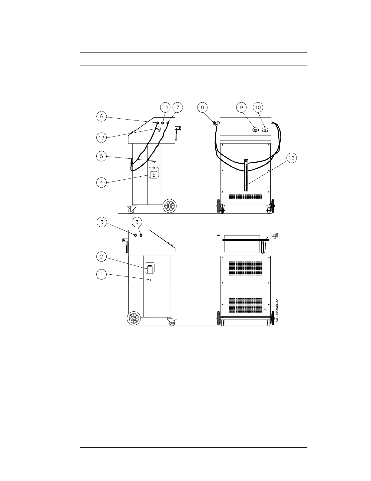
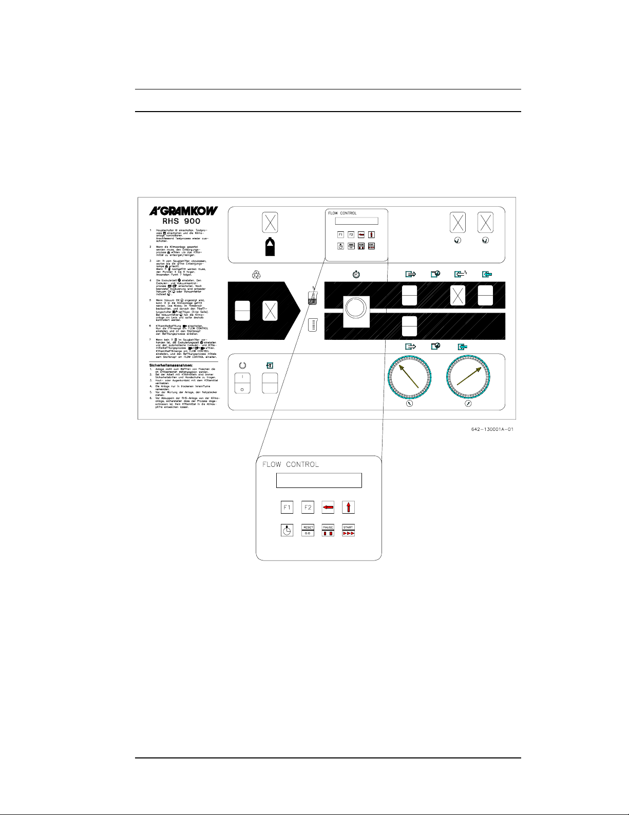
Components
1) Oil charging: Oil charging switch.
2) Oil tank
3) Parking sockets: The high and low-pressure valves can be parked here.
4) Measuring beaker: For drained oil.
5) Oil draining valve: For draining oil received from the A/C unit.
6) Connection: Low-pressure, hose connection for the low-pressure side of the
A/C unit.
C:\RHS Computer Files\Instructions\RHS\GB\642-40\0012B-01.doc 1997.09.11
RHS 900
Page 7

- 3.2 -
Components
7) Connection: High-pressure, hose connection for the high-pressure side of
the A/C unit.
8) High and low-pressure valves.
9) Low-pressure gauge: Indicates the pressure on the low-pressure side in the
test function.
10) High-pressure gauge: Indicates the pressure on the high-pressure side in
the test function.
11) Connection: For leak detector dye, or alternative type off oil.
12) Levelindication: Showing the actual level in the internal cylinder.
13) Quickcharge: For quick refilling of internal cylinder.
C:\RHS Computer Files\Instructions\RHS\GB\642-40\0012B-01.doc 1997.09.11
RHS 900
Page 8
- 3.3 -
Components
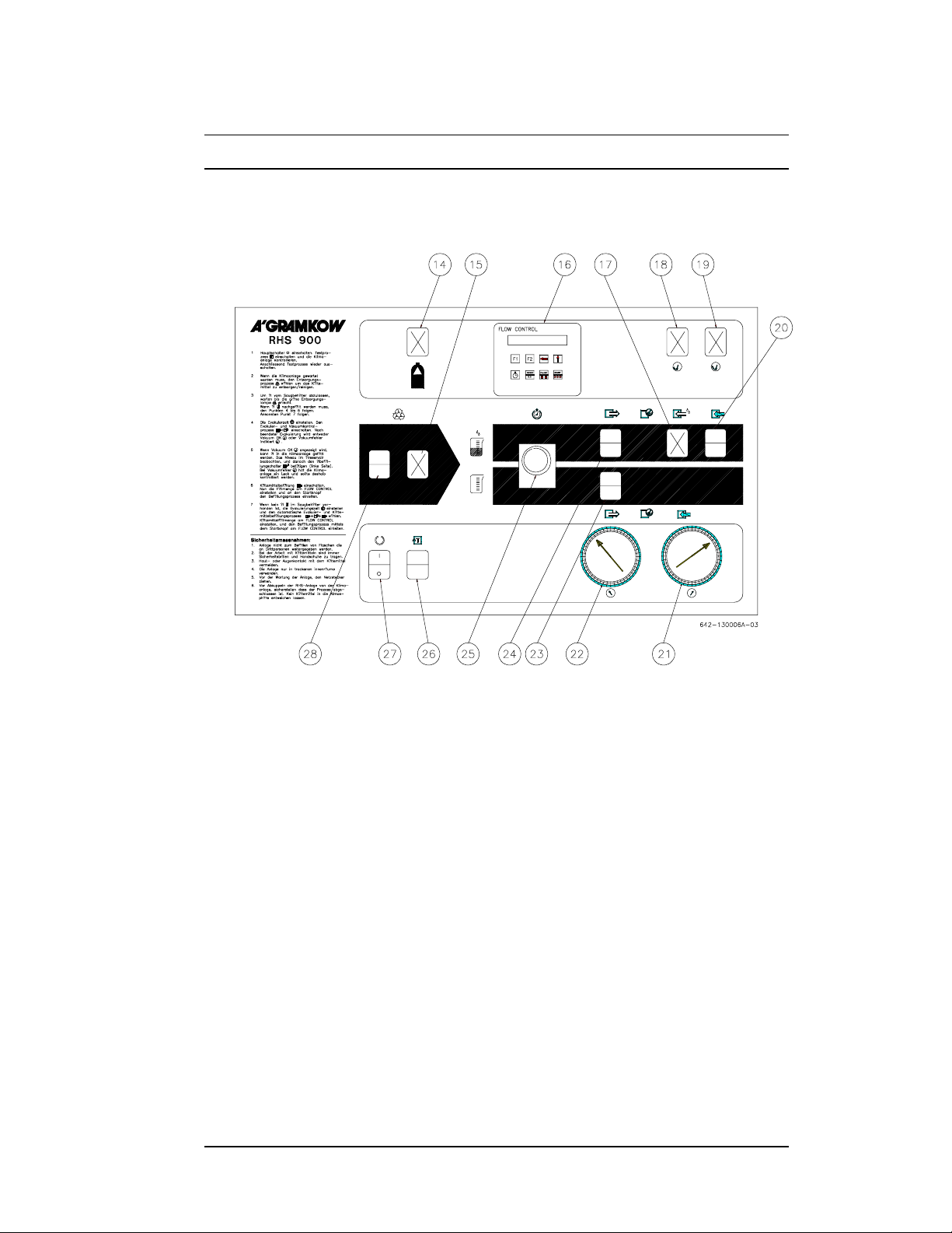
14) Charging cylinder full - lamp (yellow): lights up when the
charging cylinder is full and stops the process.
15) Compressor lamp (green): remains on for as long as the A/C unit is
subject to pressure, i.e. when vacuum reaches -0.2 bar the lamp goes
out.
16) Flow control: Display and keyboard.
17) Oil charging lamp (green): lights up when the evacuation process
is complete, and indicates oil charging. Oil charging is activated by
the switch (pos. 1).
18) Vacuum OK - lamp (white): indicates that no leakage was found
during vacuum test.
19) Vacuum defect - lamp (yellow): indicates that the vacuum has risen
to more than -0.8 bar during the vacuum test.
20) Refrigerant charging switch/lamp (green): cuts in the refrigeration
charging process and lights up when the connection is made.
21) High-pressure gauge
C:\RHS Computer Files\Instructions\RHS\GB\642-40\0012B-01.doc 1997.09.11
RHS 900
Page 9

- 3.4 -
Components
22) Low-pressure gauge
23) Automatic process switch/lamp (green): cuts in the automatic
process and lights up when the connection is made.
24) Evacuation switch/lamp (green): cuts in the evacuation process
and lights up when the connection is made. After completed
evacuation, a vacuum test is carried out automatically. The vacuum
lamps light up to indicate “OK” or “Fault”.
25) Evacuation timer: Evacuation time can be set between 0 and 60
minutes.
26) Reset/test switch/lamp (green): cuts in the test process and lights
up when the connection is made.
27) Mains switch/lamp (white): on/off switch for mains supply to
station; lights up when the connection is made.
28) Recovery switch/lamp (green): cuts in the recovery process and
lights up when the connection is made.
C:\RHS Computer Files\Instructions\RHS\GB\642-40\0012B-01.doc 1997.09.11
RHS 900
Page 10

- 4.1 -
Before use
Check the following:
- whether the station has been damaged in transit - if so, contact supplier
immediately;
- oil level in vacuum pump: it must not be below the centre of the sight glass.
If the level is too low, see section MAINTENANCE for vacuum oil
replenishment instructions;
- whether the mains supply is as stated on the station nameplate;
- whether the refrigerant in the A/C unit is as stated on the station nameplate.
Preparation:
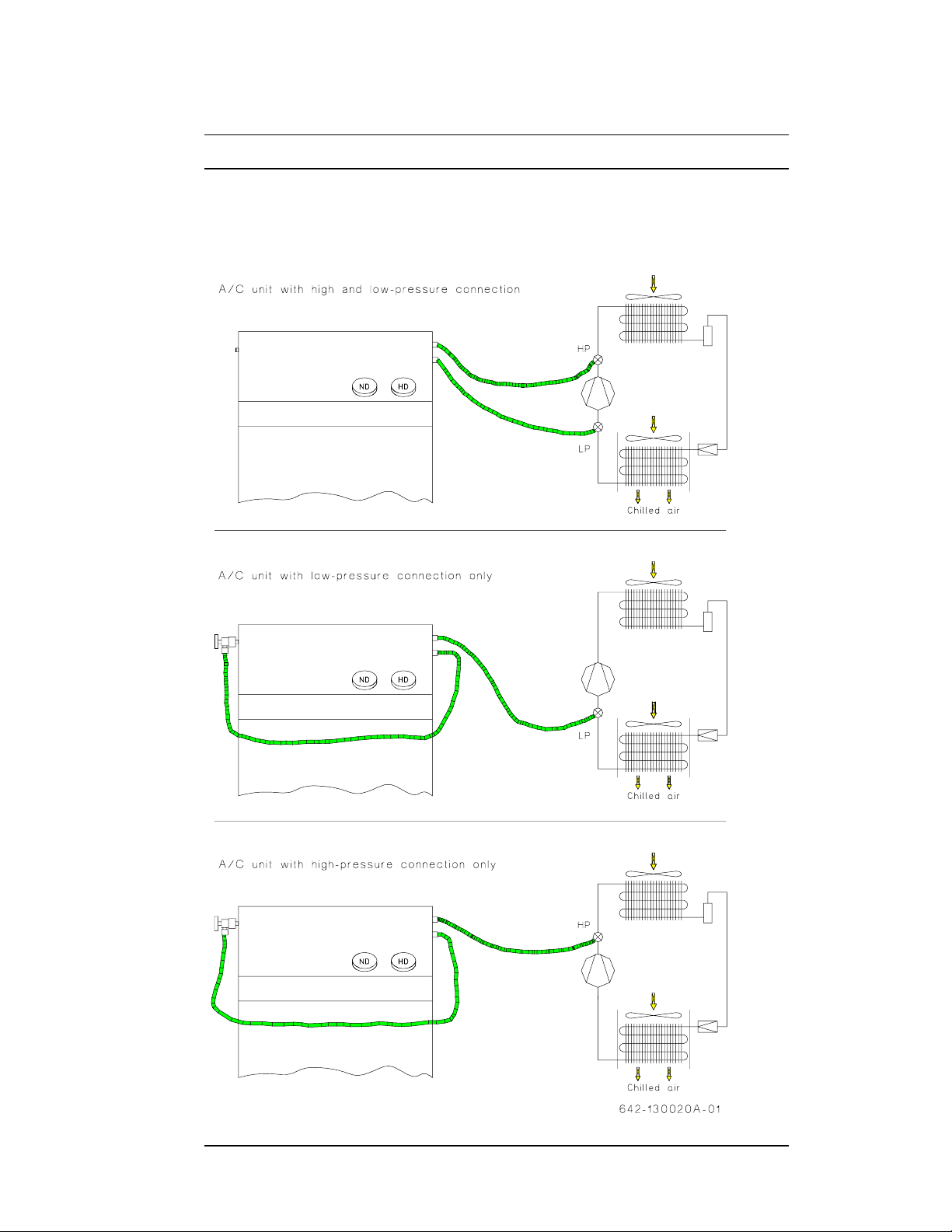
- Connect mains plug to mains supply.
- Connect the red and blue hoses to their stubs on the side of the station. Blue
hose to low-pressure side, red hose to high-pressure side. (See the next two
pages.)
- Make sure that the shut-off valves on hoses and pos. 5 are closed.
- Connect high and low-pressure hoses to their respective sides (using the
service couplings) on the A/C unit. (See the next two pages.)
- RHS 900 is now ready for operation.
C:\RHS Computer Files\Instructions\RHS\GB\642-40\0012B-01.doc 1997.09.11
RHS 900
Page 11
Before use
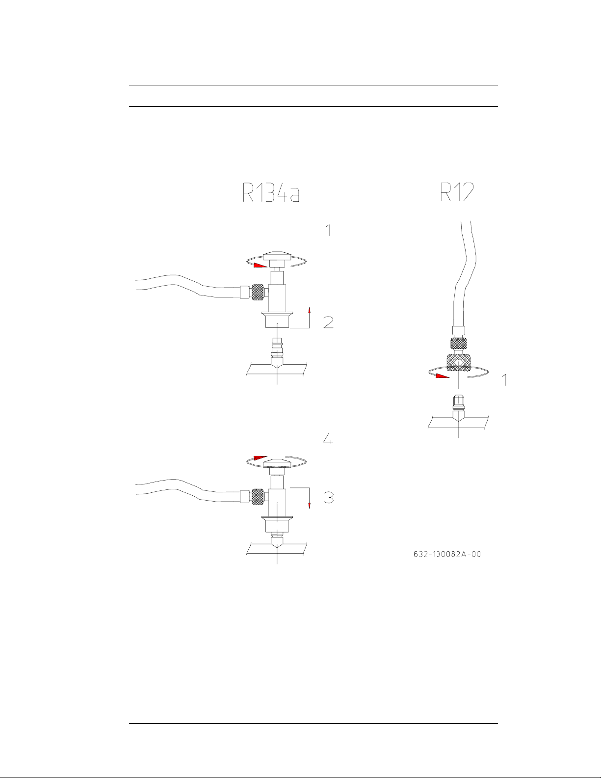
Connection of service couplings
- 4.2 -
C:\RHS Computer Files\Instructions\RHS\GB\642-40\0012B-01.doc 1997.09.11
RHS 900
Page 12
- 4.3 -
Before use
C:\RHS Computer Files\Instructions\RHS\GB\642-40\0012B-01.doc 1997.09.11
RHS 900
Page 13
- 4.4 -
Before use
Flow control - function and programming
The Flow Control system - the “FC” - monitors and controls the different
processes of RHS 900. FC can be programmed by the operator.
Variables can be altered when process switch TEST is selected (see Section 7 for
further information).
C:\RHS Computer Files\Instructions\RHS\GB\642-40\0012B-01.doc 1997.09.11
RHS 900
Page 14

- 4.5 -
Before use
The functions of the various processes are described below.
TEST: - Operation time
- Oilchange
- Maintenance time (for filter replacement)
- Variable programming.
RECYCLING:- - Display is showing processcycle and indicating the
elapsed time.
EVACUATION: - Display is showing processcycle and indicating the
elapsed time.
PRESSURERIZING: - Indicates that pressure is being built up for 2 min. , and
that the charging process will follow automatically.
CHARGING: - Monitoring/control of charging process
- Data storage
- Fault indication
- PAUSE (charging process cuts off)
Note: Operation and display texts for the various processes are described in the
operating instructions.
C:\RHS Computer Files\Instructions\RHS\GB\642-40\0012B-01.doc 1997.09.11
RHS 900
Page 15

- 5.1 -
Operating RHS 900
Test
- Open valves on service couplings.
- Activate test switch.
- Station mains switch ON (pos. 27).
- The station now performs a test function. Connect the automobile A/C unit.
The high and low-pressure gauges now indicate whether the A/C unit needs
maintenance work.
- Perform a condition diagnosis in accordance with the A/C unit supplier
instructions.
C:\RHS Computer Files\Instructions\RHS\GB\642-40\0012B-01.doc 1997.09.11
RHS 900
Page 16

- 5.2 -
0
FLOW CONTROL
T
E
1
Operating RHS 900
Test
- FLOW CONTROL function in TEST process:
On pressing the clock-key the display shows how much time remains before
servicing is necessary.
FLOW CONTROL
SERVICE TIME = 25
F1 F2
RESET STARTPAUSE
0.0
634- 130041A- 0
On pressing the clock-key and “F1” simultaneously the display shows for how
long the unit has been in operation.
OPERATION TIM E= 125
F2
RESE STAR
PAUS
0.
634-130042A-
C:\RHS Computer Files\Instructions\RHS\GB\642-40\0012B-01.doc 1997.09.11
RHS 900
Page 17

- 5.3 -
Operating RHS 900
Recovery/recycling
- Press process switch (pos. 12) RECOVERY.
- Open valves on service couplings (pos. 8).
- The compressor starts and the RECOVERY lamp (pos. 15) lights up.
- The recovery process now proceeds automatically until the A/C unit is
empty.
- The recovery process is finished when the RECOVERY lamp goes out.
Wait 5-8 minutes to ensure that the unit is completely empty.
- When the A/C unit is empty, the quantity of oil drained from the unit must
be measured. This can be done by opening the oil drain valve (pos. 5) and
allowing the oil to flow into the measuring beaker supplied. The A/C unit
must be filled with a corresponding amount of new oil. See “Oil charging”.
Follow the A/C unit supplier instructions and use only the type of oil
specified.
- At this point, if it is necessary to repair the A/C unit the service couplings
can be disconnected from the unit and servicing performed. If no repairs are
necessary, the evacuation process can be performed.
NOTE:
At the level indication Pos 12 it can before start of the recycling proces, be
noted the actual level of refrigerant. In this way, the recovered amount of
refrigant can be calculated after finishing the recovery process.
C:\RHS Computer Files\Instructions\RHS\GB\642-40\0012B-01.doc 1997.09.11
RHS 900
Page 18

- 5.4 -
Operating RHS 900
- The recovery and recycling time can be read from the FLOW CONTROL
display.
- If the A/C unit requires oil charging, the process sequence must be
EVACUATION, OIL CHARGING and REFRIGERANT CHARGING. If
oil replenishment is not necessary, AUTOMATIC PROCESS (page 5.8) can
be selected.
Evacuation
- Set the evacuation time on the timer (pos. 25).
- Press process switch (pos. 24) EVACUATION.
- If overpressure remains in the A/C unit, the vacuum pump will not start. If
this is the case, press RESET/TEST and then the RECOVERY switch. Now
wait until the compressor has created underpressure. The RECOVERY lamp
(pos. 15) will go out and EVACUATION must be pressed again.
- After evacuation is complete, a vacuum test follows automatically (leakage
test). If for a period of 3 minutes the vacuum remains lower than -0.8 bar,
the white lamp VACUUM OK lights up.
If the vacuum rises above -0.8 bar, the yellow lamp (pos. 19) lights up to
indicate VACUUM FAULT. If this is the case the leakage must be located
and repaired.
IMPORTANT! If the evacuation time selected is too short, the oil in the A/C
unit may still contain a small quantity of refrigerant. During vacuum test
such refrigerant might cause a vacuum fault even though no leakage exists.
Thus always evacuate minimum 30 minutes.
C:\RHS Computer Files\Instructions\RHS\GB\642-40\0012B-01.doc 1997.09.11
RHS 900
Page 19

- 5.5 -
Operating RHS 900
Oil charging
IMPORTANT! When the A/C unit has been charged with refrigerant, oil
charging is not possible. Oil charging must always be performed before
refrigerant charging.
Oil charging is only possible after evacuation is complete and only when the lamp
VACUUM OK (pos. 18) lights up.
Proceed as follows:
- Check to make sure that there is sufficient oil in the oil tank or replenish the
tank as described below.
- Press the oil charging switch and observe the level in the oil tank (pos. 2)
until the quantity required has been sucked into the A/C unit.
- The A/C unit is now ready for refrigerant charging. See instructions for
refrigerant charging.
Oil tank replenishment
When the level in the oil tank has reached the lower edge of the scale, oil
replenishment is necessary. Simply remove the oil tank cover and refill with oil.
C:\RHS Computer Files\Instructions\RHS\GB\642-40\0012B-01.doc 1997.09.11
RHS 900
Page 20

- 5.6 -
Operating RHS 900
Refrigerant charging
- Before the charging process, check the quantity of refrigerant necessary for
the A/C unit concerned. This information can be found on a nameplate in
the vehicle engine compartment.
- Press process switch (pos. 20) REFRIGERANT CHARGING.
- If PAUSE is indicated, push the RESET /0.0 button and following the
STARt-button to accept it.
- Key in the charging quantity required:
- The value of each numeral can be changed with the arrow-up key.
- Use the arrow-left key to move to the numeral to be changed, then use
the arrow-up key to change the value of that numeral.
C:\RHS Computer Files\Instructions\RHS\GB\642-40\0012B-01.doc 1997.09.11
RHS 900
Page 21

- 5.7 -
Operating RHS 900
- The charging process must be cut in with the START key.
- The charging process can be monitored on the display.
- If the process has to be stopped for a short period, press the PAUSE key.
- When the process is to be cut in again, press the START key.
- If the entire process is to be annulled, first press the PAUSE key and then
the RESET key. Now press the START key to confirm the annulment.
C:\RHS Computer Files\Instructions\RHS\GB\642-40\0012B-01.doc 1997.09.11
RHS 900
Page 22

- 5.8 -
Operating RHS 900
For further information on trouble shooting and GAS, BLOCK-ALARM etc., see
Section 7.
- It is now possible to check whether the A/C unit has been charged with the
correct quantity of refrigerant. To do this, start the unit and then read off
high and low pressure from the appropriate unit pressure gauges. The
correct pressures are given in the A/C unit supplier instructions.
- When charging is complete, wait 30 seconds before disconnecting quick-
coupling hoses from the A/C unit.
- As hoses will contain refrigerant residue, drain them by closing the service
hose valves and by pressing the process switch RECOVERY. The compressor will then automatically empty refrigerant from the hoses.
NOTE:
To guarantie the charging accuracy, the charging amount lost in the service
hoses, must be compensated. The loses are depending on variables such as
length of the hoses and ambient temperature.
Automatic process
When it is not necessary to charge the A/C unit with oil, AUTOMATIC
PROCESS can be selected. Evacuation, vacuum test and refrigerant charging will
then be performed automatically:
- Set the evacuation time on the timer (pos. 25).
- Press process switch (pos. 23) AUTOMATIC.
- If pressure remains on the A/C unit, the vacuum pump will not start! If this
is the case, press RESET/TEST (pos. 26) and then RECOVERY SWITCH
(pos. 12) and wait until the compressor has built up underpressure (green
recovery lamp pos. 15 goes out). AUTOMATIC can then be reactivated.
- The required quantity of refrigerant must now be entered in the Flow Con-
trol (see description under process REFRIGERANT CHARGING).
- When evacuation is complete, a vacuum test follows automatically (leakage
test!). If within 3 minutes the vacuum stays below -0.8 bar the lamp
VACUUM OK lights up and REFRIGERANT CHARGING follows
automatically.
C:\RHS Computer Files\Instructions\RHS\GB\642-40\0012B-01.doc 1997.09.11
RHS 900
Page 23

- 5.9 -
Operating RHS 900
- If, however, vacuum rises above -0.8 bar the yellow lamp indicates
VACUUM FAULT (pos. 19) and no refrigerant is charged.
- If in any case refrigerant is to be charged, refrigerant charging can be started
by activating the CHARGING switch.
- Before the actual charging process starts, the display will be indicating
“ PRESS. RIZING” in 2 minutes, where pressure is build up.
NOTE:
If the charging cylinder needs to be drained or replenished, connect the high
pressure service coupling to an external refrigerant bottle, (use the delivered
adapter if necessary). Open the high pressure valve on the RHS unit and the
service coupling.
If the charging cylinder must be drained, select the CHARGING process, (make
sure the refrigerant bottle can hold the amount).
If the charging cylinder must be replenished, select the RECYCLING process.
Also open the QUICKCHARGE-valve (pos.13), and wait till the desired amount
has been filled into the cylinder. Opening the Quickcharge valve will speed up the
process,- but remember to close the valve again during normal Recycling process,
otherwise the refrigerant quality can not be guaranteed.
Charging of Leakdetector Dye
The RHS900 is equipped with a third conection (pos. 11), wich can be used for
charging leakdetector dye or another oiltype if needed:
- Connect the oilcharging bottle (pos.B) or the Tracer Kit (pos.C) to the
connection pos.11, and wait untill the Evakuation process has been
completed.
- When using the oilcharging bottle , follow the instruction on the bottle.
When using the Tracer Kit, first connect a Tracer on the Kit. Then open the
valve, until the colored dye has disapeared from the Tracer. Then close the
valve again.
C:\RHS Computer Files\Instructions\RHS\GB\642-40\0012B-01.doc 1997.09.11
RHS 900
Page 24

- 6.1 -
Maintenance
29) Acid filter.
30) Filter drier.
31) Charging stub.
32) Charging stub.
33) Oil level vacuum pump.
34) Oil draining plug.
35) Nut.
C:\RHS Computer Files\Instructions\RHS\GB\642-40\0012B-01.doc 1997.09.11
RHS 900
Page 25

- 6.2 -
Maintenance
To observe the warranty on RHS 900, all components used for maintenance must
be identical to those in the service set, see Section 9
To ensure problem-free operation of RHS 900, the station must be maintained in
accordance with the following:
The power supply to the station must be switched off.
For each 25 operating hours:
The vakuumpump oil in time absorbs moisture, which in the end gives bad
vacuum level. Therefore the oil must be changed frequiently. It will be indicated
in the FLOWCONTROL when to change the oil. After 25 operating hours OIL
CHANGE will blink for 2 min. in the display. Resetting is done automatcally.
Change oil as follows:
- Place an oil cup below the oil draining plug Pos. 34, and loosen the plug.
Let the old oil flow into the oil cup.
- Take off the oil charging stub Pos. 32.
- Mount the oil draining plug again, and pure in new oil into the oil charging
stub Pos 32, untill the oil level can be seen in the center of the sight glass
Pos. 33.
For each 75 operating hours:
Via the FLOW CONTROL it is possible to see when maintenance is necessary by
simply pressing the clock-key on the FLOW CONTROL during the test process.
The FLOW CONTROL gives an alarm 5 hours before maintenance is due.
SERVICE will flash for 10 seconds in the display.
On reaching 75 hours of operation, SERVICE flashes for 2 minutes in the display.
After maintenance is complete, the number of operating hours to the next
maintenance must be set at zero as follows:
C:\RHS Computer Files\Instructions\RHS\GB\642-40\0012B-01.doc 1997.09.11
RHS 900
Page 26

- 6.3 -
Maintenance
C:\RHS Computer Files\Instructions\RHS\GB\642-40\0012B-01.doc 1997.09.11
RHS 900
Page 27

- 6.4 -
Maintenance
The condenser surface must be kept clean:
- Remove the rear panel of the station (4 screws).
- Clean the condenser with compressed air and perhaps a soft brush. Be
careful not to bend the fins since this would reduce the air flow and impair
condenser capacity.
- Replace rear panel.
Check the oil level in the vacuum pump:
- Oil level check: Start the evacuation process and allow it to run for a few
minutes. Switch off the process and wait for one minute and check then the
oil leviel in the sight glass (pos. 33). Replenish with oil if below the center
of the sight glass.
- Remove cap (pos. 32) to replenish vacuum pump.
- Replenish (slowly) with vacuum oil to the correct level.
- Replace cap.
Check oil level in compressor:
− Switch on the mains switch and press the recovery switch.
− Wait until the underpressure has reached 0 bar and switch off the main
switch. Do not wait, until the RECOVERY/RECYCLING-lamp goes out otherwise the pressure will be built up again in the evaporator.
− Unsrew the cap of the oil fill stub (pos 31).
− The oil level should be seen at the oil fill stub.
− When necessary, recharge the oil using the syringe supplied - up to the
mentioned level. Each time an amount is injected, wait 5 minutes to allow
the oil to ‘settle’.
− Screw cap on oil fill stub.
C:\RHS Computer Files\Instructions\RHS\GB\642-40\0012B-01.doc 1997.09.11
RHS 900
Page 28

- 6.5 -
Maintenance
For each 75 operating hours:
Replace acid filter (pos. 28)
- Remove front panel (4 screws).
- Replace filter by loosening the two 3/8" flare nuts and fit new filter. Use
only new filters fitted with protective caps on connections and make sure
the filter is oriented correctly (arrow pointing downwards).
Replace filter drier (pos. 29)
- Remove filter by first loosening end unions. Slowly loosen nuts (pos. 35)
and take out filter.
- Draw insulation off filter drier.
- Draw insulation on the new filter drier.
- Refit the new filter on station and connect unions.
On replacing filter driers a small quantity of refrigerant escapes - therefore
follow the appropriate safety precautions.
C:\RHS Computer Files\Instructions\RHS\GB\642-40\0012B-01.doc 1997.09.11
RHS 900
Page 29

- 7.1 -
Flow control - programming
The following programming is possible:
1) Display text language
2) Contrast/illumination of display background
The following variables for the charging process can be programmed:
1) The additional quantity of refrigerant to be charged to compensate for the
quantity in the hoses.
The following faults can be set at zero in the charging process:
1) Gas alarm
2) Block alarm
The processes that can be changed are described in the following:
C:\RHS Computer Files\Instructions\RHS\GB\642-40\0012B-01.doc 1997.09.11
RHS 900
Page 30

Flow control - programming
Changing the language:
- 7.2 -
C:\RHS Computer Files\Instructions\RHS\GB\642-40\0012B-01.doc 1997.09.11
RHS 900
Page 31

- 7.3 -
Flow control - programming
Changing contrast/illumination of display background.
C:\RHS Computer Files\Instructions\RHS\GB\642-40\0012B-01.doc 1997.09.11
RHS 900
Page 32

- 7.4 -
Flow control - programming
Compensation for refrigerant still in the charging hoses during charging.
An extra stroke corresponds to approx. 5 g.
The factory setting is 25 g corresponding to the maintenance hose supplied with
the station, and an ambient temp. Of 20
o
C.
Resetting of Gasalarm/Block Alarm
C:\RHS Computer Files\Instructions\RHS\GB\642-40\0012B-01.doc 1997.09.11
RHS 900
Page 33

- 7.5 -
Flow control - programming
C:\RHS Computer Files\Instructions\RHS\GB\642-40\0012B-01.doc 1997.09.11
RHS 900
Page 34

- 7.6 -
Flow control - programming
If the gas alarm cannot be turned into OFF position the charging cylinder is
probably full. Shift to Process draining/recycling and connect refrigerant bottle.
If the block alarm cannot be turned into OFF position the valve on high pressure
hose is closed or the hose is blocked. Check hose gaskets or contact the supplier.
C:\RHS Computer Files\Instructions\RHS\GB\642-40\0012B-01.doc 1997.09.11
RHS 900
Page 35

- 8.1 -
Specifications
General:
Supply voltage: See nameplate
Amperage: See nameplate
Power consumption: See nameplate
Starting current: See nameplate
Weight: 95 kg
Dimensions: 1030 x 670 x 800 mm
Test function:
High-pressure gauge: 0 to 34 bar
Low-pressure gauge: -1 to 8 bar
Recovery/recycling process:
Refrigerant: See nameplate
Oil level measurement: Drain at side of station, measuring beaker
supplied
Recycling capacity: 4 kg/h (3-5 vehicles/h)
Non-condensable gases: Automatic blow-off, temperature-compensated
Suctionaccumolator: 2,4 L.
Charging capacity: 7 Kg. Optional 14 Kg.
Charging accuracy: ±2% with 40 cm. hoses.
Dryer: Exchangeable (after 75 operating houers)
Evacuation process:
Suction capacity: Approx. 3 m
Vacuum level: < 0.5 mbar absolute
Oil charging: Oil reservoir : 250 ml
Operating panel
3
/h
C:\RHS Computer Files\Instructions\RHS\GB\642-40\0012B-01.doc 1997.09.11
RHS 900
Page 36

- 8.2 -
Specifications
Mains switch - white: Power supply cut in
Test switch - green: Test process in function
Recovery switch - green: Recovery process in function
Recovery lamp - green: Pressure in A/C unit
Evacuation switch - green: Evacuation process in function
Oil charging switch - green: Oil charging in process
Refrigerant charging switch - green: Refrigerant charging in process
Automatic process switch - green: Evacuation of A/C unit, vacuum check
and refrigerant charging in process
Vacuum check lamp - green: Vacuum OK
Vacuum check lamp - yellow: Vacuum fault / leakage
Charging cylinder lamp - yellow: Cylinder full
C:\RHS Computer Files\Instructions\RHS\GB\642-40\0012B-01.doc 1997.09.11
RHS 900
Page 37

- 8.3 -
Specifications
Service and maintenance
Acid filter: Replaceable, 3/8" SAE
Oil filter: 0.6 µm (built into oil separator)
Filter drier: Replaceable, (capacity 75 hours or 300 kg
refrigerant)
Compressor oil level: Sight glass + charging stub
Vacuum pump oil level: Sight glass + charging stub
Safety equipment: Mechanical safety valve on charging cylinder
Overfilling protection on charging cylinder
Suction pressure regulator on compressor
High-pressure control on compressor
Code number of RHS 900: See nameplate
C:\RHS Computer Files\Instructions\RHS\GB\642-40\0012B-01.doc 1997.09.11
RHS 900
Page 38

- 9.1 -
Service set
Quantity Description Code no.
1
1
2
0.25 l
0.25 l
To order complete service set - state code no. (see nameplate).
Acid filter
Filter drier
Gasket for filter drier
Compressor oil - mineral
Oil for vacuum pump
069-2910127
069-7480044
065-7751920
290-0001250
290-0001272
C:\RHS Computer Files\Instructions\RHS\GB\642-40\0012B-01.doc 1997.09.11
RHS 900
Page 39

- 10.1 -
Accessories
Qty Description Code no.
1 Operating instructions, English 642-400012A
1 Service coupling, high pressure (R134a) 290-7480095
1 Service coupling, low pressure (R134a) 290-7480096
1 Service coupling (R12) 066-7390234
1 Service hose, blue (R134a) = 72" 634-140002A
1 Service hose, red (R134a) = 72" 634-140001A
1 Service hose, blue (R12) = 180 cm 080-4665015
1 Service hose, red (R12) = 180 cm 080-4665017
1 Service hose, yellow (R12) = 90 cm 080-4665002
1 Gasket for R134a hose, gasket outside dia. 8.3 mm 087-7481010
1 Gasket for R134a hose, gasket outside dia. 9.6 mm 087-7482130
1 O-ring for R134a hose 087-7481341
1 O-ring for R134a hose, gasket outside dia. 14 mm 087-7470210
1 Gasket for R12 hose, gasket outside dia. 8.5 mm 066-7750950
1 Injector, 60 ml 290-5390268
1 Oil beaker, 250 ml 290-0780096
1 Oil beaker, 225 ml, with handle 146-7489012
1 Label, English operating instructions 642-420010A
1 Oilcharging bottle, 300 ml German instruction 642-040003A
1 Oilcharging bottle, 300 ml Englisch instruction 642-040003B
1 Tracer Kit, R134a 643-040002A
1 Tracer Kit, R12 634-040007A
C:\RHS Computer Files\Instructions\RHS\GB\642-40\0012B-01.doc 1997.09.11
RHS 900
Page 40

- 11.1 -
Trouble shooting
Test process
Problem Fault Remedy
Pressure gauge shows no
pressure
Pressure gauge shows
the same reading all the
time
Recovery process:
Problem Fault Remedy
Recovery process does
not start - green recovery
lamp does not light up
Recovery process does
not stop
Recovery process runs
only for a short period
1. and 2. Valve not opened
2. No refrigerant in A/C unit
1. A/C unit defective
2. A/C unit not cut in
1. RHS 900 not cut in
2. Valves not opened
3. No refrigerant in A/C unit
4. System pressure is 16 bar
5. Internal cylinder full
6. Internal component fault
1. Oil drain valve not closed
2. A/C unit leakage
3. Internal component fault
1. Valves on service couplings not opened
2. System pressure is 16 bar
3. Internal cylinder full
4. Internal component fault
1. Open high and low-pressure valves on service
couplings
2. Repair A/C unit.
1. Empty A/C unit and repair
2. Cut in A/C unit
1. Cut in RHS 900
2. Open high and low-pressure valves on
service couplings
3. Repair A/C unit
4. Contact RHS 900 supplier
5. Empty cylinder
6. Contact RHS 900 supplier
1. Close valve
2. Contact RHS 900 supplier
3. Contact RHS 900 supplier
1. Open valves
2. Contact RHS 900 supplier
3. Empty cylinder
4. Contact RHS 900 supplier
C:\RHS Computer Files\Instructions\RHS\GB\642-40\0012B-01.doc 1997.09.11
RHS 900
Page 41

- 11.2 -
Trouble shooting
Evacuation process:
Problem Fault Remedy
Vacuum pump does not
run
Vacuum pump runs but
does not build up enough
vacuum
Charging process:
Problem Fault Remedy
No refrigerant flow 1. High-pressure valve on service coupling
Lamps "Vacuum OK"
and "Vacuum fault" light
up together
1. RHS 900 not cut in
2. Overpressure in A/C unit
3. Internal component fault
1. Service couplings not fitted correctly
2. A/C unit defective/leaking
3. Internal component fault
not opened
2. Internal component fault
1. Solenoid valve Y14 in RHS 900 leaking 1. Replace valve or contact RHS 900 supplier
1. Cut in RHS 900
2. Cut in recovery process
3. Contact RHS 900 supplier
1. Fit service couplings correctly
2. Repair A/C unit
3. Contact RHS 900 supplier
1. Open valve
2. Contact RHS 900 supplier!
C:\RHS Computer Files\Instructions\RHS\GB\642-40\0012B-01.doc 1997.09.11
RHS 900
Page 42

Mecanical diagram
- 12.1 -
Pos. no. location
642-120001A-01
C:\RHS Computer Files\Instructions\RHS\GB\642-40\0012B-01.doc 1997.09.11
RHS 900
Page 43

Electrical diagram:
- 12.2 -
Pos. no. location
642-120002A-01
C:\RHS Computer Files\Instructions\RHS\GB\642-40\0012B-01.doc 1997.09.11
RHS 900
Page 44

- 12.3 -
Pos. no. location
2) Check valve 10) Check valve
3) Suction accumulator 11) Check valve
5) Acid filter 17) Check valve
6) Check valve M1) Compressor
8) Oil filter M2) Condenser/Fan
9) Filter drier M3) Vacuum pump
C:\RHS Computer Files\Instructions\RHS\GB\642-40\0012B-01.doc 1997.09.11
RHS 900
Page 45

- 13.1 -
Appendixes
Example of trouble shooting in an A/C unit:
Conditions:
1. Ambient temperature 30-35°C (86-95°F)
2. Motor speed 2000 rpm
3. A/C unit temperature setting Maximum
Under the above conditions the pressure values for an intact A/C unit will be
as follows during the TEST process:
High pressure 15 bar
Low pressure 2 bar
Follow the TEST process as in Section 5:
- Connect service couplings to A/C unit.
- Close high and low-pressure valves on RHS 500.
- Open service coupling valves.
- Start in A/C unit.
- Now the station will perform a test function.
Perform a condition diagnosis for the A/C unit in accordance with supplier
instructions.
- Stop A/C unit after the test process has been completed.
C:\RHS Computer Files\Instructions\RHS\GB\642-40\0012B-01.doc 1997.09.11
RHS 900
Page 46

- 13.2 -
Appendixes
Test - 1:
High pressure 8 - 9 bar
Low pressure Approx.
Fault/Problem Symptom Possible cause Remedy
Unsatisfactory
refrigeration
Test - 2:
High pressure Approx.
Low presure Approx.
Fault/Problem Symptom Possible cause Remedy
Unsatisfactory
refrigeration
Test - 3:
C:\RHS Computer Files\Instructions\RHS\GB\642-40\0012B-01.doc 1997.09.11
RHS 900
0.8 bar
Conditioned air not
cold
Air bubbles in sight
glass
20 bar
2.5 bar
Leakage in A/C unit
Insufficient refrigerant
in A/C unit
Insufficient condenser
cooling
Fan does not run
Condenser performance
impaired by oil or dirt
deposits
Insufficient oil in A/C
unit (compressor friction)
Refrigerant overcharge
Locate leak and
repair
Replenish with
refrigerant
Clean condenser
Repair fan
Clean condenser
Replenish oil
check the refrigerant
quantity in the A/C unit empty the A/C unit,
evacuate and recharge thr
correct quantity
If none of these remedies
are successful, check the
refrigerant quantity in the
A/C unit - empty the A/C
unit, evacuate and
recharge
Page 47

- 13.3 -
Appendixes
High pressure Approx.
Low pressure Approx.
Fault/Problem Symptom Possible cause Remedy
Periodic
disturbances in
A/C unit
Test - 4:
High pressure Approx.
Low pressure Approx.
Fault/Problem Symptom Possible cause Remedy
Little or no
refrigeration from
A/C unit
7 - 15 bar
1.5 bar
Varying pressure on
high and low-pressure sides
6 bar
-0.3 bar
Hoses before or after expansion valve
or filter drier covered with moisture
or ice
Moisture in A/C unit
causes ice formation on
expansion valve resulting in reduced output,
ore filter drier
saturated.
Expansion valve or
filter drier blocked with
ice because of moisture
in A/C unit
Empty A/C unit,
evacuate and recharge. After the
recovery process,
replace filter drier.
If necessary, remove
expansion valve,
clean it and refit or
replace as necessary.
Disconnect A/C
unit, wait a few
minutes and then
empty the unit,
evacuate and
recharge
C:\RHS Computer Files\Instructions\RHS\GB\642-40\0012B-01.doc 1997.09.11
RHS 900
Page 48

- 13.4 -
Appendixes
Test - 5:
High pressure Approx.
Low pressure Approx.
Fault/Problem Symptom Possible cause Remedy
Unacceptable
refrigeration
Test - 6:
High pressure Approx.
Low pressure Approx.
Fault/Problem Symptom Possible cause Remedy
A/C unit does not
refrigerate
19 - 20 bar
2.5 bar
Ice or moisture on
hoses on low
pressure/suction side
of A/C unit
7 - 10 bar
4 - 6 bar
Pressure on lowpressure side too
high or pressure on
high-pressure side
too low
Expansion valve
defective or sensor
placed incorrectly.
Expansion valve opens
too much.
Internal compressor
leakage
Check expansion
valve sensor
placing.
Replace expansion
valve.
Repair or replace
compressor
C:\RHS Computer Files\Instructions\RHS\GB\642-40\0012B-01.doc 1997.09.11
RHS 900
Page 49

- 13.5 -
Appendixes
Pressure vessel declaration
We confirm herewith that the condition of the pressure vessel in this unit
conforms to regulations laid down by the appropriate authorities:
Suction accumulator, pos. 3:
Manufacturer: A'GRAMKOW A/S
Augustenborg Landevej 19
DK-6400 Sønderborg
Denmark
Type: 642-010017A
Permissible working pressure: PS = 25 bar
Permissible working temperature:
Volume: V = 1.53 litres
Oil separator, pos. 8:
Manufacturer: AC & R Components
Chatham, Ill.
USA
Type: S-5920F
Permissible working pressure: PS = 31.05 bar
Permissible working temperature:
Volume: V = 0.83 litres
-40/70°C
10/120°C
C:\RHS Computer Files\Instructions\RHS\GB\642-40\0012B-01.doc 1997.09.11
RHS 900
Page 50

- 13.6 -
Appendixes
Filter drier, pos. 9:
Manufacturer: RTI Technologies Inc.
Type: 026-80044-00
Permissible working pressure: PS = 31.05 bar
Permissible working temperature:
Volume: V = 0.83 litres
Charging cylinder, pos. 13
Manufacturer: Henry Valve (UK)
Type: 642-100027B
Permissible working pressure: PS = 25 bar
Permissible working temperature:
Volume: V =7.0 litres
10/120°C
-20/120°C
C:\RHS Computer Files\Instructions\RHS\GB\642-40\0012B-01.doc 1997.09.11
RHS 900
 Loading...