

Page 1
OPERATION & MAINTENANCE MANUAL
RHS730
Refrigerant Handling Station
RTI Technologies, Inc.
4075 East Market Street
P.O. Box 3099
York, Pennsylvania USA 17402
717-840-0678 (Ext. 259)
Web: www.rtitech.com
E-mail: tech@rtitech.com
Manual P/N 035-81031-00 (Rev A)
Page 2

Two Modes of Operation
The RHS730 can be used to perform semi-automatic
procedures or run in a fully automatic mode.
The following Table of Contents will direct you to the
proper sections for detailed operating instructions.
TABLE OF CONTENTS - RHS730
Before Using the RHS730 ...................... 2
Safety Precautions............................ 2
How the RHS730 Operates ..................... 3
Setup ...................................... 4
Semi-Automatic Procedures
Fill Charge Cylinder ........................... 5
Recycle .................................... 6
Drain Recovered Oil........................... 7
Manual Air Purge ............................. 7
Deep Vacuum ............................... 8
Charge ..................................... 9
Fully Automatic Procedure
Automatic...................................10
Programming & Maintenance
Access Stored Data ...........................13
Set Over Charge Amount .......................14
Calibrate Weight Scale.........................15
Scheduled Maintenance ........................16
Filter Maintenance ............................16
Change Filters ...............................16
Parts Identification ............................17
Solenoid & Contactor Identification ...............19
Technical Support 800-468-2321
Page 3

BEFORE USING THE RHS730
Check for any shipping damage. Place a claim with carrier if damage is discovered. DO NOT USE A DAMAGED UNIT.
These general instructions describe normal operation and maintenance situations encountered with the RHS730. Failure
to read and comply with these instructions or any one of the limitations noted herein can result in serious injury and/or
property damage.
A few minutes spent reading these instructions can make an operator aware of dangerous practices to avoid and
precautions to take for his own safety and the safety of others. The instructions should not be interpreted to anticipate every
possible contingency.
The RHS730 should not be operated or serviced by any person who has not read all the contents of this manual.
It is the responsibility of the owner/user to operate the RHS730 in accordance with all specifications and laws which may
apply.
A regular schedule of inspection of the RHS730 should be established and records maintained with special attention given
to Hoses, Vacuum Pump Oil Level and Filters.
SAFETY PRECAUTIONS
Recycle and Charge only the refrigerant for which the machine is configured.
Wear safety glasses and protective gloves. Refrigerant has a very low boiling point and can cause frostbite.
Follow the RHS730 operating procedures sequentially to avoid prematurely disconnecting hoses or opening valves which
may release refrigerant to the atmosphere.
Do not expose the RHS730 to moisture or operate in wet areas.
Use the RHS730 in locations with mechanical ventilation that provides at least four air changes per hour.
Hoses used with the RHS730 must have shutoff devices within 12 inches (30 centimeters) of the connection point to the
A/C System to minimize the introduction of Non-Condensable Gas (Air) into the RHS730 and the release of refrigerant
when being connected or disconnected.
Disconnect power before performing any maintenance or service on the RHS730.
Connect the RHS730 to a properly grounded receptacle. Do not over load the circuit (20 amp minimum).
Avoid using an extension cord with the RHS730. If necessary, use a good condition three wire, grounded, #14 AWG (2.0
2
) or larger extension cord of the shortest possible length (maximum 25 ft. - 8 m).
mm
Do not connect the RHS730 to the liquid side of any A/C System with a capacity greater than 4 lbs (1.8 Kg.) Refrigerant
in A/C Systems having larger capacities must be recycled from the vapor side only.
Never connect the Red or Blue Hose of the RHS730 to the Liquid Port of a Cylinder of Refrigerant to fill the Charge
Cylinder. Doing so may cause the Compressor to fail and void the warranty.
Avoid breathing refrigerant or lubricant vapor or mist. Exposure may irritate eyes, nose and throat. If accidental system
discharge occurs, ventilate work area before continuing.
Additional health and safety information may be obtained from refrigerant and lubricant manufacturers.
SPECIAL CONSIDERATIONS WITH R134a
R134a has been shown to be nonflammable at ambient temperature and atmospheric pressure. However, tests under
controlled conditions have indicated that at pressures above atmospheric and with air concentrations greater than 60
percent by volume, R134a can form combustible mixtures.
While it is recognized that an ignition source is also required for combustion to occur, the presence of combustible mixtures
is a potentially dangerous situation and should be avoided.
Under no circumstances should any equipment be pressure tested or leak tested with air and R134a mixtures. Do not use
compressed air (shop air) for leak detection in R134a systems.
Page 2
Page 4
HOW THE RHS730 OPERATES
The RHS730 is microprocessor controlled with a menu-driven user interface. All functions are performed by entering a few
simple key strokes and following the prompts on the display. The on-board charge cylinder is mounted on a load cell. The
weight of refrigerant in the charge cylinder is electronically displayed.
The RHS730 has a Fill Cylinder feature which allows refrigerant to be transferred directly into the charge cylinder without
going through the normal Recycle mode. This feature allows the RHS730 charge cylinder to be re-filled directly from a
cylinder of new refrigerant. The process automatically stops at approximately 20 lbs (9 kg).
The RHS730 recycles refrigerant in a true single-pass through the filters and stores the refrigerant in the charge cylinder
where it’s immediately available for use. This process automatically stops at 24 lbs (11 Kg) or when a 15 In-Hg (-0.5 Bar)
vacuum is sensed in the A/C system.
The RHS730 pauses for a minimum factory-set default of two minutes for out gassing and cold refrigerant to raise the
pressure back up to 3 psig (0.2 Bar) at which time the recycle process will start again and reset the Recycle Hold Timer.
When the pressure does not rise to reset the timer during the two minute pause, the display will indicate that the process
is complete. The Recycle Hold Timer can be changed every time a Recycle procedure is run.
Longer recycle hold times should be selected on colder days or when servicing an A/C system with a large liquid capacity.
Increasing this value may increase total time to recycle while decreasing the time may result in an incomplete recycling
of refrigerant from the A/C system.
Refer to the table below for guidelines on setting the Recycle Hold Timer. The value entered is stored in the memory of
the RHS730 and becomes the default value each time it is set.
0
Temperature Less than 50
Recycle Hold Time 10 minutes 5 minutes 2 minutes
F (100 C) 500 F (100 C) to 800 F (26.50 C) Greater than 800 F (26.50 C)
Non-condensable gases (air) are vented automatically during the recycle process.
The amount of refrigerant recycled is displayed at the end of the procedure. This value is added to the total amount
recycled and is stored in the memory of the RHS730.
A 7 CFM vacuum pump draws on both the high and low hoses, ensuring c omplete evacuation of the A/C system. The
amount of time that the vacuum pump has been programmed to run will count down on the display. The value entered is
stored in the memory of the RHS730 and becomes the default value each time it is set.
The low pressure gauge can be monitored to see a rise in A/C system pressure. When programmed to do so, the RHS730
will pause and start a count up timer indicating how long the vacuum pump has been off, thus allowing the operator to
determine if a vacuum leak is present based on increasing pressure over time. A rapid rise in pressure indicates the
presence of a large leak that should be repaired. A slow rise in pressure may simply indicate that a longer recycle hold time
or vacuum time value should have been entered.
A relatively constant vacuum reading over a long period of time (less than 2 In-Hg [0.05 Bar] rise over ten minutes) is the
most accurate way to check for vacuum leaks.
The RHS730 can also be programmed to pause to allow oil to be added to the A/C system after vacuuming and prior to
charging.
Charging is done from the on board charge cylinder. An integrated heater automatically engages whenever charging
occurs. The A/C capacity is entered on the Keypad. The value entered is stored in the memory of the RHS730 and
becomes the default value each time it is set. As refrigerant leaves the RHS730, the display will show an increasing weight
up to the programmed charge amount plus a factory-set one ounce (0.03 Kg) over charge amount necessary for
compensation of refrigerant loss in the hoses.
The over charge amount can be changed to accommodate different operating conditions. The amount of refrigerant
charged is added to the total amount charged and stored in the memory of the RHS730.
The high side red hose can be connected to the low side port o f the RHS730 for charging to the low side of
vehicles with only a low side port. Follow the vehicle manufacturer’s charging procedure when charging to
the low side to avoid damaging the A/C system compressor.
Page 3
Page 5
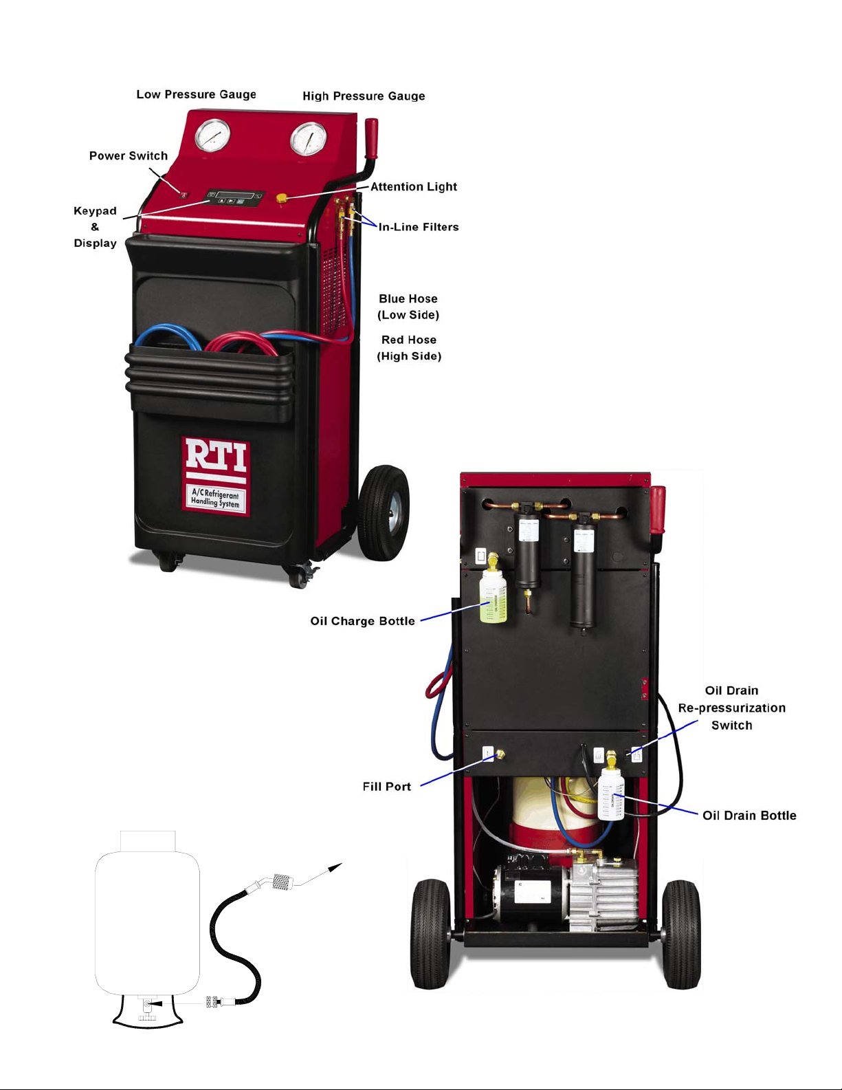
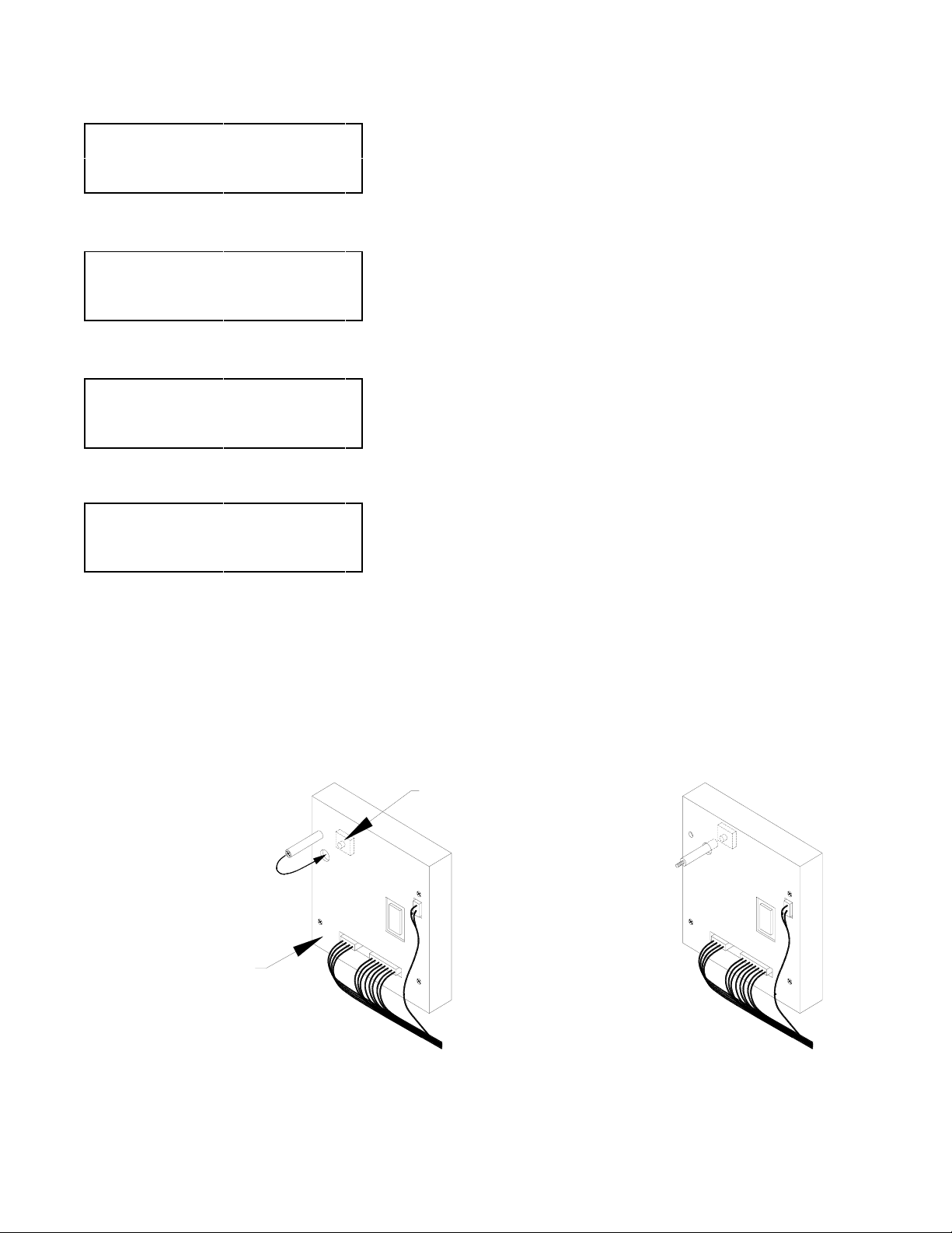
SETUP
New
Refrigerant
Anti-Blowback
Valve
To Fill Port
Page 4
Page 6
WEIGHT= XX.X LB
AUTOMATIC
?
>>>>
WEIGHT= XX.X LB
FILL CYLINDER
?
FILL CHARGE CYLINDER
1. Connect a cylinder of new refrigerant to the Fill Port on the rear of the
5
RHS730 as shown on Page 4. Anti-blowb ack Valve must connect to
the RHS730. Turn the cylinder up-side-down. Turn Main Power Switch on.
The display will show WEIGHT= XX.X LB AUTOMATIC?
2. Press the
5
CYLINDER?
> key four times to display WEIGHT= XX.X LB FILL
5.
5.
ENTER
START
?
ENTER
WEIGHT= XX.X LB
COMPRESSOR ON
FILL COMPLETE
FILLED= XX.X LB
ENTER
*
HIGH PRESSURE
SEE MANUAL
3. Press the ENTER key. The display will read START?
4. Open the valve on the cylinder of new refrigerant.
5. Press the ENTER key to start filling the RHS730.
5
6. Close the valve on the refrigerant cylinder.
7. Press the ENTER key to return to the Main Menu.
5
The Display will read WEIGHT= XX.X LB COMPRESSOR ON.
When the weight is approximately 20 lbs (9 kg) the RHS730 will turn
OFF, the display will read FILL COMPLETE FILLED=XX.X LB
(the amount of refrigerant removed from the cylinder). The Attention
Light will turn on.
The RESET button on the keypad can be pressed at any time to stop
the Fill Cylinder procedure prior to it filling and shutting off
automatically.
This procedure may be slow or fail to work if the internal
charge cylinder pressure is higher than the pressure in the
cylinder of new refrigerant. Check and purge air if necessary
(See Page 7).
Also, try putting a heat belt on the new refrigerant cylinder.
5.
5
**
CYLINDER FULL
GO TO CHARGE
5
* While filling the charge cylinder, this screen will display periodically
concurrent with the Attention Light turning on. This is normal and
nothing to be concerned about. The screen will return to normal after
a few seconds.
** This screen will display if the charge cylinder fills to capacity,
approximately 24 lbs (11 Kg). If this occurs, the weight can be lowered
using the Charge procedure on Page 9. This must be done before the
RHS730 can be used to recycle more refrigerant. Press the ENTER
key to return to the Main Menu.
Notes:
It may be desirable to skip this procedure for large capacity or multiple A/C systems where recharge will not be
done between successive recycling procedures.
The RHS730 uses 22 lbs (10 Kg) of refrigerant when filling the first time. If the cyli nder of new refrigerant is
emptied, the RHS730 will appear to stop filling (the weight displayed will stop increasing) and w ill stay in this
condition until the RESET key is pressed.
The RHS730 will use 1.1 Lb (0.5 Kg) more refrigerant than the displayed value the very first time it is used or after
performing a Calibration Procedure in order to prime the internal components.
The RHS730 Charge Cylinder can also be filled from the GAS or VAPOR side of a cylinder by following the Recycle
procedure on Page 6.
The yellow hose can be disconnected from the Fill Port on the rear of the RHS730 and reconnected to either the
Blue (Low side) or Red (High Side) hose connection port on the side of the RHS730 to allow recycling any
refrigerant remaining in the yellow hose using the Recycle procedure on Page 6.
Page 5
Page 7
WEIGHT= XX.X LB
AUTOMATIC
?
>
WEIGHT= XX.X LB
RECYCLE
1. See RHS730 Setup on Page 4. Turn Main Power Switch on.
5
The display will show WEIGHT= XX.X LB AUTOMATIC?
2. Attach Red and Blue Hoses to the A/C System per the vehicle
manufacturer's instructions. Open the Red and Blue Hose Valves.
5
RECYCLE
?
ENTER
RECYCLE HOLD
TIME XX MIN
>< ENTER
START
ENTER
WEIGHT= XX.X LB
COMPRESSOR ON
?
WEIGHT= XX.X LB
COMPRESSOR OFF
AMOUNT RECYCLED=
XX.X LB
3. Press the
5
and press the ENTER key. The Display will read RECYCLE HOLD TIME
XX MIN
5
4. Press the
to a different field. Press the ENTER key to accept the value. The Display
5
5
will then read START?
5. Press the ENTER key to start recycling.
6. Close the Red and Blue Hose Valves and disconnect the hoses from the
A/C system.
> key one time to display WEIGHT= XX.X LB RECYCLE? 5
5.
The Recycle Hold Time is the amount of time that the RHS730 waits
for out-gassing or for the pressure in the A/C System being recycled to
rise enough to automatically restart the recycling process. The
minimum time is two minutes. The value entered is stored in the
memory of the RHS730 and is displayed as the default value next time.
> key to change the value of the field. Press the < key to move
5.
The Display will read WEIGHT= XX.X LB COMPRESSOR ON. The
RHS730 will recycle refrigerant from the A/C system and automatically
cycle OFF when a vacuum is sensed. This vacuum level can be seen
on the Low Pressure Gauge. The Display will read WEIGHT= XX.X LB
COMPRESSOR OFF.
A small quantity of refrigerant will probably remain in the A/C system
as observed by an increasing pressure on the Low Pressure Gauge.
The RHS730 will automatically cycle on to continue recycling
refrigerant if pressure rises to a preset level. This automatic cycling will
repeat, resetting the Recycle Hold Timer each time. When the RHS730
remains off for the duration of the Recycle Hold Timer value entered in
Step 4, the Display will read AMOUNT RECYCLED= XX.X LB
the Attention Light will turn on.
5 and
ENTER
DRAIN RECOVERED
OIL NOW!
ENTER
*
HIGH PRESSURE
SEE MANUAL
**
CYLINDER FULL
GO TO CHARGE
7. P ress the ENTER key. The Display will read DRAIN RECOVERED OIL
NOW!
procedure on Page 7.
8. Press the ENTER key to return to the Main Menu.
5. Drain any recovered oil using the Drain Recovered Oil
5
* This screen will display if there is an internal fault. Turn the RHS730
Main Power Switch off. Contact RTI Technical Support.
** This screen will display if the charge cylinder fills to capacity of
approximately 24 lbs (11 Kg.). If this occurs, the weight must be
lowered using the Charge procedure on Page 9 before the RHS730
5
can be used to recycle more refrigerant. Press the ENTER key to
return to the Main Menu.
Page 6
Page 8

DRAIN RECOVERED OIL
Oil is separated from the recycled refrigerant and MUST be removed following EACH Recycle procedure to determine the
amount (if any) required to add into the A/C system as follows:
1. Turn Main Power Switch on. The display will show WEIGHT= XX.X LB AUTOMATIC?
2. Press and hold the Oil Drain Re-pressurization Switch on the rear of the RHS730 for five seconds.
3. Slowly open the valve on the Oil Drain Bottle to drain any oil which may have been removed from the A/C System.
Unless the A/C System had previously been overfilled, the RHS730 will typically not remove enough oil to make
replenishment necessary.
4. Close the valve on the Oil Drain Bottle.
5. Press and hold the Oil Drain Re-pressurization Switch for five seconds. This allows any residual Non-Condensable
Gas to be re-circulated for reprocessing during the next recycle procedure.
Note: The Drain Recovered Oil procedure may be done while the RHS730 is performing the Deep Vacuum
procedure on the next page.
5.
WARNING
Failure to perform the Drain Oil procedure after
every recycle procedure will cause the RHS730 to
eventually fail.
Repair of the RHS730 to correct this problem is
not covered by warranty.
Manual Air Purge
The RHS730 purges air (also referred to as Non-Condensable Gas) automatically. There may be occasions where an extra
purge may be desired. One instance is when the Fill Charge Cylinder process seems slow. The following steps allow a
manual purge.
1. Turn Main Power Switch on. The display will show WEIGHT= XX.X LB AUTOMATIC?
2. Slowly open the valve on the Oil Drain Bottle.
3. Press and hold the Oil Drain Re-pressurization Switch on the rear of the RHS730 for five seconds.
4. Close valve on the Oil Drain Bottle.
5. Press and hold the Oil Drain Re-pressurization Switch for five seconds.
5.
Page 7
Page 9
WEIGHT= XX.X LB
DEEP VACUUM
AUTOMATIC
?
>>
WEIGHT= XX.X LB
VACUUM
ENTER
*
?
A/C HAS PRESSURE
GO TO RECYCLE
ENTER VACUUM
TIME XX MIN
>< ENTER
1. See RHS730 Setup on Page 4. Turn Main Power Switch on.
5
2. Attach Red and Blue Hoses to the A/C System per the vehicle
manufacturer's instructions. Open the Red and Blue Hose Valves.
3. Press the
5
5
4. Press the
5
and press the ENTER key. The Display will read ENTER VACUUM TIME
XX MIN
* This screen will display if the RHS730 senses a pressure in either the
to a different field. The value entered must be greater than zero. Press the
ENTER key to accept the value. The Display will read PERFORM LEAK
TEST? Y/N
> key two times to display WEIGHT= XX.X LB VACUUM? 5
5.
Red or Blue Hose. When this occurs, the A/C System must be emptied
using the Recycle procedure on Page 6. Press the ENTER key to
return to the Main Menu.
> key to change the value of the field. Press the < key to move
5.
PERFORM LEAK
TEST
?
Y/N5
< ENTER
ADD OIL
?
Y/N5
< ENTER
START
ENTER
TIME LEFT=XX MIN
PUMP ON
?
PUMP OFF XX MIN
CONTINUE
?
5. Press the
not the RHS730 pauses at the end of Vacuum procedure so that a vacuum
leak can be detected in the A/C system. Press the ENTER key to accept
the Yes or No choice. The value entered is stored in the memory of the
RHS730 and is displayed as the default value next time. The Display will
read ADD OIL? Y/N
6. Press the
not the RHS730 pauses at the end of the Vacuum procedure (or Leak
Test) to allow adding of oil to the A/C system. Press the ENTER key to
accept the Yes or No choice. The value entered is stored in the memory
of the RHS730 and is displayed as the default value next time. The Display
will read START?
5
7. Press the ENTER key to start the Vacuum procedure.
8. If a Vacuum Leak Check was selected by choosing Y in Step 5 the display
will read PUMP OFF XX MIN CONTINUE?
turn on. The elapsed time since the Vacuum Pump turned off will count up
on the display. An increasing pressure on the Low Pressure Gauge is
evidence of a vacuum leak in the A/C system. Press the RESET key to
5
return to the Main Menu (so the leak can be repaired) or press the ENTER
key to proceed to Add Oil if selected in Step 6.
< key to move the cursor between Y and N to select whether or
5.
< key to move the cursor between Y and N to select whether or
5.
The Vacuum Pump will turn on, the display will read TIME LEFT=XX
MIN PUMP ON. The minutes remaining will count down on the
display. The Vacuum Pump will turn off when the display reads zero
minutes.
5 and the Attention Light will
ENTER
ADD OIL NOW
CONTINUE
ENTER
?
9. If Add Oil was selected by choosing Y in Step 6 the Display will read ADD
5
OIL NOW CONTINUE?
Fill the Oil Charge Bottle. Open the valve on the Oil Charge Bottle and
leave it open until the correct amount of oil has left the Oil Charge Bottle.
Close the valve on the Oil Charge Bottle and press the ENTER key to
return to the Main Menu. (The oil drawn in will be charged with the
refrigerant during the Charge procedure on Page 9).
5. The Attention Light will turn on.
Page 8
Page 10

WEIGHT= XX.X LB
CHARGE
AUTOMATIC
?
>>>
WEIGHT= XX.X LB
CHARGE
ENTER
?
ENTER CHARGE
AMOUNT= XX.X LB
>< ENTER
*
LOW LEVEL
FILL CYLINDER
GO TO
,
1. See RHS730 Setup on Page 4.Turn the Main Power Switch on.
5
2. Attach the Red and Blue Hoses to the A/C system per the vehicle
manufacturer's instructions and open the Red and Blue Hose Valves.
3. Determine the refrigerant capacity of the A/C system to be charged.
5
4. Press the
5. Press the
5
5
and press the ENTER key. The Display will read ENTER CHARGE
AMOUNT= XX.X LB
to a different field. The value entered must be greater than zero. Press the
ENTER key to accept the value. The value entered is stored in the
memory of the RHS730 and is displayed as the default value next time.
The Display will read CHECK HOSES
* This screen will display if the RHS730 charge cylinder contains less
refrigerant than the entered value. When this occurs, the charge
cylinder should be filled using the Fill Cylinder procedure on Page 5.
Press the ENTER key to return to the Main Menu.
1 oz = 0.02835 Kg 1 Lb = 0.45359 Kg
> key three times to display WEIGHT= XX.X LB CHARGE? 5
5.
>key to change the value of the field. Press the < key to move
5.
CHECK HOSES
ENTER
WEIGHT= XX.X LB
CHARGING
CHARGE COMPLETE
EVAC HOSES
ENTER
Refrigerant is usually charged to the high side of an A/C system
through the Red Hose. The Blue Hose can be connected to the
high side port (where Red Hose is normally connected) if it is
5
desired to charge to the low side of the A/C system. This should
only be done if the vehicle manufacturer specifies charging to the
low side.
Do not turn on the A/C system.
SAE compliant refrigerant handling stations, like the RHS730,
charge refrigerant in the liquid phase. Adding liquid refrigerant to
a running A/C system may cause immediate A/C compressor
failure.
5
6. Press the ENTER key to start charging.
The Display will read WEIGHT= XX.X LB CHARGING as refrigerant
leaves the Charge Cylinder. The weight displayed will increase from
zero to the charge amount entered in Step 5 plus a one ounce (0.03
Kg) over charge set at the factory to compensate for refrigerant left in
the hoses (See Set Over Charge Amount on Page 14 to change the
default value). When the RHS730 has finished, the Display will read
CHARGE COMPLETE EVAC HOSES
turn on.
5 and the Attention Light will
7. Press the EN TER key to return to the Main Menu. The A/C system can
now be turned on and tested by monitoring the High and Low Pressure
Gauges.
8. Close the Red and Blue Hose Valves. Disconnect hoses from the A/C
system and go to Page 6 (Recycle) to evacuate the refrigerant from the
hoses.
Page 9
Page 11
WEIGHT= XX.X LB
AUTOMATIC
ENTER
?
RECYCLE HOLD
TIME XX MIN
1. See RHS730 Setup on Page 4. Turn Main Power Switch ON.
2. Attach the Red and Blue Hoses to the A/C System per the vehicle
5
5
manufacturer's instructions and open the Red and Blue Hose Valves.
3. Determine the refrigerant capacity of the A/C System to be charged.
1 oz = 0.02835 Kg 1 Lb = 0.45359 Kg
4. Press the ENTER key when the Display reads WEIGHT= XX.X LB
AUTOMATIC?
5.
5. The Display will read RECYCLE HOLD TIME XX MIN
>< ENTER
ENTER VACUUM
TIME XX MIN
>< ENTER
PERFORM LEAK
TEST
?
Y/N5
< ENTER
ADD OIL
?
Y/N5
< ENTER
ENTER CHARGE
AMOUNT= XX.X LB
>< ENTER
*
LOW LEVEL
GO TO
,
5
5. Press the
6. Press the
7. Press the
5
8. Press the
The Recycle Hold Time is the length of time that the RHS730 waits
for out-gassing or for the pressure in the A/C system being recycled
to rise enough to automatically restart the recycling process. The
minimum value is two minutes. The value entered is stored in the
memory of the RHS730 and is displayed as the default value next
time.
> key to change the value of the field. Press the < key to move
to a different field. Press the ENTER key to accept the value. The Display
will read ENTER VACUUM TIME XX MIN
5.
> key to change the value of the field. Press the < key to move
to a different field. Press the ENTER key to accept the value. The Display
will read PERFORM LEAK TEST? Y/N
5.
< key to move the cursor between Y and N to select whether
or not the RHS730 pauses at the end of Vacuuming so that a vacuum leak
can be detected in the A/C system. Press the ENTER key to accept the
Yes or No choice. The value entered is stored in the memory of the
RHS730 and is displayed as the default value next time. The Display will
read ADD OIL? Y/N
5.
< key to move the cursor between Y and N to select whether
or not the RHS730 pauses at the end of Vacuum procedure (or Vacuum
Leak Test) to allow the adding of oil to the A/C system. Press the ENTER
key to accept the Yes or No choice. The value entered is stored in the
memory of the RHS730 and is displayed as the default value next time.
The Display will read ENTER CHARGE AMOUNT= XX.X LB
5.
FILL CYLINDER
ENTER
CHECK HOSES 5
ENTER
START
?
ENTER
AUTOMATIC
9. Press the
5
to a different field. The value entered must be greater than zero. Press the
ENTER key to accept the value. The value entered is stored in the
memory of the RHS730 and is displayed as the default value next time.
The Display will read CHECK HOSES
* This screen will display if the RHS730 charge cylinder contains less
10. Press the ENTER key. The Display will read START?
> key to change the value of the field. Press the < key to move
5.
refrigerant than the entered value. When this occurs, the charge
cylinder should be filled using the Fill Cylinder procedure on Page 5.
Press the ENTER key to return to the Main Menu.
Do not turn on the A/C system
SAE compliant refrigerant handling stations, like the RHS730,
5
charge refrigerant in the liquid phase. Adding liquid refrigerant to
a running A/C System may cause immediate A/C compressor
failure.
11. Press the ENTER key to start the RHS730 Automatic sequence.
5.
Page 10
Page 12
WEIGHT= XX.X LB
AUTOMATIC - Continued
COMPRESSOR ON
WEIGHT= XX.X LB
COMPRESSOR OFF
*
HIGH PRESSURE
SEE MANUAL
**
CYLINDER FULL
GO TO CHARGE
5
The Display will read WEIGHT= XX.X LB COMPRESSOR ON. The
RHS730 will recycle refrigerant from the A/C system and automatically
cycle off when a vacuum is sensed. This vacuum level can be seen on
the Low Pressure Gauge. The Display will read WEIGHT= XX.X LB
COMPRESSOR OFF.
* This screen will display if there is an internal fault. Turn the RHS730
Power Switch off. Contact RTI Technical Support.
** This screen will display when the charge cylinder fills to capacity,
approximately 24 lbs (11 Kg.) If this occurs, the weight can be
lowered using the Charge procedure on Page 9 before the RHS730
can be used to recycle more refrigerant. Press the ENTER key to
return to the Main Menu.
A small quantity of refrigerant will probably remain in the A/C system as
observed by an increasing pressure on the Low Pressure Gauge. The
RHS730 will automatically cycle on to continue recycling refrigerant if
pressure rises to a preset level. This automatic cycling will repeat,
resetting the Recycle Hold Timer each time.
When the RHS730 remains off for the duration of the Recycle Hold Timer
value entered in Step 5 the Display will change to one of the following
two steps:
TIME LEFT=XX MIN
PUMP ON
PUMP OFF XX MIN
CONTINUE
ENTER
?
1 - The value entered for vacuum time in Step 6 was zero - the Display
will read WEIGHT= XX.X LB CHARGING. Go to Step 15.
2 - The value entered for vacuum time in Step 6 was greater than zero -
the Display will read TIME LEFT=XX MIN PUMP ON. Go to Step 12.
12 The vacuum pump will turn on. The Display will read TIME LEFT=XX
MIN PUMP ON and the minutes remaining will count down on the
Display.
Once the vacuum pump is running, any recovered oil must be
drained and measured as follows:
12.1 Press and hold the Oil Drain Re-pressurization Switch on the rear
of the RHS730 for five seconds.
12.2 Slowly open the valve on the Oil Drain Bottle to drain any oil which
5
13. If a Vacuum Leak Check was selected by choosing Y in Step 7 the
may have been removed from the A/C System.
12.3 Close the valve on the Oil Drain Bottle.
12.4 Press and hold the Oil Drain Re-pressurization Switch for five
seconds. This causes any residual Non-Condensable Gas to be
re-circulated for reprocessing during the next recycle procedure.
The Vacuum Pump will turn off when the Display reads zero minutes.
Display will read PUMP OFF XX MIN CONTINUE?
Light will turn on. (Skip to Step 14 if Vacuum Leak Check was not
selected).
5 and the Attention
The elapsed time since the Vacuum Pump stopped will count up on the
Display. An increasing pressure on the Low Pressure Gauge indicates
a vacuum leak in the A/C system. Press the ENTER key to continue with
the Automatic sequence or RESET to return to the Main Menu in case of
a vacuum leak.
Page 11
Page 13

ENTER
AUTOMATIC - Continued
ADD OIL NOW
CONTINUE
ENTER
?
WEIGHT= XX.X LB
CHARGING
RECYCLED=XX.X LB
EVAC HOSES
ENTER
DRAIN RECOVERED
OIL NOW!
5
14. If Add Oil was selected by choosing Y in Step 8 the Display will read
ADD OIL NOW CONTINUE?
5
5
to Step 15 if Add Oil was not selected).
Fill the Oil Charge Bottle. Open the valve on the Oil Charge Bottle and
leave it open until the correct amount of oil (measured in Step 12) has left
the Oil Charge Bottle. Close the valve on the Oil Charge Bottle and press
the ENTER key to continue. The oil drawn in will be charged with the
refrigerant during the Charge procedure.
15. If a Charge Amount greater than zero pounds was entered in Step 9 the
Display will read WEIGHT= XX.X LB CHARGING as refrigerant leaves
the Charge Cylinder. The weight displayed will increase from zero to the
Charge Amount entered plus a one ounce (0.03 KG) over charge set at
the factory to compensate for hose loss. See Set Over Charge Amount
on Page 14 to change the default value. When the RHS730 has finished,
the Display will read RECYCLED=XX.X LB EVAC HOSES and the
Attention Light will turn on.
16. Press the ENTER key. The Display will read DRAIN RECOVERED OIL
NOW!. This is a reminder that oil must be drained after every recycle
procedure. If it was drained in Step 12 above it is not necessary to drain
it here. If it was not drained in Step 12, drain any recovered oil as follows:
16.1 Press and hold the Oil Drain Re-pressurization Switch on the rear
of the RHS730 for five seconds.
16.2 Slowly open the valve on the Oil Drain Bottle to drain any oil which
may have been removed from the A/C System.
5 and the Attention Light will turn on. (Skip
ENTER
16.3 Close the valve on the Oil Drain Bottle.
16.4 Press and hold the Oil Drain Re-pressurization Switch for five
seconds. This causes any residual Non-Condensable Gas to be
re-circulated for reprocessing during the next recycle procedure.
WARNING
Failure to perform the Drain Oil procedure after
every recycle procedure will cause the RHS730 to
eventually fail.
Repair of the RHS730 to correct this problem is not
covered by warranty.
17. Press the ENTER key to return to the Main Menu. The A/C System can
now be turned on and checked by monitoring the High and Low Pressure
Gauges.
18. Close the Red and Blue Hose Valves. Disconnect them from the A/C
System and go to Page 6 (Recycle) to evacuate the refrigerant from the
hoses if desired.
Page 12
Page 14
WEIGHT= XX.X LB
AUTOMATIC
?
5
ACCESS STORED DATA
1. Turn the Main Power Switch on.
>>>>> ENTER
WEIGHT= XX.X LB
SETUP
ENTER
FILTER HOURS=
XX.X HOURS
?
>
TOTAL RECYCLED=
XXXX.X KG
>
2. Press the
5
3. Press the
4. Press the
5. Press the
> key five times to display WEIGHT= XX.X LB SETUP? 5 and
then press the ENTER key. The Display will read FILTER HOURS= XX.X
HOURS.
See Filter Maintenance (Page 15) for the procedure to change the filters.
The normal Filter Change Interval is after every 25 hours.
Press and hold the
CHANGE FILTERS
< key and press the RESET key to remove the
5 message.
> key. The Display will read TOTAL RECYCLED XXXX.X KG.
> key. The Display will read TOTAL CHARGED= XXXX.X KG.
> key to return to the Main Menu.
TOTAL CHARGED=
XXXX.X KG
>
Page 13
Page 15
WEIGHT= XX.X LB
SET OVER CHARGE AMOUNT
1. Remove two screws on each side to remove front cover. Remove four
screws and carefully tilt top control panel up to gain access to printed
circuit board cover.
2. Turn the Main Power Switch on.
AUTOMATIC
?
>>>>> ENTER
WEIGHT= XX.X LB
SETUP
Press Calibration Switch
?
WEIGHT= XX.X LB
CHARGING
>
OVER CHARGE
AMOUNT= X.XX KG
><ENTER
5
5
5
Refer to the figure below to locate the access hole for the Calibration
Switch which is on the underside of the Circuit Board Cover.
3. Remove the plastic Calibration Tool.
4. Press the
5. Gently press the Calibration Switch with the Calibration Tool.
The Display will read WEIGHT= XX.X LB CHARGING.
6. Press the
KG
7. Press the
to a different field. The value entered will be stored until this procedure is
run again and a new value is entered. Press the ENTER key to accept the
value. The Display will then return to the Main Menu.
8. Place the Calibration Tool in the storage hole.
9. Lower top control panel, being careful to not bend or crimp copper tubes,
and install screws. Replace the front cover.
> key five times to display WEIGHT= XX.X LB SETUP? 5 .
> key. The Display will read OVER CHARGE AMOUNT= X.XX
5.
> key to change the value of the field. Press the < key to move
1 oz = 0.02835 Kg 1 Lb = 0.45359 Kg
Calibration Tool Part No. 360-81214-00
Calibration Tool in
Storage Position
Printed Circuit
Board Cover
Calibra t io n
Switch
Calibration Tool
in Access Hole
Ready to Press
Calibra tio n Switch
Page 14
Page 16
WEIGHT= XX.X LB
AUTOMATIC
?
>>>>> ENTER
WEIGHT= XX.X LB
SETUP
?
CALIBRATE WEIGHT SCALE
1. Remove two screws on each side and remove front cover. Remove four
screws and carefully tilt top control panel up to gain access to printed
5
5
circuit board cover. Refer to the illustration on preceding page.
2. Remove Red Hose from High Side Port and connect the Blue Hose
from the High Side Port to the Vapor Port of a DOT cylinder. Use Low
Side Tank Adapter (RTI Part Number 023-80147-00). Open valve on
DOT cylinder.
3 Locate the access hole for the Calibration Switch which is on the
underside of the Circuit Board Cover.
4. Remove the plastic Calibration Tool.
Press Calibration Switch
WEIGHT= XX.X LB
CHARGING
After 15 minutes or
Press Calibration Switch
CALIBRATION
MIN WEIGHT ON
ENTER
CALIBRATION
MAX WEIGHT ON
ENTER
CALIBRATION DONE
REMOVE WEIGHT
5. Press the
6. Gently press the Calibration Switch with the Calibration Tool. The Display
will read WEIGHT= XX.X LB CHARGING.
The RHS730 charges out the contents of the Charge Cylinder. It
automatically continues to the next step after fifteen minutes. The
calibration switch can be pressed at any time during this fifteen minutes
to proceed to the next step.
7. The Display will read CALIBRATION MIN WEIGHT ON
8. Press the ENTER key. The display will read CALIBRATION MAX
5
5
5
WEIGHT ON
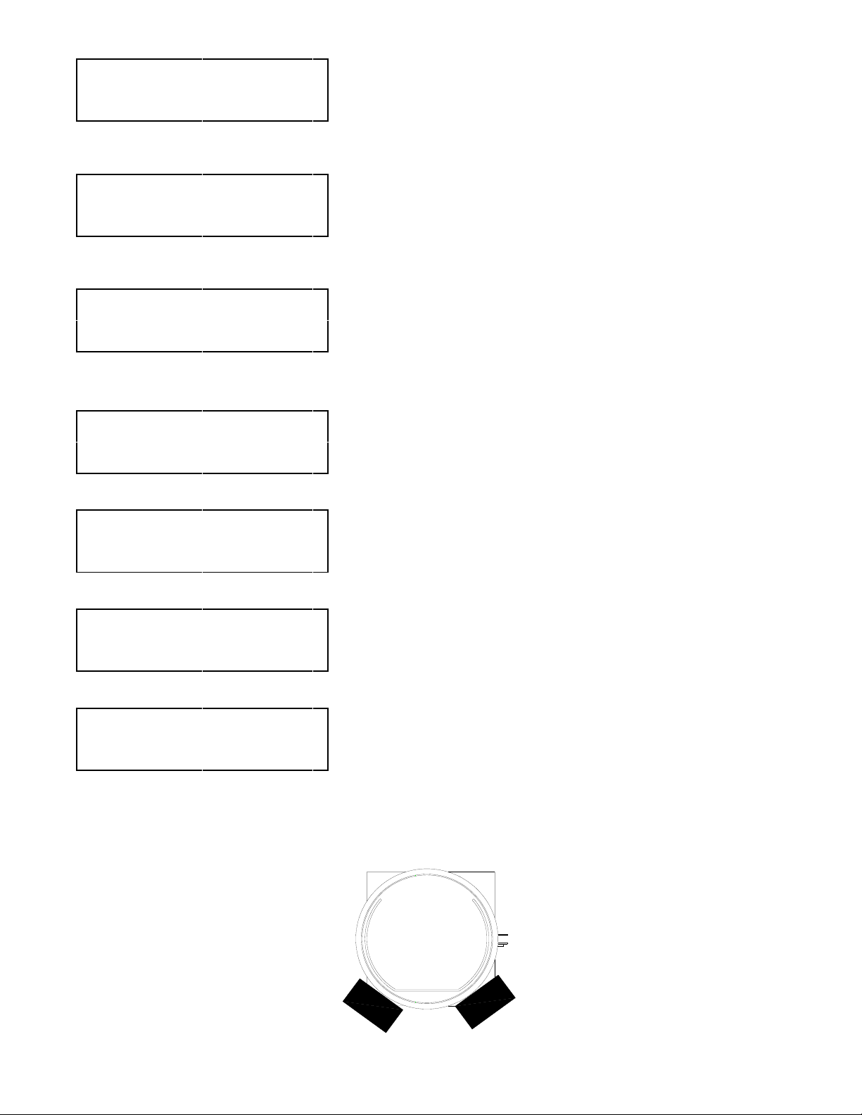
9. Place the two 5 Kg calibration weights on the square plate under the
charge cylinder as shown in the illustration below.
10. Press the ENTER key. The display will read CALIBRATION DONE
REMOVE WEIGHT
11. Press the ENTER key. The display will then read OVER CHARGE
AMOUNT= X.XX KG
12. Press the
move to a different field. The value entered will be stored until this
procedure is run again and a new value is entered. Press the ENTER key
to accept the value. The Display will then return to the Main Menu.
> key five times to display WEIGHT= XX.X LB SETUP? 5
5.
5.
5. Remove the Calibration Weights.
5.
> key to change the value of the field. Press the < key to
ENTER
OVER CHARGE
AMOUNT= X.XX KG
><ENTER
1 oz = 0.02835 Kg 1 Lb = 0.45359 Kg
13. Place the Calibration Tool in the storage hole.
14. Lower top control panel, being careful to not bend or crimp copper tubes,
5
and install screws. Replace the front cover and install screws.
Calibration Tool Part No. 360-81214-00
Calibration Weight Kit Part No. 360-81282-00
Rear
Charge
Cylinder
Calibration Weights
Page 15
Page 17

SCHEDULED MAINTENANCE
DAILY...
Check the oil level in the Vacuum Pump while the pump is running. The Vacuum Pump Oil Level Sight Glass is
visible through a hole in the Left Side Panel of the RHS730. The oil level should be at the “half-way” point of the
glass. If oil is not visible call Technical Support at 800-468-2321 extension 259.
MONTHLY...
Clean the Condenser to maintain high efficiency performance of the RHS730. Disconnect power and remove the
panel below the filters on the rear of the RHS730. Blow compressed air through the cooling fins of the Condenser
(from inside of cabinet towards the vent slots in the side panel) to remove any debris. Do not bend the fins on the
Condenser coils. Air flow will be restricted causing damage to the RHS730. Replace the panel before applying
power to the RHS730.
FILTER MAINTENANCE
The RHS730 automatically keeps track of Compressor Run Time. The Display will read CHANGE FILTERS 5 after
every 25 hours every time the program returns to the Main Menu or whenever the RHS730 is turned on as a reminder
to change the filters. Press ENTER to go to the Main Menu.
The INLET Combo Filter (left side on rear) must be changed after every 25 hours of operation.
RTI part number 026-80069-00.
The OUTLET Combo Filter (right side on rear) must be changed after every 50 hours of operation.
RTI part number 026-80077-00.
The Hours Counter is reset when the CHANGE FILTERS
changes performed to track when only the INLET Combo Filter is changed versus when both are changed.
5 message is cleared (refer to page 13). Record the filter
CHANGE FILTERS
1. Disconnect Flare Fittings from top and bottom of filters.
2. Remove mounting nuts and filters.
3. Install new Combo Filters using hardware removed in Step 2.
4. Connect Flare Fittings to top and bottom of filters.
5. Check for leaks and repair as necessary.
6. Go to Page 13, Access Stored Data, for instructions to remove the CHANGE FILTERS
5 message.
Page 16
Page 18
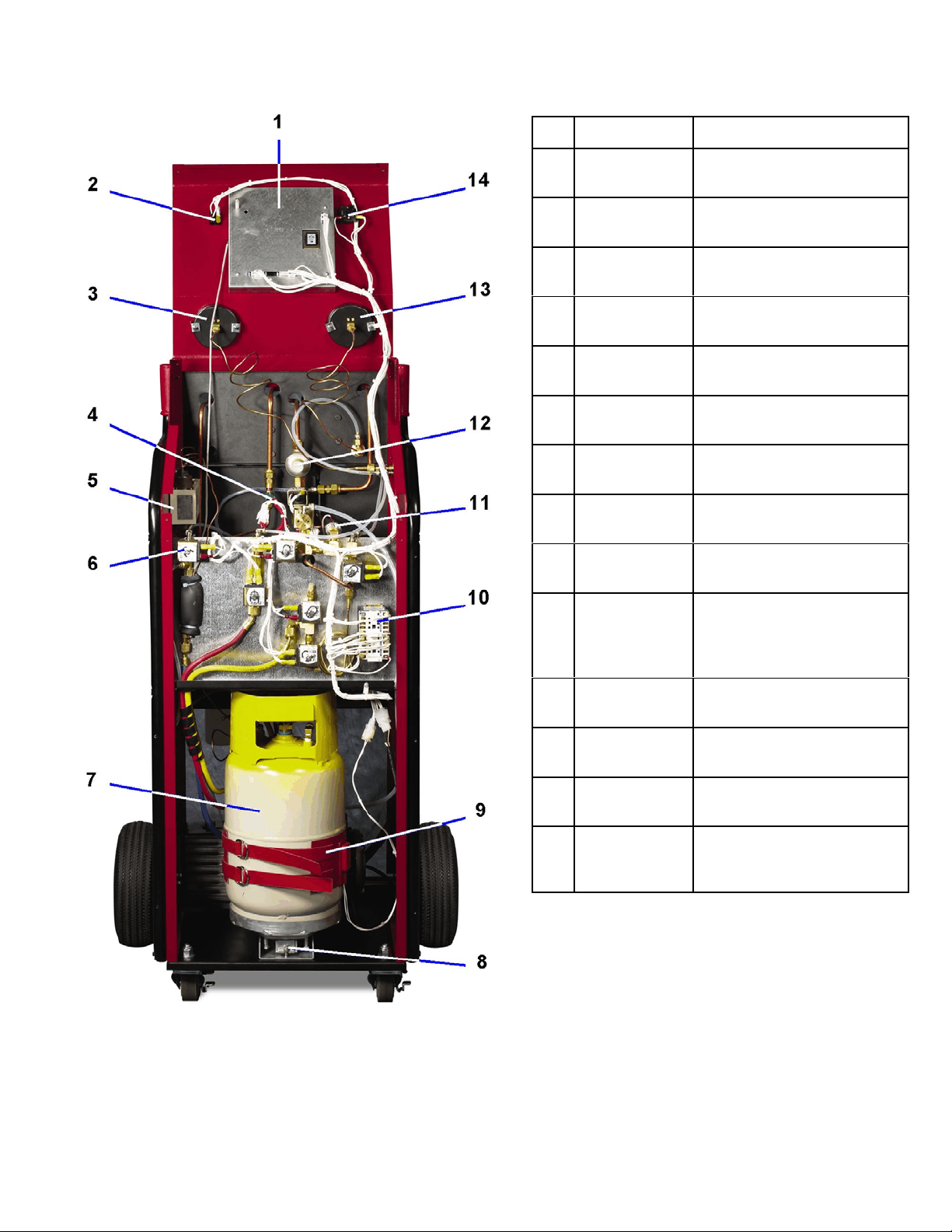
PARTS IDENTIFICATION - Front View
P/N DESCRIPTION
1 024-80097-01 Circuit Board
2 024-80040-00 Rocker Switch SPDT
3 026-80065-03 Gauge 30 InHg - 120 PSIG
4 360-81307-00 High Pressure Switch
5 360-80369-02 D/P Switch R134A
6 360-81292-00 Solenoid MOV Sub-Assy
7 360-81447-00 DOT Cylinder Assy
120V
(on-on) Amber (125V)
1/4 MFL 3.5 in.
120V
120V
30 lbs
8 031-80003-00 Load Cell Assy
9 360-81426-01 Heater Belt Assy
10 024-80037-00
025-80314-03
11 022-80050-01 Low Pressure Switch
12 022-80110-00 Expansion Valve
13 026-80071-03 Gauge 0 - 500 PSIG
14 025-80127-00
025-80191-00
Contactor ½ HP (120V)
3NC - 1NC
Varistor
3 PSIG - 15 InHg SPDT
3/8 MFL x 3/8 MFL
1/4 MFL 3.5 In.
Bulb Bayonet Base (120V)
Yellow Lens Assy
Page 17
Page 19

PARTS IDENTIFICATION - Rear View
P/N DESCRIPTION
1 026-80069-00 Combo Filter 3/8 Flare
(Short)
2 026-80208-00
026-80208-01
3 026-80077-00 Combo Filter 3/8 Flare
4 024-80035-00 Rocker Switch SPST
5 026-80207-00
026-80207-01
6 026-80229-00 Vacuum Pump - 7 CFM
10 360-81439-00 Condenser Assembly
11 360-80416-00 Fan Assembly
12 360-81670-01 Compressor Assembly
13 026-80070-00 Accumulator Assembly
Oil Charge Bottle with Valve
Oil Charge Bottle only
(Long)
Momentary On - Non-lighted
Oil Drain Bottle with Valve
Oil Drain Bottle only
120V
026-80240-00
026-80241-00
In-Line Hose Filter (R12)
In-Line Hose Filter (R134a)
Rear View - Cover Off
Page 18
Page 20

Solenoid & Contactor Identification
Page 19
 Loading...