

Page 1

A’GRAMKOW A/S
Augustenborg Landevej 19
DK-6400 Sønderborg
Denmark
A/S Reg. No. 17 12 31
Telephone: 45 74 12 36 36
Telefax: 45 74 43 36 46
Telex: 5 23 18
Bank: Den Danske Bank, No. 32 27
INSTRUCTIONS RHS 700
Recovery, Recycling, Evacuation
and Charging Station
RHS 700
C:\RHS Computer Files\Instructions\RHS\GB\645-40\0009A-01.doc 1997.03.26
RHS 700
Page 2

Contents RHS 700
1. Application
2. Safety precautions
3. Components
4. Before use
5. Test
6. Recovery/recycling
7. Evacuation
8. Charging
9. Maintenance
10. Trouble shooting
11. Service set
12. Accessories/spare parts
13. Specifications
14. Pos. no. location
15. Appendix
- 0.1 -
C:\RHS Computer Files\Instructions\RHS\GB\645-40\0009A-01.doc 1997.03.26
RHS 700
Page 3

- 1.1 -
Application
Your new RHS 700 station represents the latest in equipment for servicing airconditioning units (A/C units). The station is designed for refrigerants R12 and
R134a. It can, and must, only be used for one of these refrigerants.
RHS 700 is a test, recovery/recycling-(draining/cleaning), evacuation, oil/refrigerant charging station and is thus able to perform a total process cycle in
servicing A/C units for the automobile industry.
The recycling process is designed to follow SAE-standards J1989 and J2099 on
recycled refrigerant for A/C units.
Process operations - from test to charging - are performed by operating four
different process switches and two shut-off valves. This reduces the risk of error
operation to a minimum.
Constant monitoring ensures that the automatic process sequence does occur
correctly. Safety devices are built into the station to stop operation and indicate
faults in processes, e.g. excessively high pressure, overcharging of charging
cylinder.
During the recycling process a small quantity of oil is drained from the A/C unit.
On completion of the recovery process this quantity can be drained into a
measuring beaker. The same quantity of new oil must be filled into the A/C unit.
Refer to the A/C unit instructions and use only the type of oil specified.
The filter driers have a very high capacity (200 kg) and are easy to replace during
servicing.
A system built into the station ensures that non-condensable gases are automatically blown off and that the discharge of refrigerant to the atmosphere is kept to
a minimum.
Before using RHS 700, read these instructions carefully to ensure that the processes are performed correctly.
C:\RHS Computer Files\Instructions\RHS\GB\645-40\0009A-01.doc 1997.03.26
RHS 700
Page 4

- 1.2 -
Application
We reserve the right to make constructional and design changes and accept no
responsibility for printing errors.
RHS 700 complies with European standards on “Safety and health” and is GStested.
See appendixes, "Declaration of Conformity" and TÜV test report.
C:\RHS Computer Files\Instructions\RHS\GB\645-40\0009A-01.doc 1997.03.26
RHS 700
Page 5

- 2.1 -
Safety precautions
1. Always wear protective goggles and gloves when working with
refrigerant.
2. Do not allow refrigerant to come into contact with the skin or eyes.
3. Before disconnecting RHS 700 from the A/C unit, make sure that the
process is completed so that refrigerant does not escape to the atmosphere.
4. RHS 700 is for use only in dry indoor surroundings.
5. Disconnect the electrical supply before performing maintenance on RHS
700.
6. To reduce the risk of fire, avoid using an extension cord. If, however, an
extension cord is necessary, it must have a minimum cross-sectional area
of 2.5 mm2.
7. In the event of fire, remove any external refrigerant cylinders.
8. When oil which accompanies the refrigerant drained from the A/C unit is
tapped from the suction accumulator into the measuring beaker supplied,
ensure that it is handled according to existing national legislation. A
suitable container can be obtained from the refrigerant supplier.
9. Always brake the two front wheels of the station when parking.
10. Most national legislation forbids the station being used for the charging
of cylinders which are intended for transference to a third party.
C:\RHS Computer Files\Instructions\RHS\GB\645-40\0009A-01.doc 1997.03.26
RHS 700
Page 6
- 3.1 -
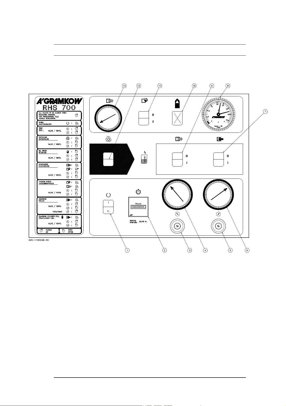
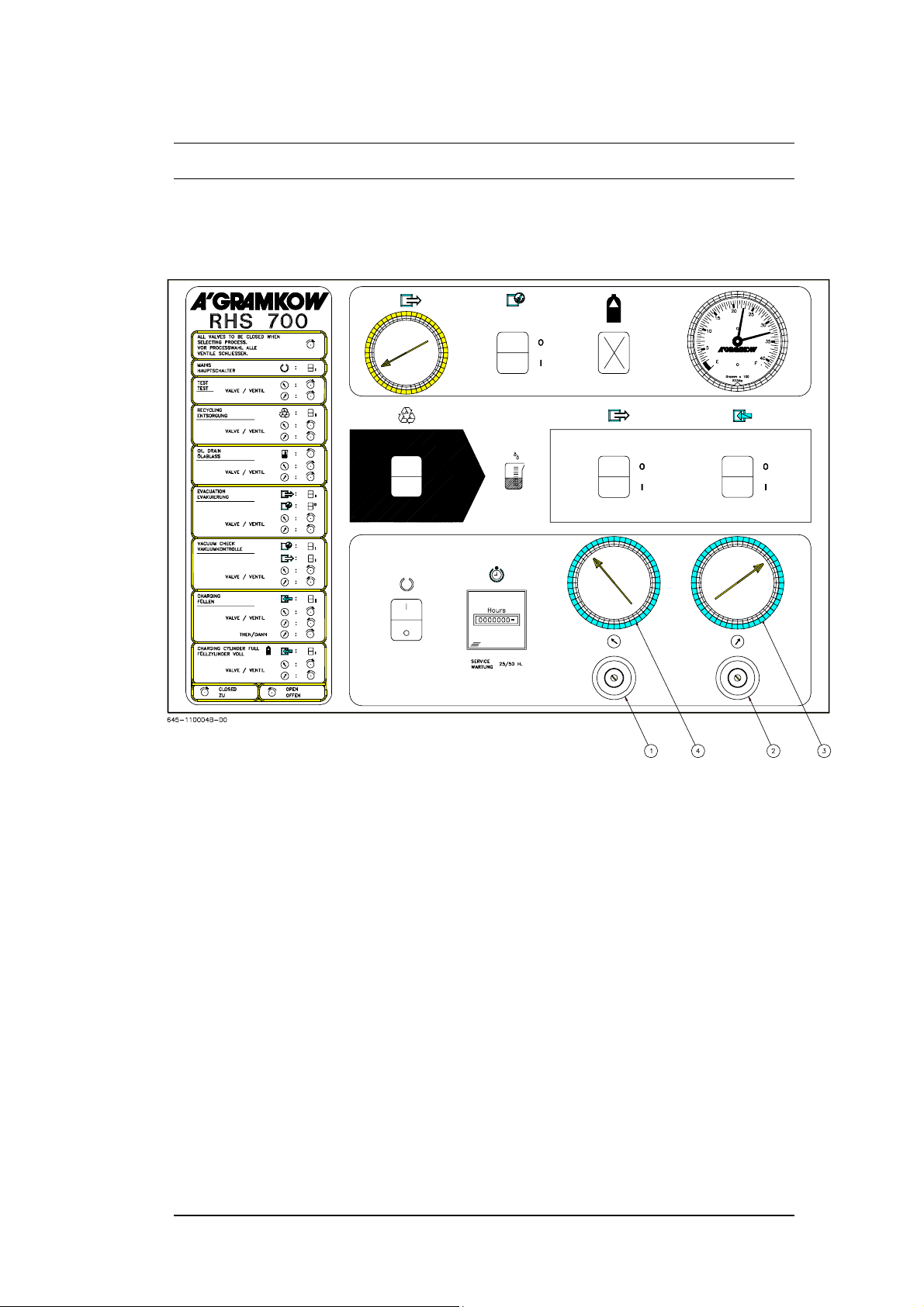
Components
1. Main switch
2. Operation time indicator
3. Low-pressure valve
4. Pressure gauge - low pressure
5. High-pressure valve
6. Pressure gauge - high pressure
7. Charging switch
8. Charging quantity indicator
9. Evacuation switch
10. Cylinder full - lamp
11. Vacuum check
12. Recovery/recycling switch
13. Vacuum gauge
C:\RHS Computer Files\Instructions\RHS\GB\645-40\0009A-01.doc 1997.03.26
RHS 700
Page 7
- 3.2 -
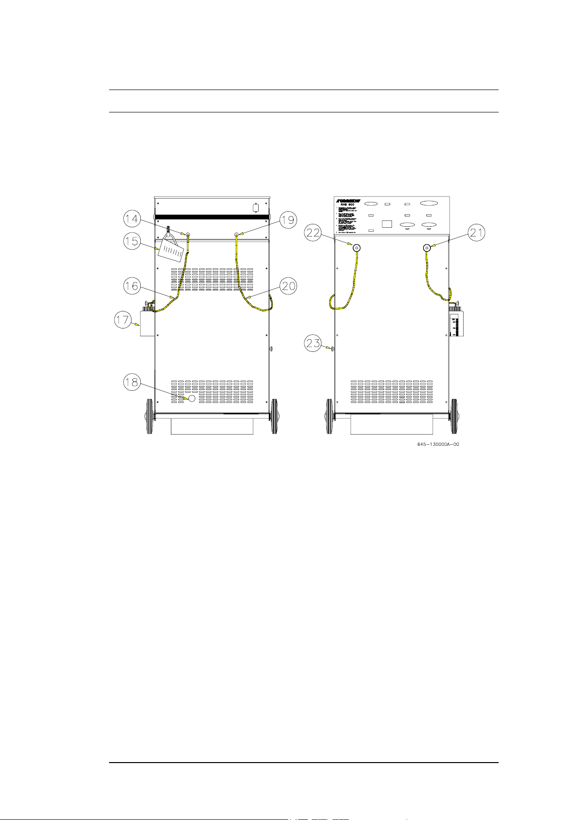
Components
14. High-pressure side
15. Oil beaker - 250 ml
16. High-pressure hose - red
17. Oil charging
18. Sightglass
19. Low-pressure side
20. Low-pressure hose - blue
21. Service coupling - high pressure
22. Service coupling - low pressure
23. Oil drain valve
C:\RHS Computer Files\Instructions\RHS\GB\645-40\0009A-01.doc 1997.03.26
RHS 700
Page 8

- 4.1 -
Before use
Check the following:
- whether the station has been damaged in transit - if so, contact supplier
immediately;
- oil level in vacuum pump: it must not be below the centre of the sight glass.
If the level is too low, see section MAINTENANCE for vacuum oil
replenishment instructions;
- whether the mains supply is as stated on the station nameplate;
- whether the refrigerant in the A/C unit is as stated on the station nameplate.
Preparation:
- Connect mains plug to mains supply.
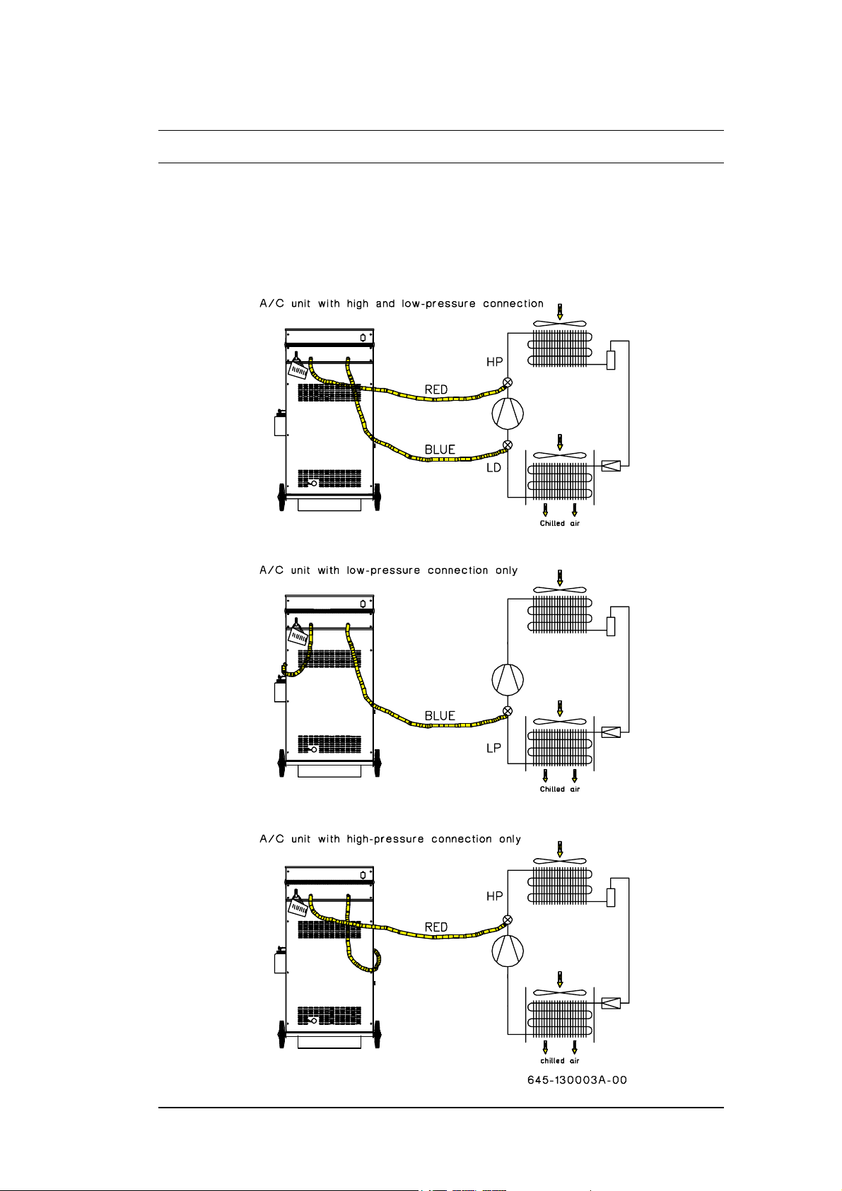
- Connect the red and blue hoses to their stubs on the rear of the station. Blue
hose to low-pressure side, red hose to high-pressure side. (See the next two
pages.)
- Make sure that the shut-off valves on hoses and pos. 5 are closed.
- Connect high and low-pressure hoses to their respective sides (using the
service couplings) on the A/C unit. (See the next two pages.)
- RHS 700 is now ready for operation.
C:\RHS Computer Files\Instructions\RHS\GB\645-40\0009A-01.doc 1997.03.26
RHS 700
Page 9
- 4.2 -
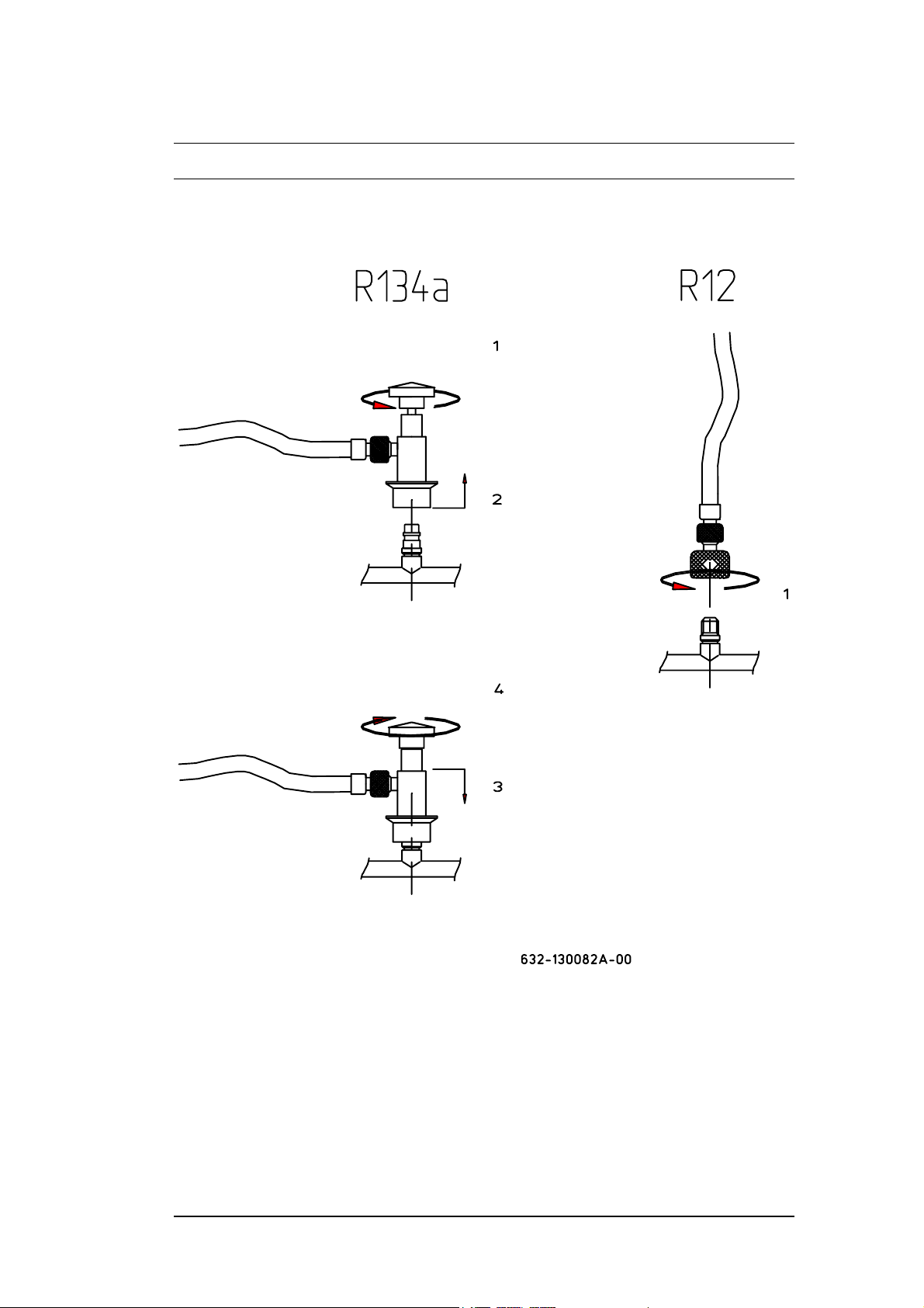
Before use
Connection of service couplings
C:\RHS Computer Files\Instructions\RHS\GB\645-40\0009A-01.doc 1997.03.26
RHS 700
Page 10
- 4.3 -
Before use
C:\RHS Computer Files\Instructions\RHS\GB\645-40\0009A-01.doc 1997.03.26
RHS 700
Page 11
- 5.1 -
Test
The test function must be performed to check the station.
1. Close both valves on the control panel (pos. 1-2).
2. Connect the high and low-pressure hoses to the A/C unit and open the service
couplings.
3. Switch on the A/C unit and read the pressures on the high and low-pressure
gauges (pos. 3/4). The correct pressures are given in the A/C unit manual.
4. Perform a condition diagnosis in accordance with the supplier’s instructions.
See appendix “Example of trouble shooting in an A/C unit”.
C:\RHS Computer Files\Instructions\RHS\GB\645-40\0009A-01.doc 1997.03.26
RHS 700
Page 12

- 6.1 -
Recovery/recycling
When an A/C unit is to be repaired or serviced, the RECOVERY/RECYCLING
process must be used in order to drain refrigerant from the A/C unit.
1. Make sure that all valves are closed, then connect high and low-pressure hoses
to the A/C unit and open the service couplings.
1. Switch on the main switch and the RECOVERY/RECYCLING
process switch
2. Open valves 1 and 2. Provided there is pressure/refrigerant in the A/C unit, it
will be automatically emptied by RHS 700. The green lamp in the RE-
COVERY/RECYCLING process switch remains on until the process is
complete.
3. When the green lamp goes out for the first time, wait 5 minutes to ensure that
the A/C unit is completely empty.
1. As soon as the charging cylinder becomes full during the RECOVERY/RE-
CYCLING process, RHS 700 stops and the yellow CYLINDER
FULL lamp lights up. The charging cylinder must then be emptied
into an A/C unit or a refrigerant cylinder before the process can be continued.
See description in the section CHARGING.
2. During the RECOVERY/RECYCLING process, oil might be drained from
the A/C unit. This oil can be tapped from oil drain valve (23) into the
accompanying measuring beaker. The A/C unit must be replenished with a
corresponding amount of oil. Follow the supplier’s instructions and use only
the specified oil type.
3. The internal cylinder is charged by connecting the service hose between
refrigerant cylinder and low-pressure stub (blue). Open the gas valve on the
refrigerant cylinder (charge only on the gas phase). Follow the instructions,
points 1, 2 and 3, until the required amount of refrigerant in the internal
cylinder has been reached. Close the gas valve on the cylinder again. When the
green RECOVERY/RECYCLING lamp goes out the process has been
completed. Close valves 1 and 2 and disconnect service hose.
Note:
Sometimes it can be an advantage to recover from the low-pressure side only, for
then no oil is drained from the A/C unit. However, if this method is used make
sure that valve 2 is kept closed.
C:\RHS Computer Files\Instructions\RHS\GB\645-40\0009A-01.doc 1997.03.26
RHS 700
Page 13

- 7.1 -
Evacuation
After servicing the A/C unit, air and/or moisture must be evacuated. Air and/or
moisture in the A/C unit will impair system operation.
1. Set the main switch on I and switch on the EVACUATION process switch
(if the pressure exceeds 0.2 barg, the evacuation process cannot be started). If
the pressure does exceed 0.2 barg, a short recovery process should be
performed.
2. Before connecting the service couplings to the A/C unit, read the vacuum
gauge. This reading is the max. level attainable.
3. Now open the service couplings on the hoses. An evacuation can be performed
if thought necessary.
4. A vacuum check must now be made. Switch on the VACUUM CHECK
process switch and at the same time watch the vacuum gauge! If the pressure
rises continuously the system either leaks or contains moisture.
5. When the evacuation process is complete, the A/C unit can be replenished with
the amount of oil which might have been taken out during the recovery
process. Open the valve, pos. 17, on the oil container on the right-hand side
and read off the required amount of oil on the scale.
Note:
If the pressure rises slightly and then restabilises, it means that the A/C unit is
adjusting itself to the ambient temperature.
C:\RHS Computer Files\Instructions\RHS\GB\645-40\0009A-01.doc 1997.03.26
RHS 700
Page 14

- 8.1 -
Charging
The required quantity of refrigerant can be seen in the vehicle manual or on the
nameplate under the vehicle bonnet.
1. Close valve 1 and open valve 2 . Then connect high and low-pressure
hoses, keeping both hose valves closed. (When charging R12 systems, do not
connect the high-pressure hose at this point).
2. Set the main switch on I and switch on the CHARGE process switch
The high-pressure hose will now contain refrigerant.
3. To ensure that the correct quantity of refrigerant is used, the red pointer on the
charging quantity indicator must now be set to determine the level at which the
black pointer indicates that the required quantity of refrigerant has been
charged (i.e. the level to which the charging cylinder is to be emptied).
Note: The charging quantity indicator will first indicate the level 2 minutes after
starting the station.
C:\RHS Computer Files\Instructions\RHS\GB\645-40\0009A-01.doc 1997.03.26
RHS 700
Page 15

- 8.2 -
Charging
4. Open the high-pressure valve on the red hose (on R12 systems simply close the
hose) and observe the charging quantity on the charging quantity indicator.
When the black pointer has reached the red pointer, the charging process must
be stopped with the process switch.
5. It is now possible to check the function of the A/C unit by closing valves 1 and
2 and opening both hose valves.
6. After completion of the A/C unit test process, close the red high-pressure hose
valve and open valves and while the A/C unit is in operation. This
empties refrigerant from the high-pressure hose and ensures the accuracy of the
refrigerant quantity charged. Now close the service valve on the blue hose. (On
R12 systems simply remove the hose.)
7. After charging, hoses will contain a small quantity of refrigerant. To recover
this refrigerant, first close hose valves and then switch over to RECOVERY
for a short time.
8. Connect the service hose between refrigerant cylinder and high-pressure stub
(red) to empty/recharge the internal cylinder. Emptying must be as described in
point 4 and recharging as described in the RECOVERY process. Open valve
and the valve on the refrigerant cylinder. The refrigerant cylinder must only be
filled to not more than 80% of its maximum volume. After emptying/recharging of the required refrigerant quantity, close the valves again. Open
valves and (low-pressure stub closed) and switch on the process
switch for RECOVERY/RECYCLING to empty the hose.
Note:
It is often a problem to charge the whole charging quantity from the high-pressure
side only. If this is the case, a two-sided charge is possible by opening valve .
C:\RHS Computer Files\Instructions\RHS\GB\645-40\0009A-01.doc 1997.03.26
RHS 700
Page 16

- 9.1 -
Maintenance
3) Suction accumulator
5) Acid filter / filter drier
6) Check valve
9) Check valve
8) Filter drier
18) Charging cylinder
M1) Compressor
M2) Condenser
M3) Vacuum pump
SP4) Pressure control
C:\RHS Computer Files\Instructions\RHS\GB\645-40\0009A-01.doc 1997.03.26
RHS 700
Page 17

- 9.2 -
Maintenance
To observe the warranty on RHS 700, all components used for maintenance must
be identical to those in the service set, see Section 9.
To ensure problem-free operation of RHS 700, the station must be maintained in
accordance with the following:
The power supply to the station must be switched off.
For each 25 operating hours:
A large amount of the moisture evacuated from the A/C unit accumulates in the
vacuum oil and therefore it can be advantageous to change the oil from time to
time. The reason moisture accumulates in the vacuum oil is that the vacuum pump
does not create the required vacuum!
Changing vacuum pump oil:
- Hold an oil beaker under the oil drain screw (pos. 34) and loosen the screw.
Allow the old oil to drain into the beaker.
- Remove the oil filling cap (pos. 32).
Retighten the oil drain screw and fill with new oil through the oil filling stub (pos.
32) until the level reaches the centre of the sight glass (pos. 33).
C:\RHS Computer Files\Instructions\RHS\GB\645-40\0009A-01.doc 1997.03.26
RHS 700
Page 18

- 9.3 -
Maintenance
The condenser cooling surface must be kept clean:
- Remove the rear panel of the station (4 screws).
- Clean the cooling surface with compressed air and perhaps a soft brush. Be
careful not to bend the fins since this would reduce the air flow and impair
condenser capacity.
- Replace rear panel.
Check the oil level in the vacuum pump:
- If the oil level is below the centre of the sight glass, replenish as follows:
- Remove cap (pos. 32) to replenish vacuum pump.
- Replenish (slowly) with vacuum oil to the correct level.
- Replace cap.
For each 75 operating hours:
Replacement of filter drier (pos. 5)
- Remove front panel (6 screws).
- Remove filter by loosening the pressure control (two 3/8” flare nuts), and
then fit the replacement filter. Always use a new filter fitted with protective
caps on the connectors.
Replacement of filter drier (pos. 8)
- Remove rear panel (6 screws).
- Remove filter by loosening the union nuts and the solenoid valve (pos. 36)
at the filter end. Loosen the nuts slowly and take out the filter.
- Fit a new filter in the station, making sure to retighten the union nuts.
- Refit pressure control and solenoid valve.
On replacing filter driers a small quantity of refrigerant escapes - therefore
follow the appropriate safety precautions.
C:\RHS Computer Files\Instructions\RHS\GB\645-40\0009A-01.doc 1997.03.26
RHS 700
Page 19

- 10.1 -
Trouble shooting
Test process
Problem Fault Remedy
Pressure gauge shows no
pressure
Pressure gauge shows
the same reading all the
time
Recovery process:
Problem Fault Remedy
Recovery process does
not start - green recovery
lamp does not light up
Recovery process does
not stop
Recovery process runs
only for a short period
1. + 2. Valve not opened
3. No refrigerant in A/C unit
1. A/C unit defective
2. A/C unit not cut in
1. RHS 700 not cut in
2. Valves not opened
3. No refrigerant in A/C unit
4. System pressure is 16 bar
5. Internal cylinder full
6. Internal component fault
1. Oil drain valve not closed
2. A/C unit leakage
3. Internal component fault
1. Valves on service couplings not opened
2. System pressure is 16 bar
3. Internal cylinder full
4. Internal component fault
1. Open high and low-pressure valves on service
couplings
2. Open valves on service couplings
3. Repair A/C unit
1. Empty A/C unit and repair
2. Cut in A/C unit
1. Cut in RHS 700
2. Open high and low-pressure valves on
service couplings
3. Repair A/C unit
4. Contact RHS 700 supplier
5. Empty cylinder
6. Contact RHS 700 supplier
1. Close valve
2. Contact RHS 700 supplier
3. Contact RHS 700 supplier
1. Open valves
2. Blow off non-condensable gases
3. Empty cylinder
4. Contact RHS 700 supplier
C:\RHS Computer Files\Instructions\RHS\GB\645-40\0009A-01.doc 1997.03.26
RHS 700
Page 20

- 10.2 -
Trouble shooting
Evacuation process:
Problem Fault Remedy
Vacuum pump does not
run
Vacuum pump runs but
does not build up enough
vacuum
Charging process:
Problem Fault Remedy
No refrigerant flow 1. High-pressure valve on service coupling
1. RHS 700 not cut in
2. Overpressure in A/C unit
3. Internal component fault
1. Service couplings not fitted correctly
2. A/C unit defective/leaking
3. Internal component fault
not opened
2. Internal component fault
3. Charging cylinder empty
4. A/C unit not evacuated
5. Heating element defective
6. Thermal protector defective
1. Cut in RHS 700
2. Cut in recovery process
3. Contact RHS 700 supplier
1. Fit service couplings correctly
2. Repair A/C unit
3. Contact RHS 700 supplier
1. Open valve
2. Contact RHS 700 supplier!
3. Connect a refrigerant cylinder and use the
recovery process
4. Recover the A/C unit again and then
evacuate it
5. Contact the RHS 700 supplier
6. Contact the RHS 700 supplier
C:\RHS Computer Files\Instructions\RHS\GB\645-40\0009A-01.doc 1997.03.26
RHS 700
Page 21

- 11.1 -
Service set no. 645-010003A (RHS 700 unit)
Quantity Description Code no.
1
1
0.25 l
0.25 l
Filter drier - short
Filter drier - long
Compressor oil - mineral
Oil for vacuum pump
069-7480069
069-7480077
290-0001250
290-0001272
C:\RHS Computer Files\Instructions\RHS\GB\645-40\0009A-01.doc 1997.03.26
RHS 700
Page 22

- 12.1 -
Accessories / Spare parts
Qty Description Code no.
Spare
parts:
1
1
1
1
1
1
1
1
1
1
1
1
1
1
1
Accessories:
1
1
1
Operating instructions
Service coupling, high pressure (R134a)
Service coupling, low pressure (R134a)
Service coupling (R12)
Service coupling (R12)
Service hose, blue (R134a) = 72"
Service hose, red (R134a) = 72"
Service hose, yellow (R134a) = 36”
Service hose, blue (R12) = 180 cm
Service hose, red (R12) = 180 cm
Service hose, yellow (R12) = 90 cm
Gasket for R134a hose - white
O-ring for R134a hose, Ø 14.5 mm
Gasket for R12 hose
Oil beaker
Oil charging (R134a)
Tracer kit R12
Tracer kit R134a
645-400008A
290-7480095
290-7480096
290-4669016
066-7390234
634-140002A
634-140001A
634-140004A
080-4665015
080-4665017
080-4665002
087-7481010
087-7481341
066-7750950
146-7489012
642-040003A
634-040007A
643-040002A
C:\RHS Computer Files\Instructions\RHS\GB\645-40\0009A-01.doc 1997.03.26
RHS 700
Page 23

- 13.1 -
Specifications
General:
Supply voltage: See nameplate
Amperage: See nameplate
Power consumption: See nameplate
Starting current: See nameplate
Weight: 95 kg
Dimensions: 1030 x 670 x 800 mm
Test function:
High-pressure gauge: 0 to 34 bar
Low-pressure gauge: -1 to 8 bar
Recovery/recycling process:
Refrigerant: See nameplate
Oil level measurement: Drain at side of station, measuring beaker
supplied
Recycling capacity: 4 kg/h (3-5 vehicles/h)
Non-condensable gases: Automatic blow-off, temperature-compensated
Suction accumulator: 2.4 litres (approx. 2 kg)
Refrigerant charge: 4.0/4.2 kg R134a/R12
Filter drier: Replaceable (every 75 hours)
Charging pressure gauge: 0-4000 g
Evacuation process:
Suction capacity: Approx. 3 m3/h
Vacuum level: < 0.5 mbar absolute
Option:
Oil charging: Oil container = 250 ml
C:\RHS Computer Files\Instructions\RHS\GB\645-40\0009A-01.doc 1997.03.26
RHS 700
Page 24

- 13.2 -
Specifications
Operating panel:
Mains switch - white: Power supply cut in
Recovery switch - green: Recovery process in function
Evacuation switch - green: Evacuation process in function
Refrigerant charging switch - green: Refrigerant charging in process
Vacuum check lamp - green: Vacuum OK
Charging cylinder lamp - yellow: Cylinder full
Service and maintenance
Filter drier 1: Replaceable, 3/8" SAE
Filter drier 2: Replaceable, 3/8” SAE (capacity 50 hours or 200
kg refrigerant)
Vacuum pump oil level: Sight glass + charging stub
Safety equipment: Mechanical safety valve on charging cylinder
Overfilling protection on charging cylinder
Suction pressure regulator on compressor
High-pressure control on compressor
Code number of RHS 700: See nameplate
C:\RHS Computer Files\Instructions\RHS\GB\645-40\0009A-01.doc 1997.03.26
RHS 700
Page 25

Wiring diagram:
- 14.1 -
Pos. no. location
(645-120000A-03)
C:\RHS Computer Files\Instructions\RHS\GB\645-40\0009A-01.doc 1997.03.26
RHS 700
Page 26

- 14.2 -
Pos. no. location
Wiring diagram
M3: Vacuum pump
Y14: Solenoid valve
Y15: Solenoid valve
Y16: Solenoid valve
EH1: Heating element
EH2: Heating element
ST1: Thermostat
ST2: Thermal protector (manual reset)
ST3: Thermostat
ST4: Thermal protector (manual reset)
M1: Compressor
M2: Fan
Y9: Solenoid valve
Y21: Solenoid valve
SL2: Level switch
Y8: Solenoid valve
SP1: Pressure control
SP2: Pressure control
SP3: Pressure control
SP4: Pressure control
SP5: Pressure control
C:\RHS Computer Files\Instructions\RHS\GB\645-40\0009A-01.doc 1997.03.26
RHS 700
Page 27

Mechanical diagram
- 14.3 -
Pos. no. location
(645-120001A-00)
C:\RHS Computer Files\Instructions\RHS\GB\645-40\0009A-01.doc 1997.03.26
RHS 700
Page 28

- 14.4 -
Pos. no. location
3) Suction accumulator
5) Acid filter / filter drier
6) Check valve
9) Check valve
8) Filter drier
18) Charging cylinder
M1) Compressor
M2) Condenser
M3) Vacuum pump
SP4) Pressure control
C:\RHS Computer Files\Instructions\RHS\GB\645-40\0009A-01.doc 1997.03.26
RHS 700
Page 29

- 15.1 -
Appendixes
Example of trouble shooting on an A/C unit:
Conditions:
1. Ambient temperature 30-35°C (86-95°F)
2. Motor speed 2,000 rpm
3. A/C unit temperature setting Maximum
Under the above conditions an intact A/C unit will show the following
pressures in the TEST process:
High pressure 15 bar
Low pressure 2 bar
Follow the TEST process as shown in section 5:
- Connect service couplings to the A/C unit.
- Close the high and low-pressure valves on RHS 700
- Open the valves on the service couplings.
- Cut in the A/C unit.
- The station will now perform a test function.
Perform a condition diagnosis in accordance with the supplier’s instructions.
- When the test is completed, cut the A/C unit off again.
C:\RHS Computer Files\Instructions\RHS\GB\645-40\0009A-01.doc 1997.03.26
RHS 700
Page 30

- 15.2 -
Appendixes
Test 1:
High pressure 8 - 9 bar
Low pressure Approx. 0.8 bar
Fault/problem Symptom Possible cause Remedy
Unsatisfactory
refrigeration output
Test 2:
High pressure Approx. 20 bar
Low pressure Approx. 2.5 bar
Fault/problem Symptom Possible cause Remedy
Unsatisfactory
refrigeration output
Virgin ventilation air
Air bubbles in sight
glass
Refrigerant over-
Leak in A/C unit
Insufficient refrigerant
in A/C unit
charged
Insufficient condenser
cooling
Fan not running
Reduced condenser
output because of oil
or dirt deposits
Insufficient oil in A/C
unit (compressor friction)
Locate leak and repair
Replenish refrigerant
Clean the condenser
Repair fan
Clean the condenser
Replenish oil
If none of the above
steps remedy the fault,
check refrigerant
quantity in A/C unit,
empty, evacuate and
recharge unit
C:\RHS Computer Files\Instructions\RHS\GB\645-40\0009A-01.doc 1997.03.26
RHS 700
Page 31

- 15.3 -
Appendixes
Test 3:
High pressure Approx. 7 - 15 bar
Low pressure Approx. 1.5 bar
Fault/problem Symptom Possible cause Remedy
A/C unit runs irregularly
Test 4:
High pressure Approx. 6 bar
Low pressure Approx. -0.3 bar
Fault/problem Symptom Possible cause Remedy
A/C unit does not cool
- or cools only slightly
Varying pressures on
high and low-pressure
sides
Hoses ahead of or after
expansion valve or
filter drier covered
with moisture or ice
Moisture in A/C unit
causes ice on expansion valve and reduces
output.
Filter drier saturated
Because of moisture in
A/C unit, expansion
valve or filter drier
blocked by ice
Empty, evacuate and
recharge A/C unit.
After recovery process
replace filter drier. If
necessary, remove and
clean expansion valve.
Replace valve or fit
new valve.
Cut out A/C unit, wait
a few minutes and
empty it. Then evacuate and recharge
A/C unit.
C:\RHS Computer Files\Instructions\RHS\GB\645-40\0009A-01.doc 1997.03.26
RHS 700
Page 32

- 15.4 -
Appendixes
Test 5:
High pressure Approx. 19 - 20 bar
Low pressure Approx. 2.5 bar
Fault/problem Symptom Possible cause Remedy
Unacceptable cooling Ice or moisture on
hoses on high and lowpressure sides of A/C
unit
Test 6:
High pressure Approx. 7 - 10 bar
Low pressure Approx. 4 - 6 bar
Fault/problem Symptom Possible cause Remedy
A/C unit does not cool Pressure on low-pres-
sure side too high or
pressure on high-pressure side too low
Expansion valve
defective or sensor
placed incorrectly
Expansion valve opens
too much
Internal compressor
leakage
Check position of
expansion valve
sensor.
Replace expansion
valve.
Repair or replace compressor
C:\RHS Computer Files\Instructions\RHS\GB\645-40\0009A-01.doc 1997.03.26
RHS 700
Page 33

- 15.5 -
Appendixes
Pressure vessel declaration
We confirm herewith that the condition of the pressure vessel in this unit
conforms to regulations laid down by the appropriate authorities:
Suction accumulator, pos. 4:
Manufacturer: Denaline S.R.L.
Via Segaluzza
11/B
Italy
Type: GRA.120.240.0
Permissible working pressure: PS = 23 bar
Permissible working temperature:
Volume: V = 2.4 litres
Filter drier, pos. 5:
Manufacturer: RTI Technologies Inc. (A’G subsidiary)
York, PA
USA
Type: 026-80069-00
Permissible working pressure: PS = 31.05 bar
Permissible working temperature:
Volume: V = 0.83 litres
-40/70°C
10/120°C
C:\RHS Computer Files\Instructions\RHS\GB\645-40\0009A-01.doc 1997.03.26
RHS 700
Page 34

- 15.6 -
Appendixes
Filter drier, pos. 8:
Manufacturer: RTI Technologies Inc. (A’G subsidiary)
York, PA
USA
Type: 026-80077-00
Permissible working pressure: PS = 31.05 bar
Permissible working temperature:
Volume: V = 0.83 litres
Charging cylinder, pos. 10
Manufacturer: A’GRAMKOW A/S
Augustenborg Landevej 19
DK-6400 Sønderborg
Denmark
Type: 645-010038A
Permissible working pressure: PS = 25 bar
Permissible working temperature:
Volume: V = 4.26 litres
10/120°C
10/70°C
C:\RHS Computer Files\Instructions\RHS\GB\645-40\0009A-01.doc 1997.03.26
RHS 700
 Loading...