

Page 1
OPERATION
&
MAINTENANCE
MANUAL
RHS2680
Refrigerant Handling System
4075 East Market Street
York, Pennsylvania 17402
Phone: 717-840-0678
Fax: 717-755-8304
E-mail: rti@rtitech.com
Manual P/N 035-80958-00
Page 2

TABLE OF CONTENTS
Startup & Safe Operation ................... 1
Introduction to the RHS2680 ................. 2
Control Panel ............................. 3
Keypad Functions ......................... 4
Start-Up ................................. 5
Recover (Recycle) ......................... 6
Purge Air - Drain Oil ....................... 6
Vacuum ................................. 7
Charge .................................. 7
Maintenance ............................. 8
Parts Lists ............................... 9
FSC Adapter for DOT ......................11
CONGRATULATIONS
You have purchased one of the finest Recovery, Recycling,
and Charging Machines available!
Fill out and return the Warranty Card within 90 days to
activate the warranty and free lifetime technical support.
TECHNICAL SUPPORT
800-468-2321 (Ext. 259)
tech@rtitech.com
Page 3

STARTUP & SAFE OPERATION
9 Do not use a damaged unit. Check for shipping damage and place a claim with carrier if damage
is discovered.
9 Return the Warranty Card to activate technical support service and warranty coverage.
9 The RHS2680 should not be operated or serviced by any person who has not read all the
contents of this manual.
9 This manual describes normal operation and maintenance for the RHS2680. Failure to read and
comply with these instructions or any one of the limitations noted herein can result in serious
injury and/or property damage. The instructions should not be interpreted to anticipate every
possible contingency.
9 It is the responsibility of the owner/user to operate the RHS2680 in accordance with all laws and
specifications which may apply.
9 Recover (recycle) and charge only the refrigerants for which the RHS2680 is configured.
9 Avoid breathing refrigerant or lubricant vapor. Exposure may irritate eyes, nose and throat.
Ventilate work area if accidental system discharge occurs.
9 Wear safety glasses and protective gloves. Refrigerant has a very low boiling point and can
cause frostbite.
9 Follow the RHS2680 operating procedures sequentially to avoid prematurely disconnecting
hoses or opening valves which may release refrigerant to the atmosphere.
9 Do not expose the RHS2680 to moisture or operate in wet areas.
9 Use the RHS2680 in locations with ventilation that provides at least four air changes per hour.
9 Hoses must have shutoff devices within 12 inches of the connection point to the A/C to minimize
the introduction of air into the RHS2680 and the release of refrigerant when being disconnected.
9 Avoid using an extension cord with the RHS2680. If necessary use a good condition, three wire
grounded, #14 AWG or larger extension cord of the shortest possible length.
9 Disconnect power before performing any maintenance or service on the RHS2680.
9 Do not connect the red or blue hoses to the liquid port of a cylinder of refrigerant to fill the charge
cylinder. Doing so may cause the compressor to fail and void the warranty.
9 Do not connect the RHS2680 to the liquid side of any A/C with a capacity greater than 4 lbs.
Refrigerant in A/C Systems having larger capacities must be recovered from the vapor side only.
Special Considerations with R134a
R134a has been shown to be nonflammable at ambient temperature and atmospheric pressure.
However, tests under controlled conditions have indicated that at pressures above atmospheric and
with air concentrations greater than 60 percent by volume, R134a can form combustible mixtures.
While it is recognized that an ignition source is also required for combustion to occur, the presence
of combustible mixtures is a potentially dangerous situation and should be avoided.
Under no circumstances should any equipment be pressure tested or leak tested with air and R134a
mixtures. Do not use compressed air for leak detection in R134a systems.
Page 1
Page 4
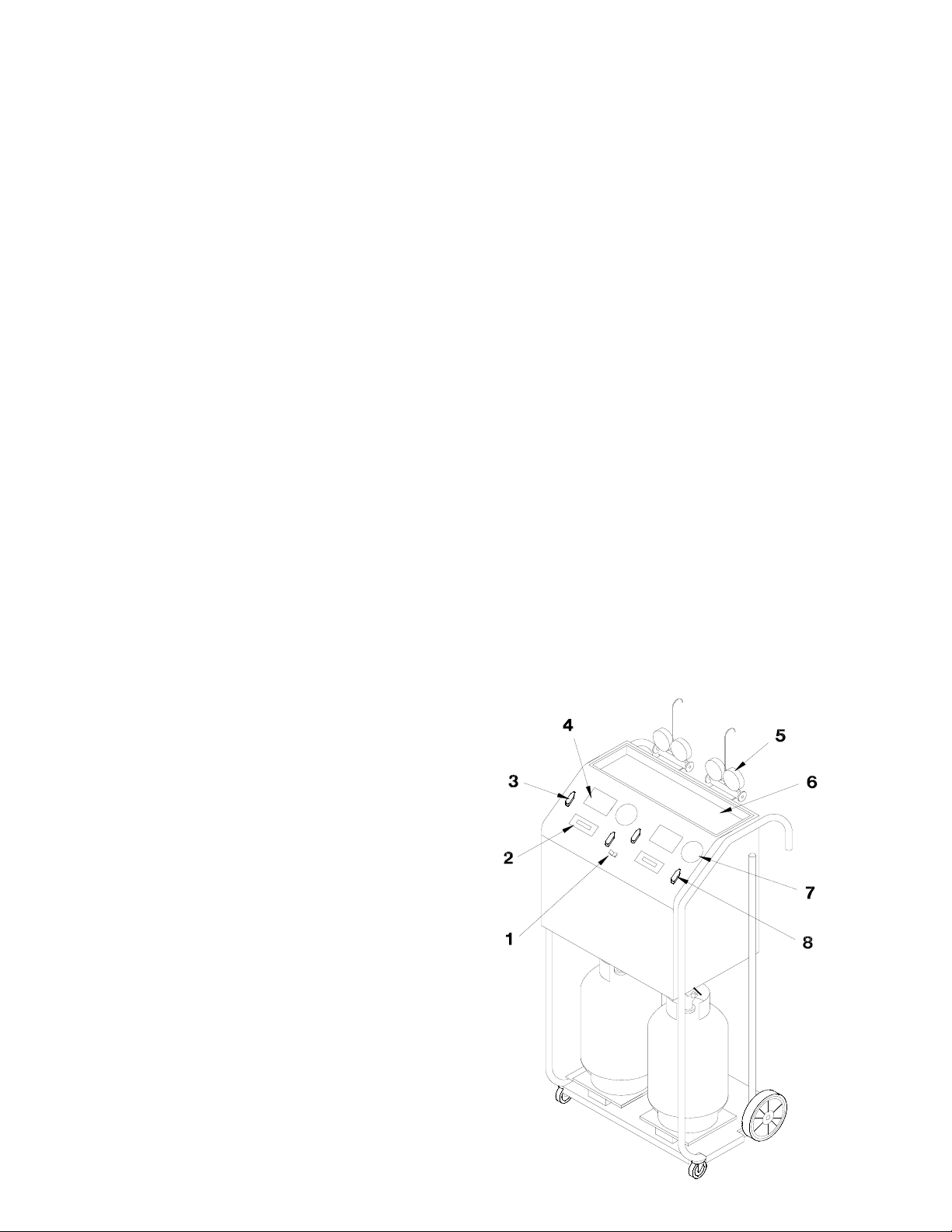
INTRODUCTION TO THE RHS2680
The RHS2680 is a complete refrigerant management center featuring state-of-the-art electronic
control with digital weight scale measuring of refrigerant. Operation of the RHS2680 is intuitive and
very easy to master.
Following is an overview of the operation and features of the RHS2680:
RECOVER (RECYCLE)
Refrigerant is recovered from the A/C, impurities (particulates, oil, moisture and air) are removed
and the refrigerant is stored in the internal cylinder. The recovery process stops when the
RHS2680 senses an 8 InHg vacuum at the A/C. Wait for at least two minutes and watch the
pressure gauges to determine if there is an increasing pressure. If pressure in the A/C rises
during this time period due to vaporization of residual liquid refrigerant, the RHS2680 will restart
to recover this refrigerant. When the RHS2680 stays off continually for at least two minutes, the
recovery procedure is complete.
VACUUM
A deep vacuum should be drawn on the A/C to remove air, moisture and refrigerant dissolved
in the oil. A deep vacuum is especially important if the A/C was opened for replacement of
components.
PURGE AIR - DRAIN OIL
Excess air and recovered oil must be removed from the RHS2680 after all refrigerant has been
recovered from the A/C. Temperature and pressure readings are examined and air is released
using the purge valve. Oil is drained into the oil drain cup for measuring to determine the need
to replenish the A/C.
CHARGE
Refrigerant is charged into the A/C by weight. The amount to be charged is entered and the
RHS2680 automatically charges the refrigerant into the A/C.
1 R12/R134a Selector Switch
2 Keypad
3 Function Valve
4 Purge Chart
5 Gauge Manifold
6 Tool Tray
7 Purge Gauge
8 Purge Valve
Page 2
Page 5

0
F
32
34
36
38
40
42
44
46
48
50
52
PSIG
44
46
48
50
52
54
57
59
61
64
66
CONTROL PANEL
PURGE CHART - R12
0
F
54
56
58
60
62
64
66
68
70
72
74
PSIG
69
72
74
77
80
83
85
88
92
95
98
0
F
76
78
80
82
84
86
88
90
92
94
96
PSIG
102
105
108
112
115
118
123
127
130
135
138
0
F
32
34
36
38
40
42
44
46
48
50
52
0
F
98
100
102
104
106
108
110
112
114
116
118
PSIG
42
44
46
49
51
54
56
59
61
64
67
PSIG
143
147
150
155
160
165
168
173
178
183
188
PURGE CHART - R134a
0
F
54
56
58
60
62
64
66
68
70
72
74
PSIG
70
72
76
78
82
85
88
92
95
97
104
0
76
78
80
82
84
86
88
90
92
94
96
F
PSIG
107
110
114
118
123
127
130
135
140
145
148
0
F
98
100
102
104
106
108
110
112
114
116
118
PSIG
153
157
163
167
173
180
185
190
195
200
207
Page 3
Page 6

KEYPAD FUNCTIONS
Scroll Key Press to scroll through function
options or to increase numeric
values shown on the display.
Cursor Key Press to move flashing cursor on
the display prior to numeric entries.
Go Key Press to confirm data entry and
continue.
Stop Key Press to halt program sequence.
Units Key Press to change unit of measure for
weight displays.
- CAUTION -
Always use fingers to operate keypad.
Use of sharp objects will cause damage.
Page 4
Page 7

START-UP
1. Turn Function Valves and Purge Valves on RHS2680
to OFF. Connect yellow hoses of gauge manifolds to
ports on rear of RHS2680. Close high and low valves
on gauge manifolds.
2. Connect red and blue hoses from the gauge manifold,
for the refrigerant to be processed, to A/C system and
open hose valves.
3. Connect power cord of RHS2680 to properly grounded
power source. Avoid using an extension cord. If
necessary use a good condition, three wire grounded,
#14 AWG or larger extension cord of the shortest
possible length.
4. Select refrigerant to be processed using the
R12/R134a Selector Switch. The corresponding display
and keypad will be energized.
5. RTI TECHNOLOGIES and 680/2860 SERIES will
display for ten seconds.
6. The display will show the weight of refrigerant in the
RHS2680 cylinder and prompt RECYCLE?
7. Press [5] key to begin a recycle procedure (Page 6) or
press [>] key to go to next screen (See next step).
8. The display will show the weight of refrigerant in the
charge cylinder and prompt VACUUM?
W W W W CAUTION W W W W
Make sure the A/C pressures are at zero or below. If
the gauges indicate positive pressure, refrigerant will
be vented to the atmosphere. Perform a recover
procedure before starting a vacuum procedure.
9. Press [
press [
5] key to begin a vacuum procedure (Page 7) or
>] key to go to next screen (See next step).
10. The display will show the weight of refrigerant in the
charge cylinder and prompt CHARGE?
11. Press [5] key to begin a charge procedure (Page 7) or
press [>] key to return to Step 6 above.
Page 5
Page 8

RECOVER (RECYCLE)
1. Turn Function Valve on RHS2680 to RECOVER.
2. Open high and low valves on gauge manifold.
3. The display will show the weight of refrigerant in the
RHS2680 cylinder and indicate the unit is recycling.
4. When the A/C system pressure is in a vacuum the
display will show RECYCLE COMPLETE CHECK
PRESSURES. Wait two minutes to see if the pressure
in the A/C increases (due to liquid refrigerant
vaporizing). The RHS2680 will automatically begin
recycling again if the pressure rises above zero.
5. Press the stop key and close the high and low valves on
the gauge manifold.
6. Turn Function Valve on RHS2680 to OFF.
Note:
The display will show CYLINDER FULL GO TO CHARGE
if the RHS2680 cylinder fills to capacity. Press the STOP
key and perform a charge procedure to transfer refrigerant
to another A/C system or an external storage cylinder.
PURGE AIR - DRAIN OIL
IMPORTANT: Oil must be drained and Air purged after each recover (recycle) procedure.
Failure to do so will cause excess air to be introduced into the A/C during charge and the
RHS2680 will fill with air causing a high-pressure shutdown.
1. The oil drain valve is accessible from the rear of the RHS2680, located under the main
enclosure. Slowly open the valve and drain any oil into the measuring cup to determine how
much oil (if any) should be added to the A/C.
2. Leave the oil drain valve open.
3. Measure the room temperature.
4. Find the corresponding pressure for this temperature on the purge chart printed on the RHS2680
top panel.
5. Compare this pressure from the chart with that indicated on the Purge Gauge. If the gauge
shows a higher pressure, slowly open the Purge Valve a small amount until the pressure drops
to approximately the pressure shown in the chart.
6. Turn the purge valve to OFF.
7. Close the oil drain valve.
Page 6
Page 9

VACUUM
1. MAKE SURE THE GAUGE MANIFOLD PRESSURES
ARE ZERO OR LESS. If not, a recover procedure must
be performed before starting the vacuum procedure.
2. Turn Function Valve on RHS2680 to VACUUM.
3. Open high and low valves on gauge manifold.
4. The display will show the weight of refrigerant in the
RHS2680 cylinder and indicate the unit is vacuuming.
5. At the end of the desired vacuum time, press the stop
key and close the high and low valves on the gauge
manifold.
6. Turn Function Valve on RHS2680 to OFF.
CHARGE
1. Open either the low or high valve on gauge manifold
and corresponding hose valve according to the A/C
manufacturer’s recommendation for charging the system.
2. Enter weight of charge desired using the keypad. Press
the [>] key to increase numeric value shown on display
and press [<] key to move flashing cursor to next
position. Press [5] key to start charging.
3. Turn Function Valve on RHS2680 to CHARGE.
4. Do not run the A/C during the charge procedure.
5. The display will show the amount of refrigerant being
charged into the A/C.
6. The display will show CHARGE COMPLETE
EVACUATE HOSES when the correct amount of
refrigerant has been charged.
7. Press the stop key and close the hose valve.
8. Turn function valve to OFF.
9. Evacuate the hose by running a recycle procedure.
Note:
The display will show LOW LEVEL GO TO RECYCLE if the
RHS2680 cylinder does not contain enough refrigerant to
complete the charge weight entered. Press the STOP key
and perform a recycle procedure to transfer refrigerant into
the RHS2680 cylinder.
Page 7
Page 10

MAINTENANCE
The RHS2680 will provide many years of reliable service if properly maintained. Following is a
checklist of items which will ensure the RHS2680 performs at peak efficiency and presents an image
to your customers that your shop performs high tech A/C service.
1. Use tool tray for storage of tools and accessory adapters.
2. Store gauge manifolds and hoses properly when not in use. Avoid hanging hoses over the
top of the unit.
3. Keep the exterior surfaces clean. Use a mild all purpose cleaner to wipe oil and dirt off the
cabinet.
4. Do not allow the unit to sit outside in direct sunlight or inclement weather. Excessive
exposure to sun light and moisture may cause damage and will void the warranty.
5. The RHS2680 is not intended to be used for mobile A/C service where the unit is
transported to customer sites. Excessive vibration will shorten component life.
6. Be gentle when moving the RHS2680 around the shop. Tip the unit and ease the front
casters over any obstacles such as door jams, air hoses and floor irregularities.
7. Periodically remove the front cover and check for refrigerant leaks inside the RHS2680
using a leak detector. A small leak detected early will prevent future undetected loss of
refrigerant.
8. Use regulated, clean shop air to remove debris from the fins of the condenser coil. Be
careful and do not disturb any internal components.
9. During filter changes every 25 hours, it is IMPERATIVE for the longevity of the
RHS2680, that two ounces of compressor Poly Ester Oil (POE) RTI P/N 011-80021-00
be added to the compressor to replenish oil lost during the previous 25 hours of
operation. Not adding oil at recommended intervals or using oil other than RTI P/N
011-80021-00 will void the warranty.
10. Change filters after every 25 hours of recovery operation. Filters must be changed at least
once per year for efficient recycling of refrigerant.
FILTER CHANGE & ADDITION OF COMPRESSOR OIL
Filters (see next page for RTI part numbers) must be changed and oil must be added to the
compressor after every 25 hours of recycling refrigerant. The display will show “CHANGE FILTERS
+2OZ - COMP OIL”. This reminder will be displayed whenever the RHS2680 is turned on or a new
procedure is started.
Disconnect power and remove tool tray from top of RHS2680. Use end wrench to loosen and tighten
copper tube fittings on filters. The foam insulation on the smaller outlet filter must be removed from
the old filter and reinstalled on the new one. Check for leaks after replacing filters.
Locate compressor oil fill port (tag attached to port). Remove plug from the fill tube using two end
wrenches. Fill the syringe (supplied with RHS2680) with two ounces of oil (RTI P/N 011-80021-00).
Apply power and place RHS2680 in Vacuum Mode. Insert tip of syringe in fill port and inject the two
ounces of oil. The vacuum will pull the oil into the compressor. Press Stop. Disconnect power and
install plug on fill tube using two end wrenches.
Apply power. The display will show “CHANGE FILTERS +2OZ - COMP OIL”. While this message
is displayed, press and hold the [<] key and the [>] key for two seconds to reset.
Page 8
Page 11

PARTS LIST
P/N DESCRIPTION P/N DESCRIPTION
1 360-81574-00 Expansion Valve Assy 8 026-80069-00 Combo Filter 3/8 Flare
(Short)
2 024-80037-00 Contactor ½ HP
120V 3NC/1NC
3 026-80077-00 Combo Filter 3/8
Flare (Long)
4 360-81307-00 High Pressure Switch
261 psig
5 360-81670-01 Compressor Assy
2680 (120V)
6 360-81547-01 Assy Heater Belt 13 360-80851-00 Oil Drain Assy
7 031-80000-00 Load Cell 35Kg 14 360-81428-00 Internal Cylinder (DOT)
9 025-80304-00 Solenoid Valve
120V
10 360-81309-00 Low Pressure Switch
3psig - 8InHg
11 360-80280-00 Condenser Assy
12 360-80416-00 Fan Assy w/Pins
120V
Page 9
Page 12

PARTS LIST
P/N DESCRIPTION
1 360-81739-00 Main Ball Valve Assy (2680)
2 024-80070-00 Keypad Overlay 680/550/2860
3 026-80071-02 Purge Gauge Assy 0-500 psig
4 360-81576-00 Purge Ball Valve Assy (2860)
5 024-80072-00 Circuit Board 680/550/2860
6 024-80066-00 Switch Rocker SPDT (on-on) Visi-Red
Page 10
Page 13

Page 11
 Loading...