

Page 1
OPERATION MANUAL
NTF-15
Nitrogen Tire Filling
Valve Stem Caps (Qty=200)
Order P/N 436075
035-81235-00 (Rev B)
RTI Technologies, Inc
10 Innovation Drive
York, PA 17402
800-468-2321
www.rtitech.com
Page 2

TABLE OF CONTENTS
Pictograms .................................. 1
Health, Safety and Environmental Aspects .......... 1
Description of the NTF-15 Membrane .............. 2
Process Parameters ........................... 3
Unpack & Check Equipment ..................... 3
Safety Precautions ............................ 4
Operation ................................... 4
Testing Nitrogen Purity ......................... 6
Maintenance ................................. 7
Parts Identification ............................. 8
Flow Diagram ................................ 9
Normal Operation – Loss of Pressure
Nitrogen is generated by the NitroPro and retained in the storage
tank. Nitrogen generation stops when this tank fills to the specified
design pressure.
The pressure in the NitroPro storage tank may drop after extended
non-use (over night for example). This is normal, and is similar to
air compressors that will periodically cycle on to replenish pressure
lost in the air storage tank and attached delivery system.
Permeation through service hoses, fill nozzles, valves and other
components directly associated with nitrogen generation is to be
expected, and does not impact normal operation.
It may take a few minutes to replenish the pressure in the storage
tank to maximum next time the NitroPro is used. This is normal.
Page 3
PICTOGRAMS
In this manual the following pictograms are used:
Warning
A warning shows a hazard that can cause death or serious injury. Follow the instructions.
Caution
A caution shows a danger that can cause damage to the equipment. Follow the instructions.
Warning
Risk of death due to suffocation.
Risk of fire
Oxygen-enriched air leads to an increased risk of fire in the event of contact with flammable products.
High pressure risk
Follow the instructions with respect to compressed gasses.
Instructions with respect to the environment.
HEALTH, SAFETY AND ENVIRONMENTAL ASPECTS
General
Correct use of the NTF-15 nitrogen generator is important for your personal safety and for trouble-free functioning.
Incorrect use can cause damage to the NTF-15 or can lead to incorrect gas supply to the customer’s process.
Warning
Read this manual before you start operating the NTF-15. Prevent accidents and damage.
Contact RTI if you detect a problem that you cannot solve with this manual.
Compressed air
Warning
Ensure that the feed air pressure can not exceed 190 psig.
Page 1 of 9
Page 4
Nitrogen and Oxygen
The NTF-15 generates nitrogen as a product. Oxygen enriched air is released as waste.
Warning
Nitrogen can cause suffocation! Oxygen-enriched air leads to increased risk of fire in the event
of contact with flammable products. Make sure that there is adequate ventilation at all times!
Do not install the NTF-15 in an area where explosive substances may be present.
DESCRIPTION OF THE NTF-15 MEMBRANE
General
The NTF-15 separates compressed air into nitrogen and an oxygen enriched air stream. The separation system is based
on membrane technology. The compressed air comes from a central system or from a dedicated compressor.
The nitrogen produced is stored in the nitrogen storage vessel. The NTF-15 then switches on and off, depending on the
nitrogen demand.
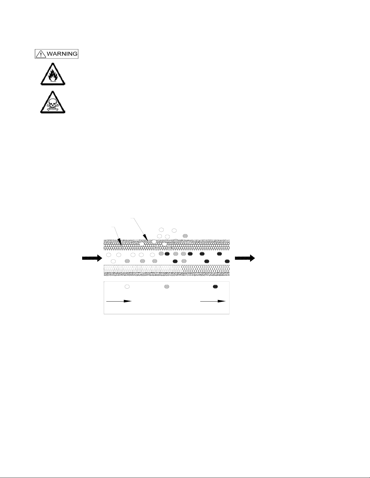
Separation Principle
Separation Layer
Support Layer
B
Pressurized
Air Nitrogen
A C
HO,H
22
FS
A Pressurized air inlet F Fast
B Hollow fibre membrane S Slow
C Nitrogen outlet
Ambient air contains nitrogen (78.1%), oxygen (20.9%), argon (1%), carbon dioxide, water vapor and traces of other inert
gasses. Pressurized air (A) is fed through the hollow fiber membrane (B). The various air components diffuse through the
wall of the membrane.
O
2
N
2
The diffusion rate differs for the various gasses:
Oxygen and water vapor have a high diffusion rate and permeate rapidly through the membrane wall.
Nitrogen has a low diffusion rate and permeates slowly through the membrane wall.
At the exit of the membrane (C), pressurized nitrogen is released.
Page 2 of 9
Page 5

PROCESS PARAMETERS
The nitrogen production depends on these parameters:
Flow rate The lower the flow rate of compressed air through the hollow fiber membrane, the more oxygen
can permeate through the membrane wall. As a result, the nitrogen produced at the outlet will
have a higher purity. Nitrogen purity can be adjusted with the flow control valve.
Temperature The NTF-15 operates at a temperature between 40-110
increases, the pressurized air consumption will also increase. Do not place the system in a room
where the temperature may rise unnecessarily high.
Allow enough piping between the compressor exit and the NTF-15 inlet so that the hot
compressed gas has time to cool within the specifications listed in this manual.
Membrane pressure A higher membrane pressure will increase the capacity (i.e. nitrogen output) of the NTF-15.
Pressure also enables operation of the pneumatic pressure switch.
External pressure There must be atmospheric pressure at the outlet. The capacity and the purity of the nitrogen
gas decreases strongly if the vent pressure exceeds the atmospheric pressure.
Clean Shop Air – Proper Flow & Pressure
Many shop air supplies have an oiler installed to provide lubrication for air
tools. The life of the filters in the NitroPro will be increased if the shop air
supply is free from moisture and oil.
0
F (70-800F optimally). If the temperature
Recommendation - install a separate air line without an oiler to connect to
the NitroPro. If this is not practical, consider installing a separate pre-filter
before connecting the NitroPro to limit potential contamination to the
NitroPro filters.
Also, ensure the shop air supply meets the pressure and flow ratings
stated in the NitroPro Operation Manual for maximum nitrogen generation.
UNPACK & CHECK EQUIPMENT
Ensure that all components were delivered.
Ensure that the compressed air source meets specification:
Oil content of the compressed air is below 0.01mg/m
Ensure that the compressed air pressure and quality is always as prescribed.
Ensure that the air capacity is sufficient.
3
.
Page 3 of 9
Page 6

SAFETY PRECAUTIONS
Warning
Ensure there is sufficient ventilation.
Only feed the NTF-15 with air.
Keep the air feed to the NTF-15 clean and free of vapors of organic solvents and other contaminants.
Do not place the NTF-15 in a room where organic solvent vapors may be present.
Keep the ambient temperature between 40 and 110 °F. Do not connect hot compressed air directly from
a compressor to the inlet of the NTF-15.
Regular maintenance should be performed on the NTF-15 to ensure proper and safe operation.
Ensure that instructions concerning health and safety are compliant with local regulations.
Environmental Aspects
The use and maintenance of the NTF-15 do not include environmental dangers. Most parts are made of metal
and can be disposed of in a manner consistent with local regulations.
Make sure that instructions concerning health, safety and environment are compliant with all local regulations.
OPERATION
Tires which have been in service may contain foreign substances such as leak
sealers. It is important that these substances are not pulled into the NitroPro unit
during the vacuum procedure, resulting in possible performance issues and costly
repairs not covered by RTI’s warranty.
When servicing a vehicle, first check the valve stems and valve stem caps for any
type of fluid or foreign substance. Install deflators and allow all four tires to deflate
to zero pressure. Then check the deflators for any indication of fluids or foreign
substances.
Do not use the NitroPro vacuum procedure on any tire where evidence of fluids or
foreign substances are detected on the valve stems, valve stem caps or deflators.
Instead, follow a four step “deflate-inflate-deflate-inflate” process to achieve
desired nitrogen purity.
Foreign Substances in Tires
Page 4 of 9
Page 7

Vacuum Tire
1. Install deflators and check for foreign substances as explained on the preceeding page.
2. Connect shop air to the air inlet port on the rear of the NTF-15. Verify pressure indicated on panel mounted Air
Pressure gauge is between 120 - 150 PSI.
3. Turn both panel valves to VACUUM TIRE.
4. Remove deflator and connect Pressure Gauge (on the end of the NTF-15 coiled green hose) to the tire valve stem.
Squeeze handle to vacuum the tire. Periodically release the handle to observe the vacuum level. Do not vacuum
to a level where the tire starts to deform.
If your application requires an inlet pressure of 100 - 119 PSI, an
adjustment to the automatic pressure switch may be required.
Contact RTI Technical Support at 800-468-2321 for further details
Fill Tire
1. Connect shop air to the air inlet port on the rear of the NTF-15. Verify pressure indicated on panel mounted Air
Pressure gauge is between 120 - 150 PSI. Verify Nitrogen pressure indicated on the panel mounted N
gauge is adequate for service.
2. Turn both panel valves to FILL TIRE.
Pressure
2
3. Connect Pressure Gauge (on the end of the NTF-15 coiled green hose) to the tire valve stem. Squeeze handle to fill
tire. Periodically release the handle to observe the pressure level. Stop when the pressure reaches the tire
manufacturer’s recommended inflation pressure. Do not over inflate.
4. Install an RTI N
Cap (Package of 200 - Part Number 436075).
2
Note: While not using the NTF-15 to fill or vacuum tires, generate Nitrogen and increase the Nitrogen
pressure in the internal storage tank by turning both panel valves to STANDBY.
Note: While using the NTF-15, the automatic drain feature of the filters may activate to remove excess
water and oil. This is normal with the standard operation of the unit.
Page 5 of 9
Page 8

TESTING NITROGEN PURITY
The NitroPro Purity Tester can be used to determine the percentage of nitrogen produced by the NTF-15 by connecting
to the Test Port. It can also be used to determine the percentage of nitrogen in the air in the tires after performing a
service.
Refer to the Operation Manual for the NitroPro Purity Tester (035-81169-00) for further details.
Testing Nitrogen Purity
The tester continually releases a small amount of nitrogen from
the tire when it is connected to the valve stem and while it
displays the reading. This is normal.
IMPORTANT - this release of nitrogen will decrease the
pressure in the tire. Therefore, it is important that when testing
is completed that you check the tire pressure and refill as
required to the tire manufacturer’s specification.
Helpful Hint – Purity Testing
When using the Purity Tester to measure nitrogen purity in a tire,
you can minimize the pressure loss, and corresponding refill
requirements, by removing the Tester from the valve stem after
a sample has been obtained.
You will notice that the reading continues to climb after the
Tester has been removed; this a function of the response time
of the internal sensor. Once the rate of change in the reading
begins to slow down or stabilize, reapply the Tester to the valve
stem to obtain another sample.
This method is particularly effective at the beginning of the test
procedure, when large changes in nitrogen purity readings
quickly occur.
Even if you follow this method, you should ALWAYS RECHECK
THE TIRE PRESSURE when purity testing is complete and
replenish nitrogen as necessary.
Page 6 of 9
Page 9

MAINTENANCE
Part Action Frequency
Filter Replace filter element. One time per year, or when indicator
on the filter head reaches the end of
the indicator bar.
Automatic drain Clean automatic drain. When required
Replace Filter Element
Turn off the air supply.
Let the system depressurize until the pressure gauge reads 0 psi.
Unscrew the bleed screw (F) slowly to ensure that the filter is depressurized.
Turn the filter bowl (E) counter- clockwise and pull the bowl from the filter
housing (A).
Unscrew the blue knob (D).
Remove the old filter element (C).
Clean the sieve (B) and the filter house, if necessary.
Install a new filter element (C).
Assemble the parts in the reverse order.
Note: A periodic check of the automatic drains is neccesary to ensure the
membrane life. To verify float is functioning correctly, open the filter bowl
by turning one quarter turn counter-clockwise. Inspect for water or oil,
an inactive float will be submerged, an active float will not. If float is
found to be inactive, follow cleaning procedure below or if necesary
replace with part number 026-80386-00.
Clean Automatic Drain
Open the filter by turning the bowl one quarter turn counter-clockwise.
Unscrew the nut (F).
Remove the drain unit (B-E) from the filter bowl (A).
Remove the O-ring (E).
Carefully pull the floating house (B) from the seat (D). Do not bend the
needle (C).
Clean the parts with soap and water. Make sure that the needle bore is open
and clean.
Assemble the parts in the opposite direction. Make sure that the parts are dry
before reassembly.
Automatic Pressure Switch Setting
The automatic pressure switch is factory pre-set to shut off shop air consumption at 120 psi. This switch will then
automatically reset when the N
If your application requires an inlet pressure of 100 - 119 psi, an adjustment to the automatic pressure switch is possible.
Please contact RTI Technical Support at 800-468-2321 for further details.
Pressure inside the tank drops by approximately 25 psi.
2
Page 7 of 9
Page 10

PARTS IDENTIFICATION
AIR PRESSURE
1
PURITYN
PRESSURE
N
2
2
TEST PORT
2
NTF-15
VACUUM
VACUUM
FILL TIRE
STANDBY
TIRE
STANDBY
FILL TIRE
TIRE
3
4
CONNECTED TO
BALL VALVE
Part Number Description
1 026-80379-00 2 in Gauge 0-160 psig/bar 1/4MPT
2 023-80364-00 FTG Test Port 1/4 MPT X valve stem
3 022-80028-00 3-way ball valve 1/4 FPT (BHD)
4 026-80330-00 pneumatic vacuum pump
5 022-80005-00 relief valve 300 psi
5
6
7
6 026-80394-00 nitrogen membrane (2.1 CFM)
7 022-80141-00 pneumatic pilot valve
8 022-80131-00 adjustable pneumatic pressure switch
8
9
9 022-80128-00 check valve 3/8 FPT
10 026-80377-00 15 gal vertical tank
10
11 022-80129-00 needle valve 3/8 FPT
12
12 026-80381-00 water filter with auto drain
13 026-80386-00 auto drain float
14 026-80382-00 oil filter with auto drain
15 026-80383-00 moisture filter
560-80375-00
11
16 028-80362-00 coiled green hose
17 023-80372-00 air chuck with pressure gauge
Filter Replacement Kit
355-80025-00 (Includes Filters for Item 12, 14 and 15)
N
Caps for Valve Stem (Qty=200)
2
P/N: 436075
13
14
15
Page 8 of 9
16
17
Page 11

FLOW DIAGRAM
Page 9 of 9
 Loading...