

Page 1
OPERATION MANUAL
MCX-2S
Multiple Coolant Exchanger
S
Y
S
T
E
M
P
R
E
S
S
U
R
E
S
Y
S
T
E
M
V
A
C
U
U
M
L
O
W
E
R
&
R
O
A
V
D
E
I
R
A
F
T
L
O
O
R
L
O
W
E
&
R
O
R
A
V
D
E
R
I
A
F
T
L
O
O
T
R
E
W
E
S
M
T
P
T
Y
W
A
S
T
E
T
A
N
K
F
I
L
L
&
O
V
E
W
O
F
F
E
X
F
C
I
L
H
L
A
R
N
A
G
D
E
I
A
C
T
O
O
O
R
L
&
A
N
O
T
V
E
O
R
R
F
L
O
W
E
X
C
H
A
N
G
E
C
O
O
F
O
F
L
A
N
T
R
A
D
I
A
E
R
T
M
F
O
L
P
R
O
T
W
Y
W
A
S
T
E
T
A
N
K
O
F
F
RTI Technologies, Inc.
4075 East Market St.
York, PA 17402 USA
800-468-2321 Where Else?
www.rtitech.com
Manual Number 035-80863-00 (Rev G)
TM
Page 2

TABLE OF CONTENTS
Component Description ....................... 2
Safety Precautions ........................... 3
Operation of Valves .......................... 3
Set-up..................................... 4
Relieving Radiator Pressure.................... 5
Lowering Coolant Level ....................... 6
Connecting to the Coolant System ............... 7
Special Hookups............................. 8
Coolant Replacement......................... 9
Test Coolant System for Leaks ................. 11
Completing the Job........................... 12
Changing Coolant Type ....................... 14
Emptying the Waste Tank ..................... 16
Replacement Parts........................... 17
Waste Pump Impeller Replacement.............. 18
Flow & Wiring Diagram ........................ 19
Technical Support: 800-468-2321
Mon. - Fri. 8AM - 5PM (Eastern Time)
Sat. - Sun. 8AM - 12PM (Eastern Time)
Page 1
Page 3
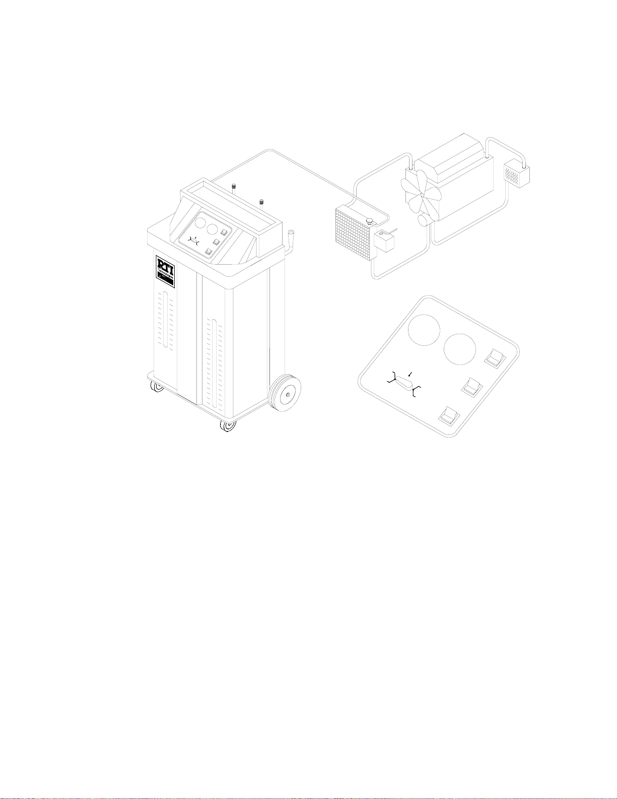
COMPONENT DESCRIPTION
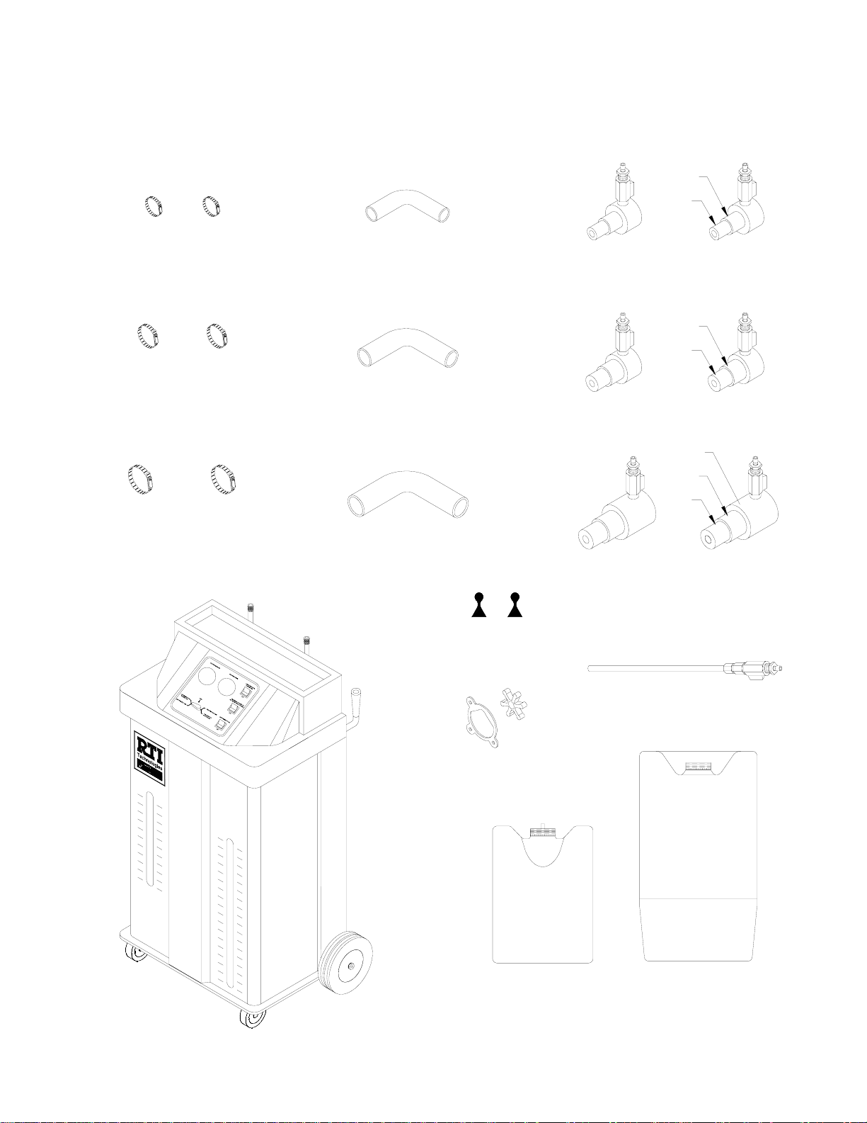
Unpack all components and verify quantities per this illustration.
Contact RTI if any items are missing or damaged.
Small Hose Clamps
Large Hose Clamps
Extra Large Hose Clamps
1-1/4
Small Adapter Hose
1-1/2
Large Adapter Hose
2-1/4
Extra Large Adapter Hose
1-3/8
1-3/4
2-1/2
1-3/8
1-1/4
Small Step Adapters
1-3/4
1-1/2
Large Step Adapters
2-1/2
2-1/4
2
Extra Large Step Adapters
Green Hose
Black Hose
Level Magnets
Impeller & Gasket
New Coolant
Tank
(Qty=3)
Wand
Waste Tank
Page 2
Page 4
SAFETY PRECAUTIONS
WARNING: FAILURE TO FOLLOW THESE PRECAUTIONS CAN RESULT IN
SERIOUS INJURY OR DEATH.
C Read and understand the Operation Manual completely before operating this unit.
C Always wear proper eye and skin protection when operating and maintaining this
equipment.
C Take precautions to keep clothing, hair, hands, hoses, etc. away from all moving
parts on the vehicle.
C Automotive cooling systems can be under pressure and extremely hot. Use extreme
caution when removing caps and hoses.
C Coolants are poisonous to people and animals and are also corrosive. Clean up any
spills immediately.
CAUTION: FAILURE TO FOLLOW THE PRECAUTIONS AS OUTLINED IN THE
OPERATION MANUAL CAN RESULT IN DAMAGE TO THE ENGINE,
VEHICLE OR EQUIPMENT WHICH WILL NOT BE SUPPORTED OR
COVERED UNDER WARRANTY.
C Do not allow waste coolant tank to overflow. Immediately clean up any coolant
spills. Damage to the vehicle and equipment can result from the corrosiveness of
coolant.
C Continuous monitoring of the coolant replacement process is required.
Operation of Valves
VALVE OPEN VALVE CLOSED
Page 3
Page 5
The MCX-2S was carefully packaged by RTI to
arrive without damage. Report any evidence of
damage immediately by calling RTI Technical
Support at 800-468-2321.
Mon. - Fri. 8AM - 5PM (Eastern Time)
Sat. - Sun. 8AM - 12PM (Eastern Time)
Following are the steps required to prepare the
MCX-2S for operation:
SET UP
Conventional
Green Gold
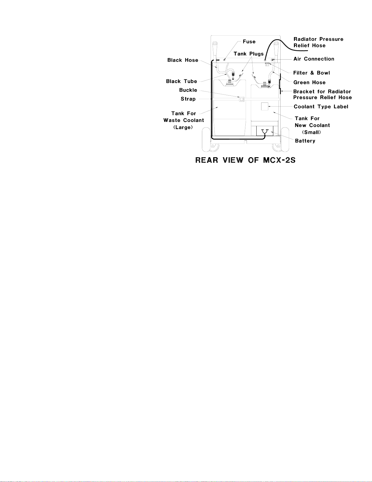
1. Remove all packing materials. Press sides of buckle
to release black web strap on rear of unit. Remove
the tanks and the accessory cartons from their
shipping position. There are three small New Coolant
Tanks and one large Waste Coolant Tank.
2. Press down on the levers on the front casters to lock
them. This will keep the MCX-2S from moving as
tanks are installed and connected.
3. Labels are provided to attach to the new coolant tanks
to identify the type of coolant. Peel off the protective
backing cover and place the appropriate label on the
narrow side of the new coolant tank. Attach the label
on the side closest to the brass hose connection
fitting and large fill cap.
4. Unscrew the large cap and fill one of the New Coolant
Tanks with coolant and water. Refer to the
specifications of the coolant manufacturer for the
correct proportions of water and coolant. Replace the
cap.
5. Pull the Tank Plug out of the port in the large cap. A
strap keeps the plug handy for use when carrying the
tank to other areas to avoid splashing.
6. Set the New Coolant Tank into the right side of the
MCX-2S on the shelf above the Battery. The brass
hose connection fitting should be closest to the rear
of the MCX-2S. The coolant type label should be
visible as shown above when the tank is positioned
correctly.
7. Connect the Green Hose to the brass quick connect
fitting on the New Coolant Tank. A sleeve on the
hose fitting can be slid away from the end of the fitting
to make connection and disconnection easy.
9. Connect the Black Hose to the quick connect fitting on
the Waste Tank. A sleeve on the fitting can be slid
away from the end of the fitting to make connection
and disconnection easy.
10. Pull the Tank Plug out of the port in the large cap on
the Waste Tank. A strap keeps the plug handy for use
when carrying the tank to other areas to avoid
splashing.
11. Insert the small diameter Black Tube into the hole in
the large cap on the Waste Coolant Tank. This tube
hangs above the Waste Tank. Do not pull on the
hose. Do not confuse this tube with the Radiator
Pressure Relief Hose on the upper right corner of the
MCX-2S.
12. Press sides of buckle on strap and insert mating end
of buckle to secure the tanks in place.
13. Lay the green and black hoses over the hose storage
bracket on the rear of the MCX-2S. Wrap the Radiator
Pressure Relief Hose on the bracket on the right side
of the rear of the MCX-2S.
14. Install 12 volt battery (not supplied with unit) in lower
right compartment. Set all selector switches to OFF.
Connect cable using supplied hardware. Connect
black terminal to negative (-) battery post and red
terminal to positive (+) battery post.
15. Release the locks on the front casters by lifting up on
the levers.
16. Refer to Page 2 and check that all accessory parts
were received. The accessory parts are packed in
cartons included with the MCX-2S.
8. Set the Waste Coolant Tank into the left side of the
MCX-2S. The Hose connection fitting should be
closest to the front of the MCX-2S.
Page 4
Page 6
RELIEVING RADIATOR PRESSURE
WARNING: Coolant in the vehicle cooling system may be extremely hot and
under great pressure. Wear safety glasses and use protective
clothing and gloves. Use extreme caution when removing
radiator cap and hoses.
Clear Hose
Radiator
Hose
Green Hose
S
Y
S
T
E
M
P
R
E
S
S
U
R
E
S
Y
S
T
E
M
V
A
C
U
U
M
L
O
W
E
R
&
R
O
A
V
D
E
I
R
A
F
T
L
O
O
R
L
O
W
E
R
&
R
O
A
V
E
D
R
I
A
F
T
L
O
T
O
E
R
W
E
S
M
P
T
Y
W
A
S
T
E
T
A
N
K
W
O
F
F
E
X
F
T
C
I
L
H
L
A
R
N
A
G
D
E
I
A
C
T
O
O
O
R
L
&
A
N
O
T
V
O
E
R
R
F
L
O
W
E
X
C
H
A
N
G
E
C
O
O
F
O
F
L
F
A
I
L
N
L
T
R
&
A
O
D
V
I
A
E
T
R
E
O
F
M
L
R
P
O
T
W
Y
W
A
S
T
E
T
A
N
K
O
F
F
Black Hose
Radiator
E
M
P
T
Y
W
Overflow
L
O
W
E
R
&
O
R
A
V
D
E
R
I
A
F
T
L
O
O
R
W
A
S
T
E
T
A
N
K
Water
Pump
T
E
S
T
&
E
X
C
F
I
L
L
R
A
O
D
V
E
R
F
L
Engine
Block
S
Y
S
T
E
M
P
R
E
S
S
U
R
E
S
Y
S
T
E
M
V
A
C
U
U
M
E
X
F
C
I
L
H
L
A
R
N
A
G
D
E
I
A
C
T
O
O
O
R
&
O
H
A
N
G
E
C
O
O
L
A
N
T
I
A
E
T
M
O
R
P
O
T
W
O
F
F
V
O
F
F
Y
W
A
S
T
E
T
A
N
K
Heater
Core
L
O
W
E
R
&
R
O
A
V
D
E
I
R
A
F
T
L
O
O
R
W
O
F
F
L
A
N
T
E
O
R
R
F
L
O
W
NOTE: The MCX-2S does not need to be connected to power for the following.
The MCX-2S will relieve the pressure in a hot-car radiator by drawing a vacuum on the
overflow port on the radiator cap.
Connect shop air (55 to 100 PSI) to the port on the rear of the MCX-2S. This will cause
a vacuum to be pulled on the small diameter clear hose, also connected to the rear.
Connect clear hose to the overflow port on the radiator cap as shown above.
The system Vacuum Gauge on the MCX-2S control panel indicates the vacuum level
which will increase until the radiator cap opens and relieves the pressure. As the
pressure releases a small amount of coolant will be seen flowing in the clear hose.
When the pressure has been relieved, the radiator cap will again close and the vacuum
level will increase and become steady on the gauge.
The radiator cap can now be slowly and carefully removed.
Disconnect shop air from rear port.
Page 5
Page 7

LOWERING COOLANT LEVEL
Green Hose
S
Y
S
T
E
M
P
R
E
S
S
U
R
E
S
Y
S
T
E
M
V
A
C
U
U
M
L
O
W
E
R
&
R
O
A
V
D
E
I
R
A
T
F
O
L
O
R
L
O
W
E
R
&
O
R
A
V
D
E
R
F
L
O
W
E
M
P
T
Y
W
A
S
T
E
T
A
N
K
W
O
F
F
I
A
T
O
T
R
E
E
S
X
T
F
I
C
L
H
L
A
R
N
A
G
D
E
I
A
C
T
O
O
O
R
L
&
A
N
O
T
V
O
E
R
R
F
L
O
W
E
X
C
H
A
N
G
E
C
O
O
F
O
F
L
A
F
N
I
L
T
L
R
&
A
O
D
V
I
A
E
T
R
E
O
F
M
L
R
P
O
T
W
Y
W
A
S
T
E
T
A
N
K
O
F
F
Black Hose
Radiator
Hose
Radiator
Wand
Overflow
L
O
W
E
R
&
O
V
E
E
M
P
T
Y
W
A
S
T
E
T
Engine
Block
Water
Pump
S
Y
S
T
E
M
P
R
E
S
S
U
R
E
R
A
D
I
R
A
F
T
L
O
T
O
R
E
W
S
T
A
N
K
E
X
C
H
A
N
G
E
C
O
O
O
L
F
A
I
N
L
L
T
&
R
A
O
D
V
I
E
A
R
T
E
O
F
M
L
R
P
O
T
W
Y
W
A
S
T
E
T
A
N
K
O
F
F
Heater
Core
S
Y
S
T
E
M
V
A
C
U
U
M
L
O
W
E
R
&
R
O
A
V
D
E
I
R
A
F
T
L
O
O
R
W
O
F
F
E
X
F
C
I
L
H
L
A
R
N
A
G
D
E
I
A
C
T
O
O
O
R
L
&
A
N
O
T
V
O
E
R
R
F
L
O
W
F
F
WARNING: Coolant in the vehicle cooling system may be extremely hot and
under great pressure. Wear safety glasses and use protective
clothing and gloves. Use extreme caution when removing
radiator cap and hoses.
1. Slowly and carefully remove the cap from the radiator.
2. Remove cap from overflow container.
3. Attach the wand to the black hose. Close the valve.
4. Turn control valve to LOWER RADIATOR & OVERFLOW.
5. Press the top of LOWER RADIATOR & OVERFLOW selector switch to turn on
pump.
6. Use the Wand to empty the overflow container and lower the level of coolant
in the radiator to a level just below the upper hose connecting the radiator to
the engine. Open valve on wand as required.
VERY IMPORTANT
Open valve on wand only while end is in fluid.
Do not suck air as the pump may loose its prime
7. Press bottom of LOWER RADIATOR & OVERFLOW selector switch to turn off
pump.
8. Replace caps on the radiator and overflow container.
Page 6
Page 8

CONNECTING TO THE COOLANT SYSTEM
The MCX-2S can be connected to the cooling system in either of the configurations
shown below. The choice is dependent on the ease of accessability to the hose
connections.
1. Disconnect the radiator hose from either the engine or the radiator.
2. Select an Adapter Hose with the same inner diameter as the radiator hose and
connect at the point the radiator hose was disconnected using a clamp.
3. Install Step Adapters in the Adapter Hose and the radiator hose using clamps.
Make sure the outside diameter of the Step Adapters is the same as the inner
diameter of the radiator hose.
4. Connect the Green and Black hoses from the MCX-2S to the two Step
Adapters as shown in the illustrations. See next page for special hookups.
5. Open the valves on the two Step Adapters.
Green Hose
Black Hose
S
Y
S
T
E
M
P
R
E
S
S
U
R
E
S
Y
S
T
E
M
V
A
C
U
U
M
L
O
W
E
&
R
O
R
V
A
E
D
R
I
A
F
T
L
O
O
R
L
O
W
E
R
&
R
O
A
V
D
E
R
I
A
F
T
L
O
O
R
W
E
M
P
T
Y
W
A
S
T
E
T
A
N
K
W
O
F
F
T
E
E
S
X
F
T
C
I
L
H
L
A
R
N
A
G
D
E
I
A
C
T
O
O
O
R
L
A
&
N
O
T
V
O
E
R
R
F
L
O
W
E
X
C
H
A
N
G
E
C
O
O
F
O
F
L
F
A
I
L
N
L
T
&
R
A
O
D
V
I
A
E
E
T
R
O
M
F
L
R
P
O
T
W
Y
W
A
S
T
E
T
A
N
K
O
F
F
Connecting at Engine
Adapter
Hose
Radiator
Hose
Radiator
Step
Adapters
Overflow
Water
Pump
Engine
Block
L
O
W
E
R
&
R
O
A
V
E
D
R
I
A
F
T
L
O
O
R
W
E
M
P
T
Y
W
A
S
T
E
T
A
N
K
Heater
Core
Green Hose
Black Hose
S
Y
S
T
E
M
P
R
E
S
S
U
R
E
S
Y
S
T
E
M
V
A
C
U
U
M
L
O
W
E
&
R
O
R
V
A
E
D
R
I
A
F
T
L
O
O
R
W
O
F
F
T
E
E
S
X
T
F
C
I
L
H
L
A
R
N
A
G
D
E
I
A
C
T
O
O
O
R
L
A
&
N
O
T
V
O
E
R
R
F
L
O
W
E
X
C
H
A
N
G
E
C
O
O
F
O
F
F
L
A
I
L
N
L
T
&
R
A
O
D
V
I
E
A
T
R
E
O
F
M
R
L
P
O
T
W
Y
W
A
S
T
E
T
A
N
K
O
F
F
Connecting at Radiator
Radiator
Hose
Adapter
Hose
Radiator
Step
Adapters
Overflow
Water
Pump
Engine
Block
Heater
Core
Page 7
Page 9

SPECIAL HOOKUPS
Special Hookup 1) It may be necessary to reverse the hoses during the coolant
replacement procedure on the following pages for systems with
a reverse-connected thermostat. See note after Step 7 for the
symptoms of this situation.
Special Hookup 2) Some cooling systems do not have a cap on the radiator.
Instead, there is a single cap on the overflow tank as shown in
the illustration below.
The hoses to and from the overflow tank must be pinched using
hose pinching pliers during the coolant replacement procedure
on the following pages.
Failure to pinch these hoses will cause fluid to be forced out of
the vented cap on the overflow tank during the coolant
replacement procedure.
Radiator
Hose
PINCH
HOSE
Step
Adapters
Overflow
Adapter
Hose
Water
Pump
PINCH
HOSE
Engine
Block
Heater
Core
Page 8
Page 10

COOLANT REPLACEMENT
Once the MCX-2S is connected as described on the preceding pages it is ready to
replace the old coolant with new coolant.
Green Hose
S
Y
S
T
E
M
P
R
E
S
S
U
R
E
S
Y
S
T
E
M
V
A
C
U
U
M
L
O
W
E
R
&
O
R
A
V
D
E
I
R
A
F
T
O
L
O
R
L
O
W
E
R
&
O
R
A
V
E
D
R
I
A
F
T
L
O
T
O
R
E
E
W
S
M
T
P
T
Y
W
A
S
T
E
T
A
N
K
W
O
F
F
E
X
F
C
I
L
H
L
A
R
N
A
G
D
E
I
A
C
T
O
O
O
R
L
&
A
N
O
T
V
E
O
R
R
F
L
O
W
E
X
C
H
A
N
G
E
C
O
O
F
O
F
L
F
A
I
N
L
L
T
&
R
A
O
D
V
I
E
A
E
R
T
M
F
O
P
L
R
O
T
Y
W
W
A
S
T
E
T
A
N
K
O
F
F
Scales for the tank levels are
graduated in quarts and liters
1 Gallon = 4 Quarts.
Black Hose
Radiator
Hose
Radiator
Step
Adapters
Overflow
E
M
P
T
Y
W
A
Adapter
Hose
Engine
Block
Water
Pump
S
Y
S
T
E
M
P
R
E
S
S
U
R
E
S
Y
S
T
E
L
O
W
E
R
&
R
O
A
V
D
E
R
I
A
F
T
L
O
T
O
R
E
W
S
S
T
E
T
A
N
T
K
E
X
C
H
A
N
G
E
C
O
O
L
F
A
I
L
N
L
&
R
A
O
D
V
I
E
A
R
T
F
O
L
R
O
W
E
F
I
L
L
R
O
F
F
T
E
M
P
T
Y
W
A
S
T
E
T
A
N
K
O
F
F
Heater
Core
M
V
A
C
U
U
M
L
O
W
E
R
&
R
O
A
V
D
E
I
R
A
F
T
L
O
O
R
W
O
F
F
X
C
H
A
N
A
G
D
E
I
A
C
T
O
O
O
R
L
&
A
N
O
T
V
O
E
R
R
F
L
O
W
1. Determine the capacity and type of coolant for the vehicle cooling system. Refer to
the vehicle Owner’s Manual.
2. Make sure the New Coolant Tank (left slot on front) is filled with the correct coolant
and at a level higher than the amount required to fill the coolant system to full
capacity.
3. Check the Waste Tank (right slot on front) to make sure the level is low enough to
accept the full capacity of coolant in the vehicle cooling system.
Continued on next page . . .
Page 9
Page 11

COOLANT REPLACEMENT
8 Quarts
QUARTS
30
28
26
24
22
20
18
16
14
12
10
8
LITERS
28
26
24
22
20
18
16
14
12
10
8
6
4
2
4. Set one of the Level Magnets at the fluid level in the New Coolant Tank (24 in above
drawing). Determine the amount of coolant to be exchanged (8 Quarts for example)
and position the other Level Magnet that many quarts below the other magnet (16
in above drawing).
5. Turn control valve to EXCHANGE COOLANT.
6. Press the top of EXCHANGE COOLANT OR FILL RADIATOR & OVERFLOW
selector switch to turn on the pump.
7. Watch the level of coolant as it lowers in the New Coolant Tank. Press the bottom
of the EXCHANGE COOLANT OR FILL RADIATOR & OVERFLOW selector switch
when it reaches the lower Level Magnet. This will stop the transfer of coolant.
6
4
2
If the pump is running and the new coolant level does not go down:
Try reversing the connections of the green and black hoses.
Page 10
Page 12

TEST COOLANT SYSTEM FOR LEAKS
The MCX-2S can be used to check the coolant system for leaks. The coolant system
is pressurized and the System Pressure Gauge on the MCX-2S is monitored for a drop
in pressure which would indicate a system leak.
Green Hose
Black Hose
S
Y
S
T
E
M
P
R
E
S
S
U
R
E
S
Y
S
T
E
M
V
A
C
U
U
M
L
O
W
E
R
&
O
R
A
V
D
E
I
R
A
F
T
L
O
O
R
L
O
W
E
&
R
O
R
V
A
E
D
R
I
A
F
T
L
O
T
O
E
R
E
W
S
M
T
P
T
Y
W
A
S
T
E
T
A
N
K
F
I
L
L
&
O
V
E
W
O
F
F
E
X
F
C
I
L
H
L
A
R
N
A
G
D
E
I
A
C
T
O
O
O
R
L
&
A
N
O
T
V
E
O
R
R
F
L
O
W
E
X
C
H
A
N
G
E
C
O
O
F
O
F
L
A
N
T
R
A
D
I
A
R
E
T
M
F
O
L
P
R
O
T
W
Y
W
A
S
T
E
T
A
N
K
O
F
F
Radiator
Hose
Step
Adapters
Adapter
Hose
Engine
Block
Heater
Core
Water
Pump
Radiator
Overflow
L
O
W
E
R
&
O
R
A
V
E
R
F
L
E
M
P
T
Y
W
A
S
T
E
T
A
N
K
S
Y
S
T
E
M
P
R
E
S
S
U
R
E
S
Y
S
T
E
M
V
A
C
U
U
M
L
O
W
E
R
&
O
R
A
V
D
E
I
R
A
F
T
L
O
O
R
W
O
D
I
A
T
O
T
O
E
R
W
S
T
E
X
C
H
A
N
G
E
C
O
O
L
F
A
I
L
N
L
T
&
R
A
O
D
V
I
E
A
E
R
T
M
O
F
L
P
R
O
T
W
Y
W
A
S
T
E
T
O
F
F
F
F
E
X
F
C
I
L
H
L
A
R
N
A
G
D
E
I
A
C
T
O
O
O
R
L
&
A
N
O
T
V
O
E
R
R
F
L
O
W
O
F
F
A
N
K
The MCX-2S should be connected a shown above.
1. Turn control valve to TEST.
2. Press the top of EXCHANGE COOLANT OR FILL RADIATOR & OVERFLOW
selector switch to turn on the pump.
3. Watch the System Pressure Gauge and press the bottom of the EXCHANGE
COOLANT OR FILL RADIATOR & OVERFLOW selector switch when the
pressure reaches 10 to 13 PSI.
4. The coolant system is now pressurized. Monitor the pressure for a constant
reading. A coolant system leak is indicated if the pressure falls.
Page 11
Page 13

COMPLETING THE JOB
All used coolant in the vehicle cooling system has now been replaced with new coolant.
The following steps will complete the job.
Green Hose
Black Hose
S
Y
S
T
E
M
P
R
E
S
S
U
R
E
S
Y
S
T
E
M
V
A
C
U
U
M
L
O
W
E
&
R
O
R
A
V
D
E
R
I
A
F
T
L
O
O
R
L
O
W
E
R
&
O
R
V
A
D
E
I
R
A
F
T
L
O
T
O
R
E
E
W
S
M
T
P
T
Y
W
A
S
T
E
T
A
N
K
F
I
&
O
W
O
F
F
E
X
F
C
I
L
H
L
A
R
N
A
G
D
E
I
A
C
T
O
O
O
R
L
A
&
N
O
T
V
O
E
R
R
F
L
O
W
E
X
C
H
A
N
G
E
C
O
O
F
O
F
L
A
L
N
L
T
R
A
D
V
I
E
A
E
R
T
M
O
F
L
P
R
O
T
W
Y
W
A
S
T
E
T
A
N
K
O
F
F
Radiator
Hose
Wand
Engine
Block
Heater
Core
Water
Pump
Radiator
Overflow
L
O
W
E
R
&
R
O
A
V
E
R
F
L
E
M
P
T
Y
W
A
S
T
E
T
A
N
K
S
Y
S
T
E
M
P
R
E
S
S
U
R
E
S
Y
S
T
E
M
V
A
C
U
U
M
D
I
A
T
O
T
O
R
E
W
S
T
E
X
C
H
A
N
G
E
C
O
O
L
F
A
I
L
N
L
&
R
A
O
D
V
I
E
A
R
T
O
F
L
R
O
W
E
X
F
C
I
L
H
L
A
R
N
A
G
D
E
I
A
T
O
R
&
O
F
F
T
E
M
P
T
Y
W
A
S
T
E
T
A
N
K
O
F
F
1. Close the valves on the Step Adapters.
2. Disconnect the black and green hoses from the Step Adapters.
3. Install Wand on black hose. Close the valve.
4. Remove the cap from the radiator.
L
O
W
E
R
&
R
O
A
V
D
E
R
I
A
F
T
L
O
O
R
W
O
F
F
C
O
O
L
A
N
O
T
V
O
E
R
R
F
L
O
W
5. Turn control valve to LOWER RADIATOR & OVERFLOW.
6. Press top of LOWER RADIATOR & OVERFLOW selector switch to turn on
pump.
7. Use the Wand to lower the level of coolant in the radiator to a level just below
the upper hose where the Step Adapter is attached. Open valve on Wand as
required.
Continued on next page . . .
Page 12
Page 14

COMPLETING THE JOB
Green Hose
S
Y
S
T
E
M
P
R
E
S
S
U
R
E
S
Y
S
T
E
M
V
A
C
U
U
M
L
O
W
E
R
&
R
O
A
V
D
E
I
R
A
F
T
L
O
O
R
L
O
W
E
R
&
O
R
A
V
D
E
I
R
A
F
T
L
O
O
T
R
E
W
E
S
M
T
P
T
Y
W
A
S
T
E
T
A
N
K
F
&
W
O
F
F
E
X
F
C
I
L
H
L
A
R
N
A
G
D
E
I
A
C
T
O
O
O
R
L
A
&
N
O
T
V
O
E
R
R
F
L
O
W
E
X
C
H
A
N
G
E
C
O
O
F
O
F
L
A
I
N
L
L
T
R
A
O
D
V
I
A
E
E
T
R
O
M
F
R
L
P
O
T
W
Y
W
A
S
T
E
T
A
N
K
O
F
F
Black Hose
Radiator
Hose
Wand
Engine
Block
Heater
Core
Water
Pump
Radiator
Overflow
L
O
W
E
R
&
R
O
A
V
D
E
R
F
L
O
E
M
P
T
Y
W
A
S
T
E
T
A
N
K
S
Y
S
T
E
M
P
R
E
S
S
U
R
E
S
Y
S
T
E
M
V
A
C
U
U
M
L
O
W
E
R
&
R
O
A
V
D
E
I
R
A
F
T
L
O
O
R
W
O
F
I
A
T
O
T
R
E
W
S
T
E
X
C
H
A
N
G
E
C
O
O
L
F
A
I
N
L
T
L
R
&
A
O
D
V
I
A
E
T
R
E
O
M
F
L
R
P
O
T
W
Y
W
A
S
T
E
T
O
F
F
F
E
X
F
C
I
L
H
L
A
R
N
A
G
D
E
I
A
C
T
O
O
O
R
L
&
A
N
O
T
V
O
E
R
R
F
L
O
W
O
F
F
A
N
K
8. Remove the Step Adapters from the radiator hose and the Adapter Hose.
9. Remove the Adapter Hose and reattach the radiator hose.
10. Remove the overflow container cap.
11. Install the Wand on the green hose. Close the valve.
12. Turn control valve to FILL RADIATOR & OVERFLOW.
13. Press the top of EXCHANGE COOLANT OR FILL RADIATOR & OVERFLOW
selector switch to turn on the pump.
14. Open the valve on the Wand to fill the radiator and overflow container to the
recommended levels.
15. Replace the radiator cap and overflow container cap.
16. Press the bottom of the EXCHANGE COOLANT OR FILL RADIATOR &
OVERFLOW selector switch and disconnect power cord.
Page 13
Page 15

CHANGING COOLANT TYPE
The MCX-2S has a means for easily using different types of coolants. A special feature
is the clearing process which purges coolant from the hoses and pumps prior to
changing the new coolant tank. The MCX-2S must be connected to a battery during
this procedure.
Green Hose
S
Y
S
T
E
M
P
R
E
S
S
U
R
E
S
Y
S
T
E
M
V
A
C
U
U
M
L
O
W
E
R
&
R
O
A
V
D
E
I
R
A
T
F
O
L
O
R
L
O
W
E
R
&
R
O
A
V
D
E
I
R
A
F
T
L
O
O
R
W
E
M
P
T
Y
W
A
S
T
E
T
A
N
K
W
O
F
F
T
E
E
S
X
F
T
C
I
L
H
L
A
R
N
A
G
D
E
I
A
C
T
O
O
O
R
L
A
&
N
O
T
V
O
E
R
R
F
L
O
W
E
X
C
H
A
N
G
E
C
O
O
F
O
F
L
F
A
I
N
L
L
T
&
R
A
O
D
V
I
A
E
E
T
R
O
M
F
R
L
P
O
T
Y
W
W
A
S
T
E
T
A
N
K
O
F
F
Black Hose
Green Hose
Adapter
Step
New Coolant Tank
(Small)
Wand
S
Y
S
T
E
M
P
R
E
S
S
U
R
E
S
Y
S
T
E
M
V
A
C
U
U
M
L
O
W
E
R
&
R
O
A
V
D
E
I
R
A
F
T
L
O
O
R
L
O
W
E
R
&
R
O
A
V
D
E
I
R
A
F
T
L
O
T
O
R
E
W
E
M
P
T
Y
W
A
S
T
S
E
T
T
A
N
K
E
X
C
H
A
N
G
E
C
O
F
I
L
L
&
R
A
O
D
V
I
E
A
R
T
O
F
L
R
O
W
E
X
F
C
I
L
H
L
R
A
D
O
F
O
F
L
A
N
T
E
M
P
T
Y
W
A
S
T
E
T
A
N
K
O
F
F
W
O
F
F
A
N
G
E
I
A
C
T
O
O
O
R
L
&
A
N
O
T
V
O
E
R
R
F
L
O
W
1. Slide the New Coolant Tank to the rear and sit it on the floor.
2. Disconnect the green hose from the tank and install a Step Adapter on the end.
Close the valve on the Step Adapter.
3. Close the valve and install the Wand on the long green hose.
4. Turn control valve to FILL RADIATOR & OVERFLOW.
5. Press the top of the EXCHANGE COOLANT OR FILL RADIATOR &
OVERFLOW selector switch to start the pump.
6. Insert the end of the Wand in the fill port of the New Coolant Tank. Open the
valve on the Wand and then open the valve on the Step Adapter. All coolant in
the hoses and pump will be emptied into the New Coolant Tank.
7. Close the valve on the Wand and Step Adapter. Press the bottom of the
EXCHANGE COOLANT OR FILL RADIATOR & OVERFLOW selector switch
to turn off the pump.
8. Remove the Step Adapter from the green hose and connect the hose to a New
Coolant Tank with a different type of coolant.
Continued on next page . . .
Page 14
Page 16

CHANGING COOLANT TYPE
Green Hose
S
Y
S
T
E
M
P
R
E
S
S
U
R
E
S
Y
S
T
E
M
V
A
C
U
U
M
L
O
W
E
R
&
R
O
A
V
D
E
I
R
A
F
T
L
O
O
R
L
O
W
E
R
&
R
O
A
V
D
E
I
R
A
F
T
L
O
T
O
R
E
E
W
S
M
T
P
T
Y
W
A
S
T
E
T
A
N
K
F
I
L
L
&
O
V
E
W
O
F
F
E
X
F
C
I
L
H
L
A
R
N
A
G
D
E
I
A
C
T
O
O
O
R
L
&
A
N
O
T
V
E
O
R
R
F
L
O
W
E
X
C
H
A
N
G
E
C
O
O
F
O
F
L
A
N
T
R
A
D
I
A
R
E
T
O
F
M
L
R
P
O
T
W
Y
W
A
S
T
E
T
A
N
K
O
F
F
Black Hose
Green Hose
Wand
S
Y
S
T
E
M
P
R
E
S
S
U
R
E
S
Y
S
T
E
M
V
A
C
U
U
M
L
O
W
E
R
&
R
O
A
V
D
E
I
R
A
F
T
L
O
O
R
W
L
O
W
E
R
&
R
O
A
V
D
E
I
R
A
F
T
L
O
O
T
R
E
W
E
M
P
T
Y
W
A
S
T
E
T
A
N
K
S
T
E
X
C
H
A
N
G
E
C
O
O
L
F
A
I
N
L
L
T
&
R
A
O
D
V
I
E
A
E
R
T
O
M
F
L
R
P
O
T
W
Y
W
A
S
T
O
F
F
O
F
F
E
X
F
C
I
L
H
L
A
R
N
A
G
D
E
I
A
C
T
O
O
O
R
L
&
A
N
O
T
V
E
O
R
R
F
L
O
W
O
F
F
E
T
A
N
K
New Coolant Tank
(Small)
9. Press the top of the EXCHANGE COOLANT OR FILL RADIATOR &
OVERFLOW selector switch to start the pump.
10. Insert the end of the Wand in the fill port of the New Coolant Tank. Open the
valve on the Wand.
11. The pump will prime and hoses will fill with the new coolant.
12. Close the valve on the Wand when new coolant starts flowing.
13. Press the bottom of the EXCHANGE COOLANT OR FILL RADIATOR &
OVERFLOW selector switch to turn off the pump.
14. Place the cap on the New Coolant Tank and slide it into the MCX-2S.
Page 15
Page 17

EMPTYING THE WASTE TANK
The MCX-2S will pump the waste coolant directly from the Waste Tank into another
waste collection tank. A 12 volt battery will be required to power the MCX-2S.
S
Y
S
T
E
M
P
R
E
S
Green Hose
Black Hose
S
Y
S
T
E
M
P
R
E
S
S
U
R
E
S
Y
S
T
E
M
V
A
C
U
U
M
L
O
W
E
R
&
O
R
A
V
E
D
I
R
A
F
T
L
O
O
R
L
O
W
E
&
R
R
O
A
V
D
E
R
I
A
F
T
L
O
O
R
W
E
M
P
T
Y
W
A
S
T
E
T
A
N
K
W
O
F
F
T
E
E
S
X
F
T
C
I
L
H
L
A
R
N
A
G
D
E
I
A
C
T
O
O
O
R
L
&
A
N
O
T
V
O
E
R
R
F
L
O
W
E
X
C
H
A
N
G
E
C
O
O
F
O
F
L
F
A
I
N
L
L
T
&
R
A
O
D
V
I
E
A
R
T
E
F
O
M
R
L
P
O
T
W
Y
W
A
S
T
E
T
A
N
K
O
F
F
L
O
W
E
R
&
R
O
A
V
D
E
I
R
A
F
T
L
O
O
R
W
E
M
P
T
Y
W
A
S
T
E
T
A
N
K
S
U
R
E
S
Y
S
T
E
M
V
A
C
U
U
M
L
O
W
E
R
&
R
O
A
V
D
E
I
R
A
F
T
L
O
O
R
W
O
F
T
E
S
T
E
X
C
H
A
N
G
E
C
O
O
L
F
A
I
N
L
L
T
&
R
A
O
D
V
I
E
A
E
R
T
O
M
F
L
R
P
O
T
W
Y
W
O
F
F
F
E
X
F
C
I
L
H
L
A
R
N
A
G
D
E
I
A
C
T
O
O
O
R
L
&
A
N
O
T
V
O
E
R
R
F
L
O
W
O
F
F
A
S
T
E
T
A
N
K
Bulk Waste Container
1. Install the Wand on the black hose.
2. Turn the control valve to EMPTY WASTE TANK.
3. Press the top of the EMPTY WASTE TANK selector switch to start the pump.
4. Hold the Wand over the Bulk Waste Container and open the valve.
5. Waste coolant will be pumped directly from the MCX-2S Waste Tank into the
Bulk Waste Container.
6. The Waste Tank will empty and the pump will shut off. A float switch in the
Waste Tank controls this function.
7. Close the valve on the Wand when done.
8. Press the bottom of the EMPTY WASTE TANK selector switch.
Note: The Waste Tank has a float switch which detects when the tank is empty and
shuts off the waste pump.
Page 16
Page 18

REPLACEMENT PARTS - POWS Numbers
Visit our web-site at www.rtitech.com
1-1/4
1-1/2
2-1/4
1-1/4
1-1/2
1-3/8
1-3/4
1-3/8
1-3/4
2-1/2
Small Adapter Hose
(Includes 2 Clamps)
Large Adapter Hose
(Includes 2 Clamps)
Extra Large Adapter Hose
(Includes 2 Clamps)
Small Step Adapter
Large Step Adapter
62105
62108
62109
62106
62110
3-Bolt Style
Impeller & Gasket
(For Waste Pump M2)
4-Bolt Style
Impeller & Gasket
(For Waste Pump M2)
New Coolant Tank
Waste Tank
62116
62297
62117
62118
2-1/2
2-1/4
2
Extra Large Step Adapter 62114
Wand
Fuse 15 AMP
62107
62115
Conventional
Green Gold
Extended
Life
Level Magnet
(Package of 6)
Tank Label
Conventional Green Gold
Tank Label
Extended Life - Orange
62119
62120
62121
Technical Support: 800-468-2321
Mon. - Fri. 8AM - 5PM (Eastern Time)
Sat. - Sun. 8AM - 12PM (Eastern Time)
Page 17
Page 19

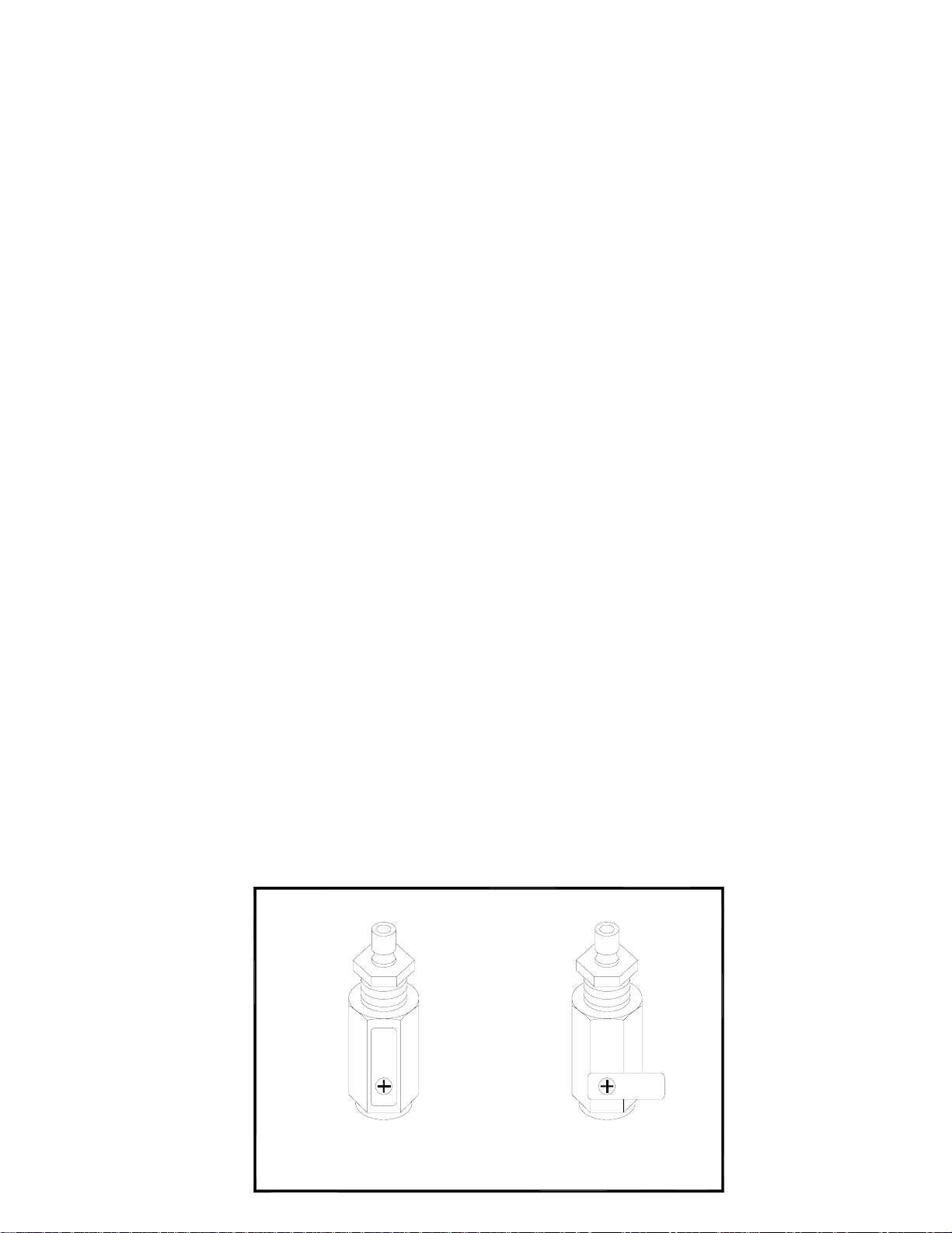
WASTE PUMP IMPELLER REPLACEMENT
The waste pump impeller may require periodic replacement. The concentration of
impurities in recovered waste coolant affects the life of the pump impeller. Changing
the impeller is quick and easy as follows:
1. The Waste Pump is accessible through a hole in the Hose Holder on the rear
of the MCX-2S.
2. Remove screws.
3. Remove cover plate, gasket and worn impeller.
4. Coat new impeller with Vaseline
®
petroleum jelly.
5. Align flats and press impeller onto shaft.
6. Attach new gasket and cover plate.
Pump
Housing
Impeller
Gasket
Cover Plate
Cover Plate
Gasket
Impeller
Pump
Housing
Screw
Screw
3-Bolt Style 4-Bolt Style
Impeller & Gasket Impeller & Gasket
Part Number: 62116 Part Number: 62297
Page 18
Page 20

FLOW & WIRING DIAGRAM
Page 19
 Loading...