

Page 1

OPERATION MANUAL
MCX-2
Multiple Coolant Exchanger
S
Y
S
T
E
M
P
R
E
S
S
U
R
E
S
Y
S
T
E
M
V
A
C
U
U
M
L
O
W
E
R
&
R
O
A
V
D
E
I
A
R
F
T
L
O
O
R
L
O
W
E
R
&
O
R
V
A
E
D
R
I
A
F
T
L
O
O
R
W
E
M
P
T
Y
W
A
S
T
E
T
A
N
K
W
O
F
F
T
E
E
S
X
F
T
C
I
L
H
L
A
N
R
G
A
D
E
I
A
C
T
O
O
O
R
L
&
A
N
O
T
V
O
E
R
R
F
L
O
W
E
X
C
H
A
N
G
E
C
O
O
F
O
F
L
F
A
L
I
N
L
T
R
&
A
O
D
V
A
I
E
T
R
E
O
F
M
R
L
P
O
T
W
Y
W
A
S
T
E
T
A
N
K
O
F
F
4075 East Market Street
York, Pennsylvania USA
800-468-2321
www.rtitech.com
Manual Number 035-80804-00
Page 2

TABLE OF CONTENTS
Component Description ....................... 2
Safety Precautions .......................... 3
Set-up .................................... 4
Connection to Power ......................... 5
Relieving Radiator Pressure ................... 6
Lowering Coolant Level....................... 7
Connecting to the Coolant System .............. 8
Special Hookups ............................ 9
Coolant Replacement ....................... 10
Test Coolant System for Leaks ................ 11
Completing the Job ......................... 12
Changing Coolant Type ...................... 14
Emptying the Waste Tank .................... 16
Replacement Parts ......................... 17
Waste Pump Impeller Replacement ............ 18
Flow & Wiring Diagram ...................... 19
Page 1
Page 3
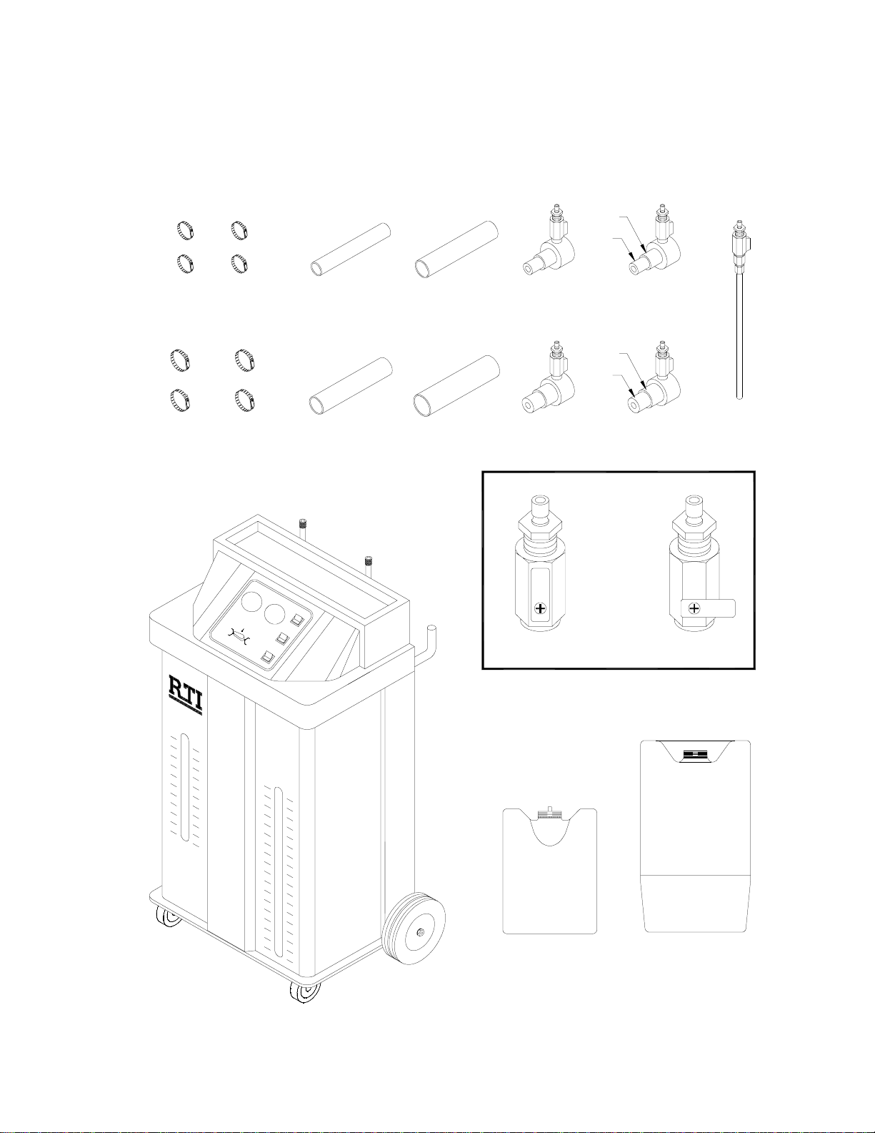
COMPONENT DESCRIPTION
Unpack all components and verify quantities per this illustration.
Contact RTI if any items are missing or damaged.
Small Hose Clamps
Large Hose Clamps
S
Y
L
O
W
E
R
&
R
O
A
V
D
E
I
R
A
T
F
L
O
O
T
R
E
E
W
S
M
T
P
T
Y
W
A
S
T
E
T
A
N
K
E
X
C
H
A
N
G
F
I
L
L
R
&
A
O
D
V
I
A
E
R
T
O
F
L
R
O
W
Green Hose
S
T
E
M
P
R
E
S
S
U
R
E
S
Y
S
T
E
M
V
A
C
U
U
M
L
O
W
&
O
V
O
F
F
E
X
F
C
I
L
H
L
A
R
N
A
G
D
E
I
A
C
T
O
O
O
R
L
A
&
N
O
T
V
O
E
R
R
F
L
O
W
E
C
O
O
F
O
F
L
A
N
T
E
M
P
T
Y
W
A
S
T
E
T
A
N
K
O
F
F
1-1/4
Small Adapter Hoses
1-1/2
Large Adapter Hoses
Black Hose
E
R
R
A
E
D
I
R
A
F
T
L
O
O
R
W
1-3/8
1-3/4
Small Step Adapters
Large Step Adapters
VALVE OPEN
1-3/8
1-1/4
1-3/4
1-1/2
Wand
VALVE CLOSED
New Coolant
Tank
(Qty=2)
Waste Tank
Page 2
Page 4

SAFETY PRECAUTIONS
WARNING: FAILURE TO FOLLOW THESE PRECAUTIONS CAN RESULT IN
SERIOUS INJURY OR DEATH.
C Read and understand the Operation Manual completely before operating this unit.
C Always wear proper eye and skin protection when operating and maintaining this
equipment.
C Take precautions to keep clothing, hair, hands, hoses, etc. away from all moving
parts on the vehicle.
C Automotive cooling systems can be under pressure and extremely hot. Allow the
cooling system to cool down and use extreme caution when removing caps and
hoses.
C Coolants are poisonous to people and animals and are also corrosiv e. Clean up any
spills immediately.
CAUTION: FAILURE TO FOLLOW THE PRECAUTIONS AS OUTLINED IN THE
OPERATION MANUAL CAN RESULT IN DAMAGE TO THE ENGINE,
VEHICLE OR EQUIPMENT WHICH WILL NOT BE SUPPORTED OR
COVERED UNDER WARRANTY.
C Do not allow waste coolant tank to overflow. Immediately clean up any coolant
spills. Damage to the vehicle and equipment can result from the corrosiveness of
coolant.
C Continuous monitoring of the coolant replacement process is required.
Page 3
Page 5
SET UP
Green Hose
Black Hose
S
Y
S
T
E
M
P
R
E
S
S
U
R
E
S
Y
S
T
E
M
V
A
C
U
U
M
L
O
W
E
&
R
O
R
A
V
D
E
R
I
A
F
T
L
O
O
R
L
O
W
E
R
&
R
O
A
V
D
E
A
I
R
F
T
O
L
T
O
E
R
E
W
S
M
T
P
T
Y
W
A
S
T
E
T
A
N
K
E
X
C
F
I
L
L
&
R
A
O
D
V
E
R
F
L
W
O
F
F
E
X
F
I
C
L
H
L
A
R
N
A
G
D
E
I
A
C
T
O
O
O
R
L
A
&
N
O
T
V
O
E
R
R
F
L
O
W
H
A
N
G
E
C
O
O
F
O
F
L
A
N
T
I
A
E
T
M
O
P
R
O
T
Y
W
W
A
S
T
E
T
A
N
K
O
F
F
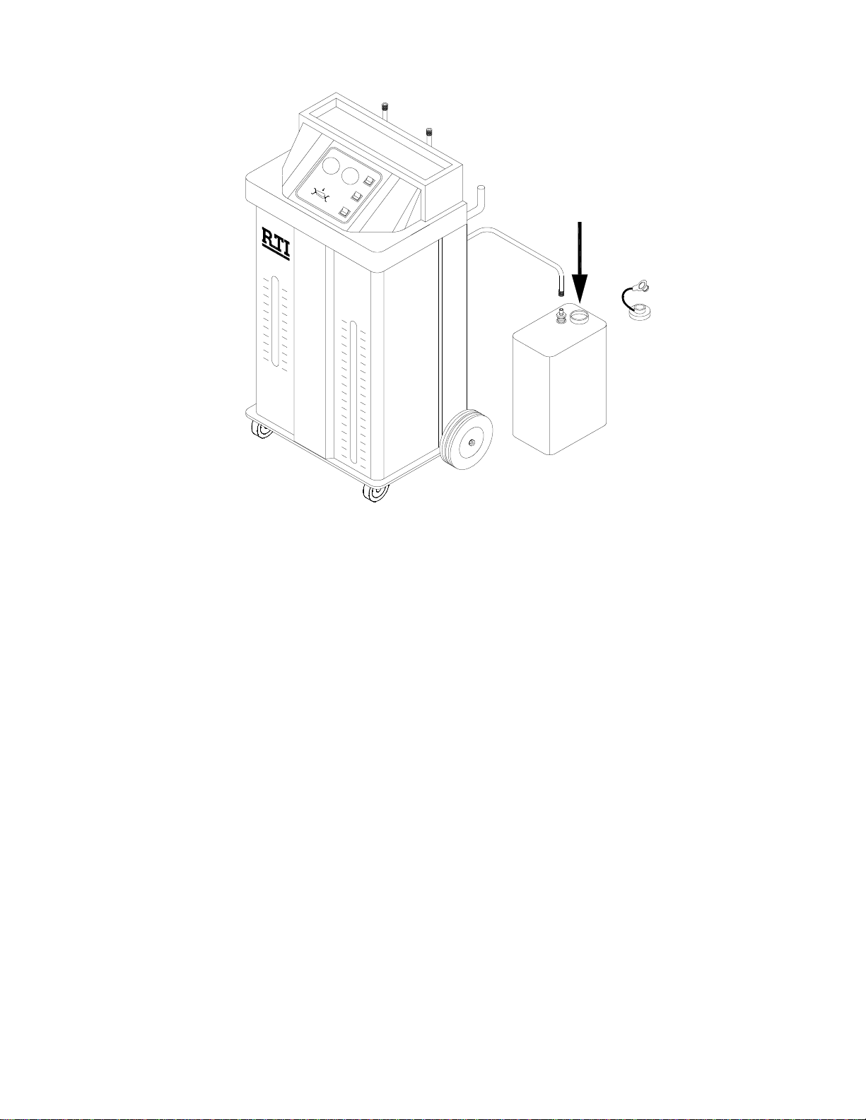
New Coolant
Green Hose
Tank C ap & Plug
Quick
Coupler
New Coolant Tank
(Small)
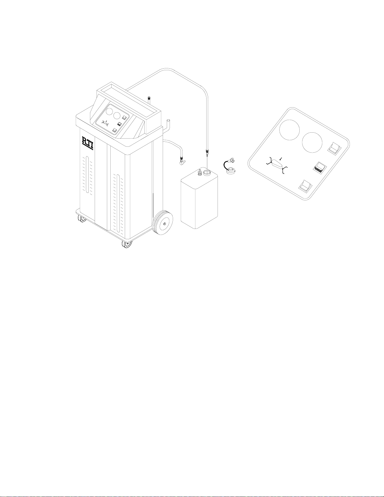
The MCX-2 has two tanks (plus an extra New Coolant Tank) which are installed and
connected from the rear. Quick connec t couplers are mounted on the hoses which
connect these tanks to the MCX-2. A green hose connects to the small New Coolant
Tank and a black hose connects to the large W aste Tank. The small diameter black
drain hose must be inserted into the hole in the cap of the Waste Tank.
1. Slide the New Coolant Tank to the rear and sit it on the floor.
2. Remove the tank cap and fill the tank with new coolant and water in the
proportion s specified by the coolant supplier. The tank can be disconnected
and moved to a bulk coolant storage area for filling if desired. A plug is
provided on the cap to prevent spillage during transport.
3. Replace the tank cap and position the tank in the MCX-2. Make sure the green
hose is securely connected. Slide the tank to the front so the liquid level can be
seen through the front panel slot.
4. Make sure the plugs are removed from the caps on the Waste Tank and
the New Coolant Tank. This is required for venting the tanks during
operation. The small diameter black drain hose must be inserted into the
hole in the cap of the Waste Tank.
5. Fasten the clips on the tank strap to secure the tanks in the MCX-2.
Page 4
Page 6
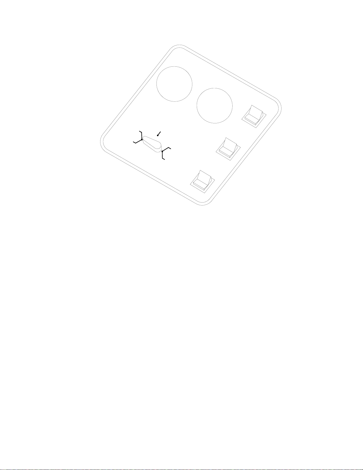
CONNECTION TO POWER
S
Y
S
T
E
M
P
R
E
S
S
U
R
E
S
Y
S
T
E
M
V
A
C
U
U
M
L
O
W
E
R
&
O
R
A
V
D
E
I
R
A
F
T
L
O
O
R
E
M
P
W
T
Y
W
A
S
T
E
T
A
N
K
T
E
S
T
E
X
C
H
A
N
G
E
C
O
O
F
I
L
L
&
O
V
L
A
N
R
A
D
E
R
F
T
I
A
T
O
L
R
O
W
E
M
P
T
Y
O
F
F
E
X
F
I
L
L
R
A
O
F
F
W
A
S
T
E
T
A
N
K
O
F
C
H
D
I
F
A
N
G
E
A
C
T
O
O
O
R
L
&
A
N
O
T
V
E
O
R
R
F
L
O
W
L
O
W
E
R
&
R
O
A
V
D
E
I
R
A
F
T
L
O
O
R
W
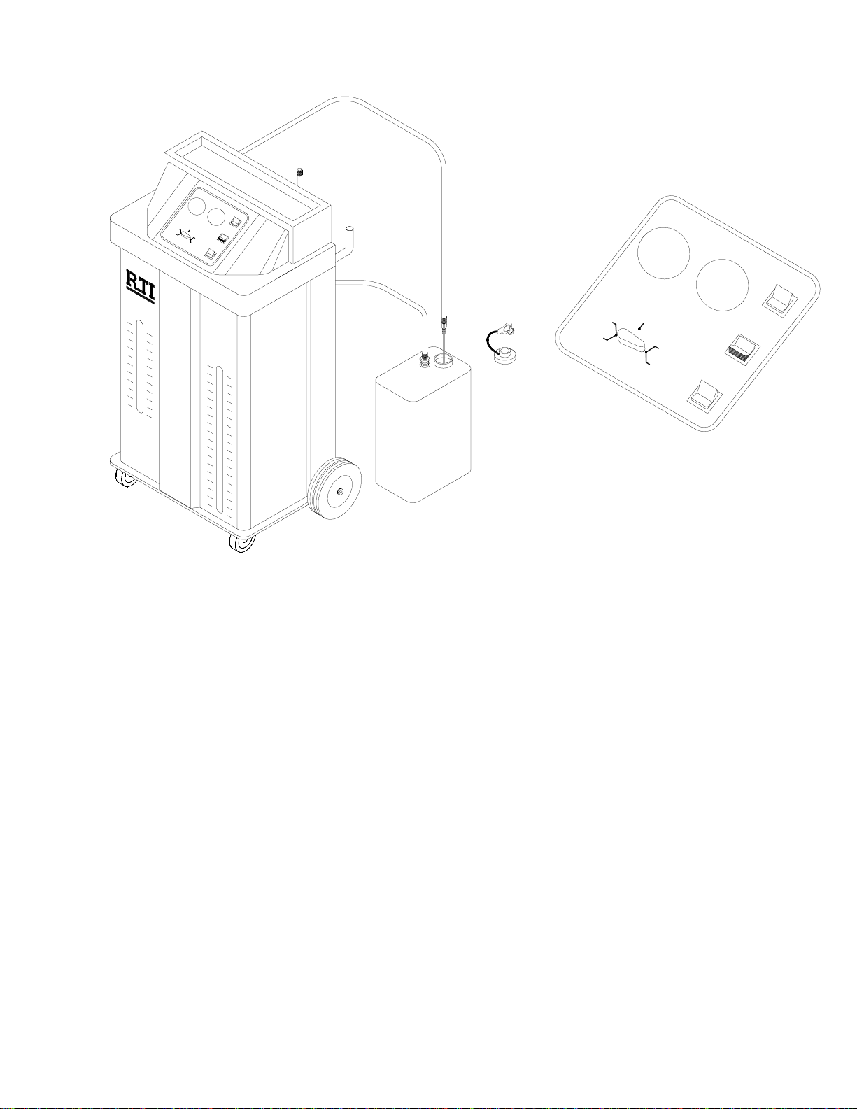
The MCX-2 control panel is illustrated above. Note that the bottom of all three selector
switches has been pressed which turns all functions off. Make sure all switches are
off before connecting the battery cable clips to the battery of the vehicle.
WARNING: Handle battery connection cable with extreme caution. Batteries
generate explosive gases during normal operation. Working in
the vicinity of a lead-acid or other automotive battery is
dangerous. Wear eye protection. Never smoke or allow a spark or
flame in the vicinity of the battery. Do not connect the black
power clip to the negati ve post of the battery to avoid a spark.
1. Verify that all switches are in the off position.
2. Connect the red power clip to the “+” (positive) post of the vehicle battery. The
battery must be 12 volt.
3. Connect black power clip to an engine ground (not the negative post of the
battery).
Page 5
Page 7

RELIEVING RADIATOR PRESSURE
WARNING: Coolant in the vehicle cooling system may be extremely hot and
under great pressure. Wear safety glasses and use protective
clothing and gloves. Use extreme caution when removing
radiator cap and hoses.
Clear Hose
Radiator
Hose
Green Hose
S
Y
S
T
E
M
P
R
E
S
S
U
R
E
S
Y
S
T
E
M
V
A
C
U
U
M
L
O
W
E
R
&
R
O
A
V
D
E
I
A
R
T
F
L
O
O
R
L
O
W
E
&
R
O
R
V
A
E
D
R
A
I
F
T
L
O
O
T
R
W
E
E
S
M
T
P
T
Y
W
A
S
T
E
T
A
N
K
W
O
F
F
E
F
X
C
I
L
L
H
A
R
N
A
G
D
E
I
A
C
T
O
O
O
R
L
&
A
O
N
T
V
E
O
R
R
F
L
O
W
E
X
C
H
A
N
G
E
C
O
O
O
F
F
L
A
F
N
L
I
T
L
&
R
A
O
D
V
I
E
A
E
R
T
O
M
F
L
R
P
O
T
Y
W
W
A
S
T
E
T
A
N
K
O
F
F
Black Hose
Radiator
E
M
P
T
Y
W
Overflow
L
O
W
E
R
&
R
O
A
V
D
E
I
R
A
F
T
L
O
O
W
A
S
T
E
T
A
N
K
Water
Pump
T
R
E
S
T
E
X
C
F
I
L
L
R
&
A
O
D
V
E
R
F
L
Engine
Block
S
Y
S
T
E
M
P
R
E
S
S
U
R
E
S
Y
S
T
E
M
V
A
C
U
U
M
E
X
F
C
I
L
H
L
A
R
N
A
G
D
E
I
A
C
T
O
O
O
R
&
O
V
H
A
N
G
E
C
O
O
I
A
T
O
R
O
W
F
O
F
L
A
N
T
E
M
P
T
Y
W
A
S
T
E
T
A
N
K
O
F
F
Heater
Core
L
O
W
E
R
&
R
O
A
V
D
E
I
R
A
F
T
L
O
O
R
W
O
F
F
L
A
N
T
O
E
R
R
F
L
O
W
NOTE: The MCX-2 does not need to be connected to power for the following.
The MCX-2 will relieve the pressure in a hot-car radiator by draw ing a v acuum on the
overflow port on the radiator cap.
Shop air (55 to 100 PSI), connected to the rear port of the MCX-2 causes a vacuum
to be pulled on the small diameter clear hose, also connected to the rear. This clear
hose is connected to the overflow port on the radiator cap as shown above.
The system Vacuum Gauge on the MCX-2 c ont rol panel indicates the vacuum level
which will increase until the radiator cap opens and relieves the pressure. As the
pressure releases a small amount of coola nt wil l be seen flowing in the clear hose.
When the pressure has been relieved, the radiator cap will again close and the vacuum
level will increase and become steady on the gauge.
The radiator cap can now be slowly and carefully removed.
Page 6
Page 8
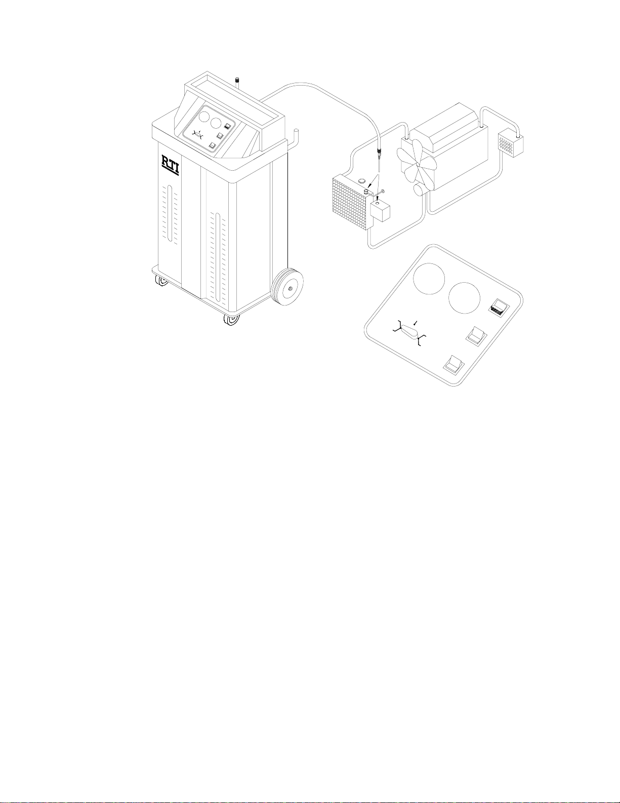
LOWERING COOLANT LEVEL
Green Hose
S
Black Hose
Y
S
T
E
M
P
R
E
S
S
U
R
E
S
Y
S
T
E
M
V
A
C
U
U
M
L
O
W
E
R
&
R
O
A
V
D
E
R
I
A
T
F
O
L
O
R
L
O
W
E
R
&
R
O
V
A
E
D
R
I
A
F
T
L
O
O
T
R
W
E
E
S
M
T
P
T
Y
W
A
S
T
E
T
A
N
K
W
O
F
F
E
X
F
C
L
I
H
L
A
R
N
A
G
D
E
I
A
C
T
O
O
O
R
L
&
A
N
O
T
V
O
E
R
R
F
L
O
W
E
X
C
H
A
N
G
E
C
O
O
F
O
F
L
F
A
I
L
N
L
T
R
&
A
O
D
V
A
I
E
R
T
E
F
O
M
L
R
P
O
T
W
Y
W
A
S
T
E
T
A
N
K
O
F
F
Radiator
Hose
Radiator
Wand
Overflow
L
O
W
E
R
&
R
O
A
V
E
R
F
L
E
M
P
T
Y
W
A
S
T
E
T
A
N
K
Engine
Block
Water
Pump
S
Y
S
T
E
M
P
R
E
S
S
U
R
E
S
Y
S
T
E
M
D
I
A
T
O
T
O
R
E
W
S
T
E
X
C
H
A
N
G
E
C
O
O
L
F
I
L
L
&
R
A
O
D
V
I
E
A
R
T
O
F
L
R
O
W
E
X
F
C
I
L
H
L
R
A
D
O
F
F
A
N
T
E
M
P
T
Y
W
A
S
T
E
T
A
N
K
O
F
F
Heater
Core
V
A
C
U
U
M
L
O
W
E
R
&
R
O
A
V
D
E
R
I
A
F
T
L
O
O
R
W
O
F
F
A
N
G
E
I
A
C
T
O
O
O
R
L
&
A
N
O
T
V
O
E
R
R
F
L
O
W
WARNING: Coolant in the vehicle cooling system may be extremely hot and
under great pressure. Wear safety glasses and use protective
clothing and gloves. Use extreme caution when removing
radiator cap and hoses.
1. Slowly and carefully remove the cap from the radiator.
2. Remove cap from overflow container.
3. Attach the wand to the black hose. Close the valve.
4. Turn control valve to LOWER RADIATOR & OVERFLOW.
5. Press the top of LOWER RADIATOR & OVERFLOW selector switch to turn on
pump.
6. Use the Wa n d t o empty the overflow container and lower the level of coolant
in the radiator to a level just below the upper hose connecting the radiator to
the engine. Open valve on wand as required.
7. Press bottom of LOWER RADIATOR & OVERFLOW selector switch to turn off
pump.
8. Replace caps on the radiator and overflow container.
Page 7
Page 9

CONNECTING TO THE COOLANT SYSTEM
The MCX-2 can be connected to the cooling system in either of the configurations
shown below. The choice is dependent on the ease of accessability to the hose
connections.
1. Disconnect the radiator hose from either the engine or the radiator.
2. Select an Adapter Hose with the same inner diameter as the radiator hose and
connect at the point the radiator hose was disconnected using a clamp.
3. Install Step Adapters in the Adapter Hose and the radiator hose using clamps.
Make sure the outside diameter of the Step Adapters is the same as the inner
diameter of the radiator hose.
4. Connect the Green and Black hoses from the MCX-2 to the two Step Adapters
as shown in the illustrations. See next page for special hookups.
5. Open the valves on the two Step Adapters.
Green Hose
Black Hose
S
Y
S
T
E
M
P
R
E
S
S
U
R
E
S
Y
S
T
E
M
V
A
C
U
U
M
L
O
W
E
R
&
O
R
A
V
E
D
I
R
A
F
T
L
O
O
R
L
O
W
E
&
R
O
R
A
V
D
E
R
I
A
T
F
O
L
O
R
W
E
M
P
T
Y
W
A
S
T
E
T
A
N
K
W
O
F
F
T
E
E
S
X
T
F
C
I
H
L
L
A
R
N
G
A
D
E
I
A
C
T
O
O
O
R
L
&
A
N
O
T
V
O
E
R
R
F
L
O
W
E
X
C
H
A
N
G
E
C
O
O
F
O
F
L
F
A
I
N
L
L
T
R
&
A
O
D
V
I
A
E
R
T
E
M
F
O
L
P
R
O
T
Y
W
W
A
S
T
E
T
A
N
K
O
F
F
Connecting at Engine
Adapter
Hose
Radiator
Hose
Radiator
Step
Adapters
Overflow
Water
Pump
Engine
Block
L
O
W
E
&
R
O
R
V
A
D
E
R
I
A
F
T
L
O
O
R
W
E
M
P
T
Y
W
A
S
T
E
T
A
N
K
Heater
Core
Green Hose
Black Hose
S
Y
S
T
E
M
P
R
E
S
S
U
R
E
S
Y
S
T
E
M
V
A
C
U
U
M
L
O
W
E
&
R
O
R
V
A
E
D
R
A
I
F
T
L
O
O
R
W
O
F
F
T
E
E
X
S
F
T
I
C
L
L
H
A
R
N
A
G
D
E
A
I
T
C
O
O
R
O
L
&
A
O
N
T
V
E
O
R
R
F
L
O
W
E
X
C
H
A
N
G
E
C
O
O
O
F
F
L
F
A
I
N
L
L
T
&
R
O
A
D
V
E
I
A
R
T
E
O
F
M
L
R
O
P
T
W
Y
W
A
S
T
E
T
A
N
K
O
F
F
Connecting at Radiator
Radiator
Hose
Adapter
Hose
Radiator
Step
Adapters
Overflow
Water
Pump
Engine
Block
Heater
Core
Page 8
Page 10

SPECIAL HOOKUPS
Special Hookup 1) It may be necessary to reverse the hoses during the coolant
replacement procedure on the next page for systems with a
reverse-connected thermostat. See note after Step 6 on next
page for the symptoms of this situation.
Special Hookup 2) Some cooling systems do not have a cap on the radiator.
Instead, there is a single cap on the overflow tank as shown in
the illustration below.
The hoses to and from the overflow tank must be pinched using
hose pinching pliers during the coolant replacement procedure
on the next page.
Failure to pinch these hoses will cause fluid to be forced out of
the vented cap on the overflow tank during the coolant
replacement procedure.
Radiator
Hose
PINCH
HOSE
Step
Adapters
Overflow
Adapter
Hose
Water
Pump
PINCH
HOSE
Engine
Block
Heater
Core
Page 9
Page 11

COOLANT REPLACEMENT
Once the MCX-2 is connected as described on the preceding pages it is ready to
replace the old coolant with new coolant.
Green Hose
L
O
W
E
R
&
R
O
A
V
D
E
I
A
R
F
T
O
L
T
O
R
E
E
W
S
M
T
P
T
Y
W
A
S
T
E
T
A
N
K
E
F
I
L
L
R
&
O
V
E
R
Scales for the tank levels are
graduated in quarts and liters
1 Gallon = 4 Quarts.
Step
Overflow
L
O
&
E
M
P
T
Y
W
A
S
Adapter
Hose
Engine
Block
Water
Pump
S
Y
S
T
E
M
P
R
E
S
S
U
R
E
W
E
R
R
O
A
V
D
E
I
R
A
F
T
L
O
T
O
R
E
W
S
T
T
E
T
A
N
K
E
X
C
H
A
N
G
E
C
O
O
L
F
A
I
N
L
L
T
&
R
A
O
D
V
I
E
A
T
R
E
O
F
M
L
R
P
O
T
W
Y
W
A
S
T
E
T
O
F
F
Heater
Core
S
Y
S
T
E
M
V
A
C
U
U
M
L
O
W
E
R
&
R
O
A
V
D
E
I
R
A
F
T
L
O
O
R
W
O
F
F
E
X
F
C
I
L
H
L
A
R
N
A
G
D
E
I
A
C
T
O
O
O
R
L
&
A
N
O
T
V
O
E
R
R
F
L
O
W
O
F
F
A
N
K
Black Hose
S
Y
S
T
E
M
P
R
E
S
S
U
R
E
S
Y
S
T
E
M
V
A
C
U
U
M
L
O
W
E
&
R
O
R
V
A
D
E
R
I
A
F
T
L
O
O
R
W
O
F
F
E
X
F
C
I
L
H
L
A
R
N
A
G
D
E
I
A
C
T
O
O
O
R
L
&
A
N
O
T
V
O
E
R
R
F
L
O
W
X
C
H
A
N
G
E
C
O
O
F
O
F
L
A
N
T
A
D
I
A
E
T
O
F
M
L
R
P
O
T
W
Y
W
A
S
T
E
T
A
N
K
O
F
F
Radiator
Hose
Adapters
Radiator
1. Determine the capacity and type of coolant for the vehicle cooling system. Refer to
the vehicle Owner’s Manual.
2. Make sure the New Coolant Tank (left slot on front) is filled with the correct coolant
and at a level higher than the amount required to fill the coolant system to full
capacity.
3. Check the Waste Tank (right slot on front) to make sure the level is low enough to
accept the full capacity of coolant in the vehicle cooling system.
4. Turn control valve to EXCHANGE COOLANT.
5. Press the top of EXCHANGE COOLANT OR FILL RADIATOR & OVERFLOW
selector switch to turn on the pump.
6. Watch the level of coolant as it lowers in the New Coolant Tank. Press the bottom
of the EXCHANGE COOLANT OR FILL RADIATOR & OVERFLOW selector switch
when it reaches the correct level. This will stop the transfer of coolant.
If the pump is running and the new coolant level does not go down:
Try reversing the connections of the green and black hoses.
Page 10
Page 12

TEST COOLANT SYSTEM FOR LEAKS
The MCX-2 can be used to check the coolant system for leaks. The coolant system is
pressurized and the System Pressure Gauge on the MCX-2 is monitored for a drop in
pressure which would indicate a system leak.
Green Hose
Black Hose
S
Y
S
T
E
M
P
R
E
S
S
U
R
E
S
Y
S
T
E
M
V
A
C
U
U
M
L
O
W
E
R
&
O
R
V
A
E
D
R
I
A
F
T
L
O
O
R
L
O
W
E
&
R
O
R
V
A
E
D
R
I
A
F
T
L
O
T
O
R
E
E
W
M
S
T
P
T
Y
W
A
S
T
E
T
A
N
K
F
I
L
L
&
O
V
W
O
F
F
E
X
F
I
C
L
L
H
A
R
N
A
G
D
E
I
A
C
T
O
O
O
R
L
A
&
N
O
T
V
O
E
R
R
F
L
O
W
E
X
C
H
A
N
G
E
C
O
O
F
O
F
L
A
N
T
R
A
D
I
E
A
E
R
T
M
F
O
P
L
R
T
O
Y
W
W
A
S
T
E
T
A
N
K
O
F
F
Radiator
Hose
Step
Adapters
Adapter
Hose
Engine
Block
Heater
Core
Water
Pump
Radiator
Overflow
L
O
W
E
R
&
R
O
A
V
D
E
R
F
L
O
E
M
P
T
Y
W
A
S
T
E
T
A
N
K
S
Y
S
T
E
M
P
R
E
S
S
U
R
E
S
Y
S
T
E
M
V
A
C
U
U
M
L
O
W
E
R
&
R
O
A
V
D
E
R
I
A
F
T
L
O
O
R
W
O
F
I
A
T
O
T
R
E
W
S
T
E
X
C
H
A
N
G
E
C
O
O
L
F
A
I
L
N
L
T
&
R
A
O
D
V
I
E
A
R
E
T
O
M
F
L
R
P
O
T
W
Y
W
A
S
T
E
T
A
O
F
F
F
E
X
F
C
I
L
H
L
A
R
N
A
G
D
E
I
A
C
T
O
O
O
R
L
&
A
N
O
T
V
O
E
R
R
F
L
O
W
O
F
F
N
K
The MCX-2 should be connected a shown above.
1. Turn control valve to TEST.
2. Press the top of EXCHANGE COOLANT OR FILL RADIATOR & OVERFLOW
selector switch to turn on the pump.
3. Watch the System Pressure Gauge and press the bottom of the EXCHANGE
COOLANT OR FILL RADIATOR & OVERFLOW selector switch when the
pressure reaches 10 to 13 PSI.
4. The coolant system is now pressurized. Monitor the pressure for a constant
reading. A coolant system leak is indicated if the pressure falls.
Page 11
Page 13

COMPLETING THE JOB
All used coolant in the vehicle cooling system has now been replaced with new
coolant. The following steps will complete the job.
Green Hose
Black Hose
S
Y
S
T
E
M
P
R
E
S
S
U
R
E
S
Y
S
T
E
M
V
A
C
U
U
M
L
O
W
E
&
R
O
R
V
A
E
D
R
I
A
F
T
L
O
O
R
L
O
W
E
&
R
O
R
V
A
E
D
R
I
A
F
T
L
T
O
O
E
R
E
W
S
M
T
P
T
Y
W
A
S
T
E
T
A
N
K
&
W
O
F
F
E
X
F
C
I
L
H
L
A
R
N
A
G
D
E
I
A
C
T
O
O
O
R
L
A
&
N
O
T
V
O
E
R
R
F
L
O
W
E
X
C
H
A
N
G
E
C
O
O
F
O
F
L
F
A
I
L
N
L
T
R
A
O
D
V
I
A
E
E
R
T
M
F
O
P
R
L
O
T
W
Y
W
A
S
T
E
T
A
N
K
O
F
F
Radiator
Hose
Wand
Engine
Block
Heater
Core
Water
Pump
Radiator
Overflow
L
O
W
E
R
&
R
O
A
V
D
E
R
F
L
O
E
M
P
T
Y
W
A
S
T
E
T
A
N
K
S
Y
S
T
E
M
P
R
E
S
S
U
R
E
S
Y
S
T
E
M
V
A
C
U
U
M
I
A
T
O
T
R
E
W
S
T
E
X
C
H
A
N
G
E
C
O
O
L
F
A
I
L
L
&
R
A
O
D
V
I
E
A
T
R
O
F
R
L
O
W
E
X
F
C
I
L
H
L
A
R
N
A
G
D
E
I
A
C
T
O
O
O
R
L
&
A
O
V
E
R
O
F
F
N
T
E
M
P
T
Y
W
A
S
T
E
T
A
N
K
O
F
F
1. Close the valves on the Step Adapters.
2. Disconnect the black and green hoses from the Step Adapters.
3. Install Wand on black hose. Close the valve.
4. Remove the cap from the radiator.
L
O
W
E
R
&
O
R
A
V
D
E
I
R
A
F
T
L
O
O
R
W
O
F
F
N
T
O
R
F
L
O
W
5. Turn control valve to LOWER RADIATOR & OVERFLOW.
6. Press top of LOWER RADIATOR & OVERFLOW sel ector switch to turn on
pump.
7. Use the Wand to lower the level of coolant in the radiator to a level just below
the upper hose where the Step Adapter is attached. Open valve on Wand as
required.
Continued on next page . . .
Page 12
Page 14

COMPLETING THE JOB
Green Hose
S
Y
S
T
E
M
P
R
E
S
S
U
R
E
S
Y
S
T
E
M
V
A
C
U
U
M
L
O
W
E
&
R
O
R
V
A
D
E
R
I
A
F
T
O
L
O
R
L
O
W
E
&
R
O
R
A
V
E
D
R
I
A
F
T
L
O
T
O
R
E
W
E
S
M
T
P
T
Y
W
A
S
T
E
T
A
N
K
F
&
W
O
F
F
E
F
X
I
C
L
L
H
A
R
N
A
G
D
E
I
A
C
T
O
O
O
R
L
&
A
O
N
T
V
E
O
R
R
F
L
O
W
E
X
C
H
A
N
G
E
C
O
O
O
F
L
F
A
I
L
N
L
T
R
O
A
D
V
I
E
A
T
E
R
O
M
F
L
R
P
O
T
W
Y
W
A
S
T
E
T
A
N
K
O
F
F
Black Hose
Radiator
Hose
Wand
Engine
Block
Heater
Core
Water
Pump
Radiator
Overflow
L
O
W
E
R
&
O
R
A
V
D
E
I
R
F
L
O
W
E
M
P
T
Y
W
A
S
T
E
T
A
N
K
S
Y
S
T
E
M
P
R
E
S
S
U
R
E
S
Y
S
T
E
M
V
A
C
U
U
M
L
O
W
E
R
&
R
O
A
V
D
E
I
R
A
F
T
L
O
O
R
W
O
F
A
T
O
T
R
E
S
T
E
X
C
H
A
N
G
E
C
O
O
L
F
A
I
N
L
L
T
&
R
A
O
D
V
I
E
A
E
R
T
M
O
F
L
R
P
O
T
W
Y
W
A
S
T
E
T
O
F
F
F
E
X
F
C
I
L
H
L
A
R
N
A
G
D
E
I
A
C
T
O
O
O
R
L
&
A
N
O
T
V
E
O
R
R
F
L
O
W
O
F
F
A
N
K
8. Remove the Step Adapters from the radiator hose and the Adapter Hose.
9. Remove the Adapter Hose and reattach the radiator hose.
10. Remove the overflow container cap.
11. Install the Wand on the green hose. Close the valve.
12. Turn control valve to FILL RADIATOR & OVERFLOW.
13. Press the top of EXCHANGE COOLANT OR FILL RADIATOR & OVERFLOW
selector switch to turn on the pump.
14. Open the valve on th e Wand to fill the radiator and overflow container to the
recommended levels.
15. Replace the radiator cap and overflow container cap.
16. Press the bottom of the EXCHANGE COOLANT OR FILL RADIATOR &
OVERFLOW selector switch and disconnect power cord.
Page 13
Page 15
CHANGING COOLANT TYPE
The MCX-2 has a means for easily using different types of coolants. A special feature
is the clearing process which purges coolant from the hoses and pumps prior to
changing the new coolant tank. The MCX-2 must be connected to a battery during this
procedure.
Green Hose
S
Y
S
T
E
M
P
R
E
S
S
U
R
E
S
Y
S
T
E
M
V
A
C
U
U
M
L
O
W
E
&
R
O
R
V
A
E
D
R
A
I
F
T
L
O
O
R
L
O
W
E
&
R
O
R
V
A
E
D
R
I
A
F
T
L
O
T
O
R
E
W
E
S
M
T
P
T
Y
W
A
S
T
E
T
A
N
K
&
W
O
F
F
E
X
F
I
C
L
H
L
A
R
N
A
G
D
E
I
A
C
T
O
O
O
R
L
&
A
O
N
V
T
E
O
R
R
F
L
O
W
E
X
C
H
A
N
G
E
C
O
O
F
O
F
L
F
A
I
N
L
L
T
R
O
A
D
V
I
A
E
T
E
R
O
M
F
L
R
P
O
T
W
Y
W
A
S
T
E
T
A
N
K
O
F
F
Black Hose
Green Hose
Adapter
Step
Wand
S
Y
S
T
E
M
P
R
E
S
S
U
R
E
S
Y
S
T
E
M
V
A
C
U
U
M
L
O
W
E
R
&
R
O
A
V
D
E
I
R
A
F
T
L
O
O
R
L
O
W
E
R
&
O
R
A
V
D
E
I
R
A
F
T
L
O
O
T
R
E
W
E
M
P
T
Y
W
A
S
T
E
T
A
S
N
T
K
E
X
C
H
A
N
G
E
C
O
O
L
F
A
I
L
L
&
R
A
O
D
V
I
E
A
R
T
O
F
L
R
O
W
E
X
F
C
I
L
H
L
A
R
N
A
D
I
A
T
O
O
F
F
N
T
E
M
P
T
Y
W
A
S
T
E
T
A
N
K
O
F
F
W
O
F
F
G
E
C
O
O
R
L
&
A
N
O
T
V
E
O
R
R
F
L
O
W
New Coolant Tank
(Small)
1. Slide the New Coolant Tank to the rear and sit it on the floor.
2. Disconnect the green hose from the tank and install a Step Adapter on the end.
Close the valve on the Step Adapter.
3. Close the valve and install the Wand on the long green hose.
4. Turn control valve to FILL RADIATOR & OVERFLOW.
5. Press the top of the EXCHANGE COOLANT OR FILL RADIATOR &
OVERFLOW selector switch to start the pump.
6. Insert the end of the W and in the fill port of the New Coolant Tank. Open the
valve on the Wand and then open the valve on the Step Adapter. All coolant in
the hoses and pump will be emptied into the New Coolant Tank.
7. Close the valve on the Wand and Step Adapter. Press the bottom of the
EXCHANGE COOLANT OR FILL RADIATOR & OVERFLOW selector switch
to turn off the pump.
8. Remove the Step Adapter from the green hose and connect the hose to a New
Coolant Tank with a different type of coolant.
Continued on next page . . .
Page 14
Page 16
CHANGING COOLANT TYPE
Green Hose
S
Y
S
T
E
M
P
R
E
S
S
U
R
E
S
Y
S
T
E
M
V
A
C
U
U
M
L
O
W
E
R
&
R
O
A
V
D
E
I
A
R
T
F
O
L
O
R
L
O
W
E
R
&
R
O
A
V
D
E
I
A
R
T
F
O
L
O
T
R
W
E
E
S
M
T
P
T
Y
W
A
S
T
E
T
A
N
K
E
X
C
H
A
F
L
I
L
R
&
A
O
D
V
I
A
E
T
R
F
L
O
W
W
O
F
F
E
X
F
C
I
H
L
L
A
R
N
G
A
D
E
I
A
C
T
O
O
O
R
L
A
&
N
O
T
V
O
E
R
R
F
L
O
W
N
G
E
C
O
O
F
O
F
L
A
N
T
E
O
M
R
P
T
Y
W
A
S
T
E
T
A
N
K
O
F
F
Black Hose
Green Hose
Wand
S
Y
S
T
E
M
P
R
E
S
S
U
R
E
S
Y
S
T
E
M
V
A
C
U
U
M
L
O
W
E
&
R
R
O
A
V
D
E
I
R
A
F
T
L
O
O
R
W
L
O
W
E
R
&
O
R
A
V
D
E
R
I
A
F
T
L
O
T
O
R
E
M
P
T
Y
W
A
S
T
E
T
A
N
K
E
W
S
T
E
X
C
H
A
N
G
E
C
O
O
L
F
A
I
L
N
L
T
&
R
A
O
D
V
I
A
E
R
E
T
F
O
M
L
R
P
O
T
W
Y
W
A
S
T
E
T
A
O
F
F
O
F
F
E
X
F
C
I
L
H
L
A
R
N
A
G
D
E
I
A
C
T
O
O
O
R
L
&
A
N
O
T
V
O
E
R
R
F
L
O
W
O
F
F
N
K
New Coolant Tank
(Small)
9. Press the top of the EXCHANGE COOLANT OR FILL RADIATOR &
OVERFLOW selector switch to start the pump.
10. Insert the end of the Wand in t he fill port of the New Coolant Tank. Open the
valve on the Wand.
11. The pump will prime and hoses will fill with the new coolant.
12. Close the valve on the Wand when new coolant starts flowing.
13. Press the bottom of the EXCHANGE COOLANT OR FILL RADIATOR &
OVERFLOW selector switch to turn off the pump.
14. Place the cap on the New Coolant Tank and slide it into the MCX-2.
Page 15
Page 17

EMPTYING THE WASTE TANK
The Waste Tank can be emptied two different ways.
A. The Waste Tank can be removed from the MCX-2 and transported to the area
where it is to be emptied. A quick connect coupler is installed on the black hose
to make this disconnection quick and clean.
B. The MCX-2 can b e used to pump the waste coolant directly from the Waste
Tank into another waste collection tank. A 12 vol t battery will be required to
power the MCX-2.
S
Y
S
T
E
M
P
R
E
Green Hose
Black Hose
S
Y
S
T
E
M
P
R
E
S
S
U
R
E
S
Y
S
T
E
M
V
A
C
U
U
M
L
O
W
E
R
&
R
O
A
V
D
E
I
A
R
T
F
O
L
O
R
L
O
W
E
R
&
R
O
A
V
D
E
I
R
A
F
T
O
L
T
O
R
E
W
E
S
M
T
P
T
Y
W
A
S
T
E
T
A
N
K
F
I
L
&
O
V
W
O
F
F
E
F
X
I
C
L
H
L
A
R
N
A
G
D
E
I
A
C
T
O
O
O
R
L
&
A
N
O
T
V
E
O
R
R
F
L
O
W
E
X
C
H
A
N
G
E
C
O
O
F
O
F
L
A
N
L
T
R
A
D
I
A
E
T
R
E
O
F
M
R
L
P
O
T
W
Y
W
A
S
T
E
T
A
N
K
O
F
F
L
O
W
E
R
&
R
O
A
V
D
E
I
R
A
F
T
L
O
O
T
R
E
W
E
M
P
T
Y
W
A
S
T
E
T
A
N
S
K
S
S
U
R
E
S
Y
S
T
E
M
V
A
C
U
U
M
E
X
T
E
X
C
H
A
N
G
E
C
O
O
F
I
L
L
&
R
A
O
D
V
I
E
A
R
T
O
F
L
R
O
W
F
C
I
L
H
L
A
R
N
A
G
D
E
I
A
C
T
O
O
O
R
L
&
A
N
O
V
E
R
F
O
F
L
F
A
N
T
E
M
P
T
Y
W
A
S
T
E
T
A
N
K
O
F
F
L
O
W
E
R
&
R
O
A
V
D
E
I
R
A
F
T
L
O
O
R
W
O
F
F
T
O
R
L
O
W
Bulk Waste Container
1. Install the Wand on the black hose.
2. Turn the control valve to EMPTY WASTE TANK.
3. Press the top of the EMPTY WASTE TANK selector switch to start the pump.
4. Hold the Wand over the Bulk Waste Container and open the valve.
5. Wast e coolant will be pumped directly from the MCX-2 Waste Tank into the
Bulk Waste Container.
6. Close the valve on the Wand when done.
7. Press the bottom of the EMPTY WASTE TANK selector switch to stop the
pump.
Page 16
Page 18

1-1/4
1-3/8
1-1/2
REPLACEMENT PARTS
Call 800-468-2321 (Extension 259)
For Technical Support or Parts Ordering
Visit our web-site at www.rtitech. com
Adapter Hose (1-1/4 ID)
(Includes 2 Clamps)
Adapter Hose (1-3/8 ID)
(Includes 2 Clamps)
Adapter Hose (1-1/2 ID)
(Includes 2 Clamps)
370-80009-00
370-80010-00
370-80011-00
Fuse 15 AMP 025-80326-00
Impeller & Gasket
(For Waste Pump M2)
New Coolant Tank
028-80210-00
370-80007-00
1-3/4
1-3/8
1-1/4
1-3/4
1-1/2
Adapter Hose (1-3/4 ID)
(Includes 2 Clamps)
Small Step Adapter
Large Step Adapter
Wand 370-80006-00
370-80012-00
370-80004-00
-
370-80005-00
-
Waste Tank 370-80008-00
4075 East Market Street
York, Pennsylvania 17402
Fax: 717-755-8304
Page 17
Page 19

WASTE PUMP IMPELLER REPLACEMENT
The waste pump impeller may require periodic replacement. The concentration of
impurities in recovered old coolant affects the life of the pump impeller. Changing the
impeller is quick and easy as follows:
1. Remove Hose Holder on rear of unit to access the end of the Waste Pump.
2. Remove 4 screws.
3. Remove cover plate, gasket and worn impeller.
4. Coat new impeller with Vaseline
®
petroleum jelly.
5. Align flats and press impeller onto shaft.
6. Attach new gasket and cover plate.
7. Replace Hose Holder.
Pump
Housing
Impeller
Gasket
Cover Plate
Screw
Impeller & Gasket - Part Number 028-80210-00
Page 18
Page 20

FLOW & WIRING DIAGRAM
Page 19
 Loading...